New Active Cooling System to Prevent an Overheating
on the Vehicle Disc Brake
Joni Dewantoa, Oegik Soegihardjob, Agustinus N. Rolando Wijaya
Department of Mechanical Engineering, Petra Christian University, Surabaya, Indonesia
a
[email protected], [email protected]
Abstract. The brake is a major and vital component to slow down and stop a vehicle. If the brake malfunctions, it can cause a fatal accident or seriously injure either passenger or other road users. That is one reason why research is conducted to improve the capability and reliability of vehicle braking systems. The thermo-mechanical properties of the material for better disc brake components have been investigated. Some geometrics of the disc brake design models have also been studied to determine the heat distribution that occurs during braking. However, brake failure cases still occur frequently. Most of the brake failures are preceded by the occurrence of overheating when the vehicle is braked continuously on a declining road. This indicates that the heat dissipation system during braking does not work well. This study focuses on designing an unconventional brake system, that uses an active cooling system. Under conditions of large braking loads, the brake system will actively cool down by spraying water on the caliper so the brakes will not experience overheating. The design of this system consists of temperature sensors mounted on the caliper, an over-temperature control unit and also a cooling unit. The design is implemented on a four-wheel vehicle brake model. The increase of caliper temperature at the time of braking is simulated by putting the temperature sensor on the Bunsen burner. The results of this study shows that at various levels of temperature increases the system works very well.
Keywords: Brake Performance, Disc Brake Overheating, Active Cooling System.
1. Introduction
In vehicle dynamics, the vehicle speed is reduced because of air drag, rolling wheel resistance on the road surface, uphill roads and the effect of the engine brake. The vehicle braking system is used to effectively reduce the speed and stop the vehicle. The vehicle braking system works by converting the vehicle’s kinetic energy into heat due to friction between the brake pads and disk brakes. The heat due to this friction then is dissipated naturally into the air. Unfortunately the amount of heat generated by friction between brake pads and the disk brakes are much larger than the capability of the brake system to dissipate the heat naturally into the air. The net difference between the heat generated by friction and the heat dissipated naturally into the air causes an increase in temperatures of the braking system components. In some cases, as the over-heating takes place, the brake may not work properly and can cause brake malfunction. The overheating occurs in many types of disc brakes due to relatively large braking pressure. Therefore, scientists have been conducting research, particularly related to the thermo-mechanical properties of the material and the design of the disc brake [1]–[6] to eliminate brake malfunction due to an over-heating of the brake system.
Radhakrishnan et al. [6] examined the ability of the gray cast iron and the Ti 550 material to remove heat on the ventilated discs. The same research on that topic was conducted by Parab et al. [3] on the Stainless Steel,
cast iron and carbon composite material. Based on the magnitude of the von Mises stresses, temperature distribution and deformation that occurs during braking, it was concluded that the material Ti 550 is better than the gray cast iron and the stainless steel is better than the cast iron and carbon composite in terms of the ability to dissipate heat. Thermal analyses on the hollow and solid discs have been investigated Alam et al. [5] using ANSYS workbench 14.5 software. The same investigation on the ventilated and the unventilated discs was done by Manjunath and Suresh [1].
The previous research was focused on the analytics and simulation of braking processes under normal braking conditions. In fact, often the driver must apply sudden braking from high speeds, perform continuous braking on a downhill road, or brake the vehicle with a heavy load. All of these conditions will cause a significant increase in heat generation in a relatively short time and potentially cause overheating conditions. This study developed a model of an active cooling system using an Arduino Nano micro controller as a regulator to prevent the occurrence of overheating in the four-wheel disc brake vehicle.
sensors and an automatic spraying takes place when the temperature increases. The method proved as the most effective way for reducing the caliper temperature [7]. The design stage of this cooling system is finished, especially for the braking system of light vehicles. The results of the design will be implemented on the scale models and tested in the laboratory.
2. Research Method
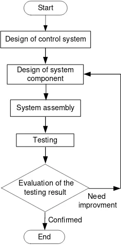
Research method is presented in Figure 1. The main parts of the active cooling system are control systems (electrical parts) and system components (mechanical parts).
2.1. Control System Design
The new active cooling system is designed to automatically work when the caliper temperature reaches 250 °C. The working condition of the vehicle
brake pad is between 200 °C to 400 °C [7]. The control system ensures that the active cooling process will work properly when the temperature of the brake pads reaches 250 °C. The diagram of the control system is shown in Figure 2.
The control system consists of a main switch, fuse, relay, buzzer, pump motor driver, temperature sensor, LCD, LED, buzzer, and micro controller. This control system is driven using programmable control system software. The temperature sensor is using the K type thermocouple, made of Chrome alloy and Alumel. This thermocouple can measure the temperature ranging between 0 °C to 1200 °C with a voltage working range between 0 to 48.8 milliVolts.
The control system hardware consists of a thermocouple installed at the brake pad, a Max 6675 thermocouple digital amplifier, and an Arduino Nano micro controller that are shown in Figure 3, Figure 4, and Figure 5, respectively.
The Arduino Nano micro controller, as shown in Figure 5, is the heart of the control system. This micro controller is programmed with the C++ programming
Figure 1. Diagram of the research method
Pump
Figure 2. Diagram of the control system
Figure 3. Thermocouple setting
Figure 4. Max 6675 thermocouple digital amplifier
LCD
language. This device is selected because of it has a small size, an open source programming and can directly connect to a computer using the USB connector.
2.2. System Component Design
The system components are the mechanical devices of the active cooling system. They consist of a water tank, pump, water pipings, and nozzle. The water tank is a reservoir or chamber to hold the water for a cooling medium. The water tank is equipped with a pump to circulate the water and an electric motor to drive the pump as shown in Figure 6. The nozzle is a device, as shown in Figure 7, designed to control the direction or characteristics of the water flow (especially to increase velocity) as the water exits an enclosed chamber or pipe.
2.3. System Assembly
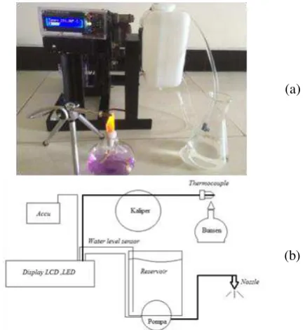
System assembly is an important stage in the research where the components of both the control system and the system components are assembled in such a way that they function as desired. The final
assembly is called the brake cooling system unit and is presented in Figure 8(a). The closed view of the control system or control unit is presented in Figure 8(b).
2.4. System Testing
The system testing is final stage of the research. The aim of system testing is to investigate the system performance for the designed conditions. The system testing is conducted in the laboratory with the system configuration shown in Figure 9.
3. Theoretical Background
The new active cooling system uses water as a cooling medium to eliminate overheating. The water as a cooling medium is stored in the tank. The water tank capacity is determined based on the energy needed for the cooling process of the disk brake. As the cooling medium, the sprayed water is changed from a liquid state at an ambient temperature into a water vapor state at 400 °C when the sprayed water contacts the hot disk brake. The total cooling energy (Qp) for the mass of the water (m) is calculated using Eq. 1.
(1) where:
CP1 : Specific heat of water
Δt1 : The increase of water temperature
U : Calorie of steam CP2 : Specific heat of vapor
Δt2 : The increase of steam temperature
m : Mass of the water
If the vehicle kinetic energy is large enough, it can be represented by the translational kinetic energy alone. The amount of the kinetic braking energy is
Figure 6. Pump and water tank configuration
Figure 7. Nozzle and cooling water spray system
Caliper
Battery Water
tank
Controller box Main
swtich Frame
Thermocouple
LED Microcontroller
Arduino Nano
LCD
(a) (b)
Figure 8. Final assembly of a new brake cooling system: (a) Brake cooling system unit, and (b) Control unit
(a)
(b)
proportional to the heat generated (Qk) and is calculated calorific value of the brake components, then the value of the water mass in Eq. 1 can be calculated by the law of energy conservation in which the value of Q = Qk. When the braking occurs within t seconds, then the required pump capacity (P) can be calculated by Eq. 3.
(2)
The water cooling system is equipped with a nozzle with a 0.1 mm hole diameter to produce a fine water spray. The smaller the nozzle hole diameter, the finer the dimension of the sprayed water droplet. The smaller the nozzle hole diameter, the larger the pump motor power required. The smaller nozzle hole diameter also caused larger loss of the sprayed water droplets due to wind blow.
4. Results and Discussion
The Caliper cooling process is automatically active when the caliper temperature reached 400 °C. To prevent the occurrence of overheating, the caliper is cooled by spraying fine water droplets into the caliper. In addition to the temperature indicator, the system is also equipped with an indicator to show the volume of the water in the storage tank.
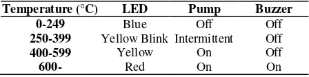
The system is equipped with 3 LED (Light Emitting Diode) light bulbs, each with a different color to be able to identify the caliper temperature. The blue bulb is on when the temperature of the caliper is still cold (under 250 °C). As the caliper temperature reaches between on and the pump continuously sprays the cooling water. The red bulb is on when the caliper temperature is more than 600 °C. This condition indicates that the brake has experienced an overheating. This condition occurs when the required braking load has exceeded the available cooling capacity. The occurrence of the brake overheating can be known when the yellow bulb is continuously on. In such conditions, a 5V buzzer attached to the system will generate a sound to alert the driver to stop the vehicle. The reference conditions designed for the control system are shown in Table 1.
The caliper temperature can also be monitored through the LCD (Liquid Crystal Display) display that shows the data of temperature being updated every half second. The 162 LCD display is selected as the monitoring device. This display can also be used to
monitor the volume of the cooling water in the reservoir or storage tank.
Table 1. The reference conditions for the control system
Temperature (°C) LED Pump Buzzer
0-249 Blue Off Off
250-399 Yellow Blink Intermittent Off
400-599 Yellow On Off
600- Red On On
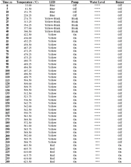
On the LCD display, the volume of water indicator with the * symbol means the water storage tank is empty and with the **** symbol means the water storage tank is full. In this testing the thermocouple is removed from the caliper. The heat increase on the caliper during braking is increased by heating the end of the thermocouple with a Bunsen burner flame. The heat is continuously added until the caliper temperature reaches all the designed temperature conditions. The results of the system responses during system testing are shown in Table 2.
The data in Table 2 show that during the system testing the caliper temperature sensor, the water level sensor as well as the measuring indicator of this system can work and perform properly. At time (t) = 20 seconds, when the caliper temperature reached 274 °C, the pump began to work intermittently and it was marked with the blinking of the LED yellow light. The continuous pump operation started at t = 45 seconds, when the caliper temperature had already reached 422 °C. At t = 205 seconds the water level indicator had not changed. This does not mean there was no reduction of the water level in the storage tank. It happened because the water volume in the storage tank still had not reached the second level of the water level sensor. The water level indicator changed at t = 210 seconds, where the caliper temperature had reached 598 °C. When the caliper began experiencing an overheating, both the red light LED and the buzzer were active (ON). The whole data gained from the system testing showed that the system worked well and in accordance with the setting conditions.
5. Conclusion
The test results show that the active cooling system using the Arduino Nano microcontroller perform well to prevent the overheating of the four-wheel disc brake vehicle. The test results also show that the system can work well for any condition.
International Journal of Innovative Research in Science, Engineering and Technology, 2(12), Dec. 2013, pp. 7741–7749.
2. Manjunath T.V. and Suresh P.M., Structural and Thermal Analysis of Rotor of Disc Brake, International Journal of Innovative Research in Science, Engineering and Technology, 2(12), Dec. 2013, pp. 7741–7749.
3. McPhee A.D. and Johnson, D.A., Experimental Heat Transfer and Flow Analysis of a Vented Brake Rotor, International Journal of Thermal Sciences,
47(4), Apr. 2008, pp. 458–467, doi: 10.1016/ j.ijthermalsci.2007.03.006.
4. Parab, V., Naik, K., and Dhale, A.D., Structural and Thermal Analysis of Brake Disc, International Journal of Engineering Development and Research, 2(2), Jun. 2014, pp. 1398–1403.
5. Abhang, S.R. and Bhaskar, D.P., Design and Analysis of Disc Brake, International Journal of Engineering Trends and Technology, 8(4), Feb. 2014, pp. 165–167.
6. Alam, S.E., Vidhyadhar, Y., Sharma, P., and Jain, A., Thermal Analysis of Disc Brake Rotor: A
Table 2. Response of the system during system testing
Time (s) Temperature (°C) LED Pump Water Level Buzzer
0 33.00 Blue Off **** Off
5 81.50 Blue Off **** Off
10 151.75 Blue Off **** Off
15 228.25 Blue Off **** Off
20 274.75 Yellow-Blink Blink **** Off
25 313.25 Yellow-Blink Blink **** Off
30 354.25 Yellow-Blink Blink **** Off
35 377.00 Yellow-Blink Blink **** Off
40 396.50 Yellow-Blink Blink **** Off
45 422.50 Yellow On **** Off
50 436.00 Yellow On **** Off
55 452.25 Yellow On **** Off
60 458.50 Yellow On **** Off
65 467.25 Yellow On **** Off
70 472.25 Yellow On **** Off
75 479.25 Yellow On **** Off
80 475.25 Yellow On **** Off
85 480.75 Yellow On **** Off
90 489.25 Yellow On **** Off
95 494.50 Yellow On **** Off
100 497.25 Yellow On **** Off
105 496.50 Yellow On **** Off
110 499.75 Yellow On **** Off
115 504.50 Yellow On **** Off
120 509.00 Yellow On **** Off
125 509.75 Yellow On **** Off
130 508.50 Yellow On **** Off
135 512.50 Yellow On **** Off
140 523.75 Yellow On **** Off
145 536.50 Yellow On **** Off
150 542.75 Yellow On **** Off
155 542.00 Yellow On **** Off
160 542.50 Yellow On **** Off
165 550.75 Yellow On **** Off
170 563.50 Yellow On **** Off
175 569.50 Yellow On **** Off
180 572.50 Yellow On **** Off
185 581.00 Yellow On **** Off
190 585.75 Yellow On **** Off
195 589.50 Yellow On **** Off
200 592.00 Yellow On **** Off
205 595.75 Yellow On **** Off
210 598.75 Yellow On *** Off
215 603.50 Red On *** On
220 605.75 Red On *** On
225 610.00 Red On *** On
230 615.75 Red On *** On
235 619.00 Red On *** On
Comparative Report, Journal of International Sciences and Computing Technologies, 3(2), Apr. 2015, pp. 196–200.
7. Radhakrishnan, C., Yokeswaran, K., Vengadesprasadh, M., Visnuhasan, A., Vimalraj, T., and Velusamy, M., Design and Analysis of Disc Brake with Titanium Alloy, International Journal of Innovative Science, Engineering & Technology, 2(5), May 2015, pp. 1044–1050.
8. Dewanto, J. and Wijaya, A., Sistem Pendingin Paksa Anti Panas Lebih (Over Heating) Pada Rem Cakram (Disk Brake) Kendaraan [Forced Cooling System for Preventing Overheating on a Vehicle Disc Brake], Jurnal Teknik Mesin [Journal of Mechanical Engineering], 12(2), Oct. 2010, pp. 97– 101, doi: 10.9744/jtm.12.2.97-101.