98
EXAMPLES OF DIGITAL EQUALIZERS FOR SINGLE CARRIER COMMUNICATION
Yunita dan Luis Sanchez
Electro Department State Polytechnic of Pontianak Email: [email protected]
Abstract: Equalization is crucial in digital communication. The transmitted signal can be severely affected by phenomena occurring in the channel, resulting in Intersymbol Interference. Equalization provides the means for correcting such negative effect. Being such a wide area of study, our interest is centered around a particular type of equalizers: adaptive equalizers. Theoretical concepts related to Adaptive Equalization are discussed in the second part in order to understand the datasheets of real commercial devices presented in part three. It is indeed the goal of this paper to present these examples of equalizers: a multi-mode QAM demodulator (TDA8046) manufactured by Philips Semiconductors and a Digital Filter (GC2011) manufactured by Graychip Inc. used in a Digital PSK and QAM demodulator.
Keywords: digital equalizers, equalization, demodulator, PSK, QAM
INTRODUCTION
Corruption and transformation of the transmitted signals in a given channel are present in digital communication systems. Intersymbol Interference (ISI), caused by multipath propagation is, among others, one of the undesirable effects caused by the channel due to its own characteristics. This specific corruption of the signal can be defined as the distortion caused by the resulting overlap of received symbols. As a result, the received signal experiments a high bit error rate. In order to handle this problem, equalization tries to compensate for those unwanted effects. Even if the characteristics of the channel cannot always
be known “a priori” (for example, a
telephone call in which the call route will be always different), equalization can
provide the means to adaptively compensate for varying conditions. [1]
Vokasi, Desember 2014, Th. X, No. 2
we provide the description of the commercial uses of Adaptive Equalization.
Adaptive Equalization Principles Intersymbol Interference
The signal at the receiver side consists of the direct signal and the reflected signals, which are caused by elements such as buildings or trees in the vicinity of transmission lines, causing multipath propagation. As a result, the signals overlap and produce a distorted signal. With the distortion and the interference between symbols considered as noise, making the communication having a high error rates. This phenomenon is known as Intersymbol Interference (ISI) which causes frequency selectivity channel. To overcome this, equalizers compensate for distortions in the received signal, hence reducing ISI. [1].
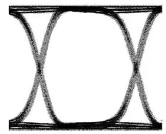
To have a better understand on ISI
phenomenon, the “eye diagram” is used. In
this type of diagram, as shown in figure 1, we can visualize the superposition of multiple bits having different delays, gains and phase, transmitted to the receiver. [7]
Figure 1. a). Eye diagram of signal with ISI
b). Eye diagram of signal without ISI [6]
Structure of Equalizers
Linear Transversal Equalizers
The transversal (tapped-delay-line) equalizer is the simplest structure in equalization. Its basic working principle consists of considering the current and past values of the received signal and weighting them by coefficients (or tap gains) cn and
performing a sum in order to produce the output. The samples of the received signal at the symbol rate are stored in digital shift registers and the equalizer output samples zk
are computed digitally once per symbol according to:
(1) Where t0 corresponds to the sample timing
and N is the number of equalizer coefficients. [1]
Examples of Digital Equalizers for Single Carrier Communication
Figure 2. Linear Equalizer [1]
Another approach is to choose the coefficients so that the mean-square error (MSE), this means, the sum of squares of all the ISI terms plus the noise power at the output of the equalizer, is minimum. LMS is considered always as Adaptive Equalization, which will be explained later in this document. In this case, it is important to note that the delay introduced by the equalizer depends on the position of the main or reference tap. Usually, this tap's gain has the biggest magnitude. [1]
Decision Feedback Equalizer
The Decision Feedback Equalizer is a type of adaptive equalizer consisting of a
The output of the feedforward and the feedback filter is subtracted in order to get the decision value of the equalizer . Afterwards, the signal is taken to the decision device which produces the symbol
. By assuming this past decision value to be correct, this value is fed back into the feedback filter as the input signal. [1]
Together with the training signal or the kth symbol decision , the output of the decision device derives the error as the parameter to get the feedback coefficients according to:
(2)
With m = 1, …, M. [1]
A diagram of a Decision Feedback Equalizer is shown in figure 3.
INPUT T T T
Figure 3. Decision feedback filter [2]
Fractionally Spaced Equalizer
The Fractionally Spaced Equalizer (FSE) is a type of linear equalizer. The difference between the linear transversal equalizer and the fractionally spaced equalizer is at the coefficients. In the FSE
equalizer the τ-spaced delay line tap is a fraction of, or smaller than, the symbol interval T. The bandwidth of the input of the FSE has to be equal to |f| < ½ τ, which can be done by carefully choosing the value
of τ. [2]
Vokasi, Desember 2014, Th. X, No. 2
β) /2T. And the sampling rate at the receiver is (3)
By using the FSE, the signal will be sampled at a rate at least equal to the
Nyquist rate with tap spacing T/ (1 + β). For example, if β = 1 then the tap is 1/2 T -spaced equalizer. If β = 0.5, then the tap is 2/3 T-spaced equalizer and so on.[2]
From the above explanation the tap spacing for FSE can be described as MT/N, where N and M are integers and N is greater than M. ½ T-spaced equalizer often used in many applications of FSE. [2] A diagram of FSE is shown in figure 4.
INPUT
x x x x
r(t)
c0 c1 c2 cN-1
t0+ KT
OUTPUT
Σ
zk
Figure 4. Fractionally Spaced Equalizer [2]
Adaptive Equalization
Since the characteristics of the channel may be time-variant, the coefficients of the equalizer can be updated adaptively after the training sequence, given that there is one. This way, the error signal is computed using the estimate that the receiver generates from the transmitted sequence. Adaptive Equalization is a means or algorithm that performs the adjustment of the coefficients of the equalizer. Normally, the error estimates are correct enough to allow the adaptive equalizer to maintain precise equalization. The larger the step size, the faster the equalizer tracking capability. In practice, the value of
the step is selected for fast convergence during the training period and then reduced for fine tuning during the steady-state operation. [1]
LMS
A particular algorithm for this matter is LMS (Least Mean-Square) which uses the steepest descent method in order to find the coefficients that minimize the error. In this iterative procedure, arbitrary initial coefficients are chosen. The gradient of the function formed by the coefficients is computed in these inital coefficients, and each tap weight is modified in the direction opposite to its corresponding gradient component. [2] Succeeding values of the coefficients are obtained according to:
(4)
Where Ck is the column vector of
equalizer coefficients, Gk is the gradient
vector and Δ is a positive number chosen small enough to ensure that the iterative process will converge. If the minimum MSE is reached for some k=k0 then Gk=0
(or at least close to 0), so that no further changes are done to the coefficients. [2]
Training Sequence
Examples of Digital Equalizers for Single Carrier Communication
Figure 5. Training Sequence [1]
Once the receiver has generated the synchronized version of the transmitted signal, a sequence of error signals can be coefficients closer to the unique optimum set of coefficients corresponding to the adaptation constant or step size. [1]
Data Sheets Of Equalizers
TDA8046 Multimode QAM demodulator Application and Features
This is a Multi-mode QAM demodulator for different modulation schemes (4, 16, 32, 64 and 256 QAM), with
a digital demodulator and square root cosine Nyquist filter with roll-off of 15% or 20%, a high performance adaptive equalizer, symbol rate of 7 Msymbol/s, digital detectors for generation of required control voltages for carrier and clock
application is to serve as a demodulator for digital cable TV and cable modem. [3] Equalizer description
The equalization function in the TDA8046 is carried out by means of two filters, a Feed Forward Equalizer and a Feedback Filter. The number of T-spaced taps (12 or 14) of the adaptive filter can be selected through the I2C bus. Moreover, the equalizer is based on a Decision Feedback Equalizer (DFE) structure with Least Mean Square (LMS) coefficient updating algorithm. This equalizer does not need any training sequence. [3] The block diagram of the equalizer is shown in figure 6.
FEED
Figure 6. TDA8046 DFE equalizer structure [3]
Vokasi, Desember 2014, Th. X, No. 2
(AGC) function. The settings of the equalizer taps can be read via the I2C-bus.
If the equalizer diverges, an automatic reset of the taps can be performed. [3]
The convergence steps of the FFE/DFE parts of the equalizer are programmable via the I2C-bus. When the
system locks, the steps are automatically modified for optimum performances. Besides reading the equalizer tap values, the main tap of the equalizer can also be programmed. After setting the main tap, the other coefficients can be set to zero. The equalizer settings can also be frozen via the I2C-bus. [3]
The following figure represents the QAM spectrum seen by the equalizer. It corresponds (in the frequency domain) to the multiplication of a full Nyquist spectrum by the impulse response of the channel. [3] Hence, the equalizer must compensate for the frequency selectivity of the channel, which is shown in figure 7.
Figure 7. QAM spectrum seen by the equalizer [3]
QAM demodulator using the GC2011, GC3011 and GC3021 chips
Application and Features
This is a BPSK, QPSK, and QAM radio signal demodulator. The application of this demodulator is for microwave links, cable TV decoders (either QAM or VSB
modulations), and satellite receivers. The symbol rates of this demodulator are up to 17.5 MSymbol/s with 70 MHz
demodulator’s clock. [4]
Equalizer description
The digital filter GC 2011 is proposed as a passband equalizer in the digital demodulator for PSK and QAM signals, using Fractionally-spaced Forward Equalizer (FSE). [4] Figure 8 shows the equalizer used for passband demodulator.
64 Tap I Path Filter
64 Tap Q Path Filter
256 Sample Snapshot RAM
GC2011 Digital Filter Chip
Clock
input output
Figure 8. Passband equalizer [4]
Before carrying out the equalization process, the signal is digitized at the nyquist rate and resampled at a rate equal to N times the symbol rate. The clock rate of this equalizer has to be equal to the clock rate of the output of the resampler. The FSE uses a 64 T/4 spaced equalizer, which has the same delay value as a 32 tap T/2 spaced equalizer. The real part of the sampled
signal is used for the equalizer’s input, and
Examples of Digital Equalizers for Single Carrier Communication
with reduced intersymbol interference that will be used at a carrier removal chip to obtain the data symbols. [4]
CONCLUSIONS
Even when information on Digital Equalization theory is widely available in many publications and books, it is not easy to find manufacturers that will make public the exact working principles of the devices making use of digital equalizers that they produce. The description that is available is
rather general and doesn’t always allow the
general public to verify the structure of the equalizer. Normally, the specific technical documentation about a given device is kept private for internal use within the company that manufactures the device. However, it is important to highlight that, even if the available description is not very detailed, it actually allows us to learn the most relevant characteristics of the equalizer.
In addition, we observed that, as a part of most QAM, BPSK and QPSK demodulators, an equalizer can be used to reduce intersymbol interference which causes frequency selectivity channel on digital communication. Datasheets of
“standalone” equalizers were not found,
only as part of a more complex application which is demodulators.
REFERENCES
[1] Shahid U. H. Qureshi, “Adaptive
Equalization”, Proceedings of the
IEEE, vol. 73. No. 9, September 1985.
[2] Proakis, John G., “Digital Communications”, 3rd ed., McGraw-Hill series in electrical and computer engineering communications and signal processing, New York, 1995.
[3] Anonym, “Integrated Circuits-Data Sheet TDA8046 Multi-mode QAM
Demodulator”, Product Specification,
Philips Electronics N.V., 19 November 1996.
[4] Gray, Joseph H., “Graychip Application Notes: Building Digital PSK and QAM Demodulator Using
The GC2011 and GC3011 Chips”,
Revision 2, 17 August 1994.
[5] Anonym, “GC2011A 3.3 Digital
Filter Datasheet”, Texas Instruments,
SLWS129A, Texas Instrument Corporated, 21 March 2000.
[6] Anonym, “MAXIM 3.2 Gbps Quad Adaptive Cable Equalizer with Cable Driver – MAX3802”, Maxim Integrated Products, 2006.
[7] Anonym, “Eye Diagram for Digital
Communications”,
![Figure 3. Decision feedback filter [2]](https://thumb-ap.123doks.com/thumbv2/123dok/1402711.2023664/3.595.309.520.201.432/figure-decision-feedback-filter.webp)
![Figure 5. Training Sequence [1]](https://thumb-ap.123doks.com/thumbv2/123dok/1402711.2023664/5.595.314.543.542.673/figure-training-sequence.webp)
![Figure 8. Passband equalizer [4]](https://thumb-ap.123doks.com/thumbv2/123dok/1402711.2023664/6.595.321.549.292.450/figure-passband-equalizer.webp)
