AN INTELLIGENT ABS CONTROL BASED ON FUZZY
LOGIC. AIRCRAFT APPLICATION
by
Ioan Ursu, Felicia Ursu
Abstract. Over the past ten years, fuzzy logic, as main component of artificial intelligence, has significantly influenced the design of controlled systems. Focusing on applied mathematics field, the paper proposes an antilock-braking system (ABS) for a Romanian military jet. It is well known that in the ABS brake, the control is considered from a “panic stop” viewpoint: the ABS is designed to stop the vehicle as safely and quickly as possible. The control target is to maintain friction coefficients between tire and road within “safe” ranges, to ensure the avoiding of wheel’s blockage and, consequently, the preservation of vehicle lateral stability and an as reduced as possible stopping distance. As matters stand as physical phenomenon, the ABS control strategy synthesis was thought using fuzzy logic. In brief, the description of this control strategy is as follows. The slip ratios of rear aircraft wheels are inferred, having from measurements (or from integration, in the case of model simulation) angular velocities of front wheels. The observing of these slip ratios, resulting from control variables applied in system, serves as basis of a phenomenological scenario – a road label inferring diagram – conceived to on line decide, via a fuzzy logic reasoning, upon the most suitable new control variables to apply at the current sample step. Control variables are synthesized in last component of a standard Mamdani type fuzzy logic control triplet: fuzzyfier, rules base and defuzzyfier. A rules base, clustered according to three road conditions – dry, wet and ice – is defined. The obtained fuzzy control variable is tuned taking into account the strong changes in the aircraft speed during the landing brake process. A sui generis searching of optimal braking is also sketched. The simulation results show that proposed ABS algorithm ensures the avoiding of wheel’s blockage, even in the worst road conditions, with additive measurement noise. Moreover, as a free model strategy, the obtained fuzzy control is advantageous from viewpoint of reducing design complexity and, also, antisaturating, antichattering and robustness properties of the controlled system. Considering previous researches of the authors, fuzzy logic is likely to be the most efficient technique in certain fields of control synthesis.
Key words: fuzzy control, Mamdani fuzzy controller, antilock-braking system (ABS), aircraft landing, mathematical modelling, numerical simulation.
1. Introduction
and reducing design complexity. Philosophically, the essential part of intelligent control research was carried out on the same premises as Han’s vision on control theory (Han, 1989), which is free of a few fundamental limitations, such as linearity, time invariance, accurate mathematical representation of plant etc.
In the present paper, a new fuzzy controller is proposed. The numerical illustration of ABS algorithm working is given using the data concerning the Romanian military jet IAR 99.
2. Airplane brake mathematical model
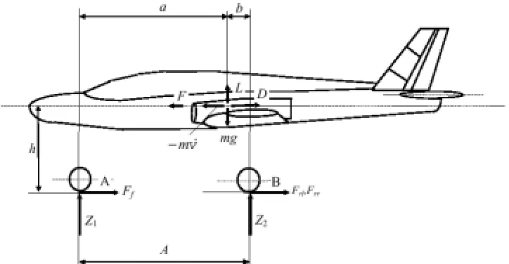
In this section the construction of a airplane brake model is performed with a view to obtain a framework of ABS fuzzy logic controller validation. The controlled system is represented by the main wheels rear wheels of the landing gear. The motion dynamics arising from the rotation of the vehicle about the vertical axis, or from uneven braking forces applied on wheels, are not considered. The straight-line braking maneuver holds on horizontal road. Thus, the lateral tire forces are neglected; the effects of pitch and roll are also neglected. Consequently, when the airplane is braking or accelerating, the tractive forces Ff , Frl, Frr, developed by the road on the tire, are
proportional to the normal forces Z1 and Z2l= Z2r= Z2 of the road acting on the tire, as
illustrated in Fig. 1: Ff = φlZ1, Frl= φlZ2, Frr= φrZ2. In the above, by Ff, Frl, Frr were
denoted the front, the left rear and the right rear tractive forces; is the road adhesion coefficient at front wheel; φl , φr are the road adhesion coefficients at rear wheels. The
coefficient φis taken constant and the coefficients φl, φlare functions of the wheel slip
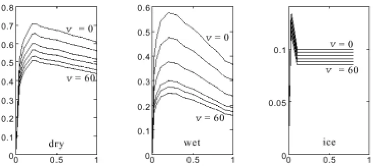
[image:2.595.126.488.416.604.2]αand depend, as parameters, on the airplane velocity v and the road conditions c: dry, wet or ice. Thus, φl:= φl(α, v, c), φr=φr (α, v, c).
Considering the Newton’s second law along the horizontal axis, the moments about the contact points A, B of the tire and the front and rear wheel dynamics, respectively, gives:
where: m – total mass of the airplane; F – thrust; D – drag; L - lift; φ – air density; CD
– drag coefficient; CL- lift coefficient; S - wing area; h - height of the airplane sprung
mass; A - distance between front wheel and rear axle; g - acceleration due to gravity; a
- distance from center of gravity to front landing gear's wheel; b - distance from center
of gravity to (rear) landing gear's axle; I - moment of inertia of the each rear wheel; R -
radius of tire; ωl, ωrangular velocities of the left and, respectively, right rear wheels;
[image:3.595.121.488.297.460.2]Mbl, Mbrleft and, respectively, right rear wheel brake torques.
Fig. 2 – Parametric dependencies of road adhesion coefficients φl(α, v, c), φr(α, v, c)
Solving for Z1 and Z2 the first three equations of the system (1), one obtains
Without braking, v = ωR and, therefore, α = 0. In severe braking, it is common to have
ω = 0 while v
≠
0, or α = 1, which is called wheel lockup.The brake proportionality constant kbrelates, via the relations
Mbl= kbPl, Mbr= kbPr (4)
the torques Mbl, Mbr on the one hand, and pressures Pl, Pr in brake cylinders, on the
other hand. The following first order linear differential equation was considered representative for the valve-brake cylinder system
where k pis a proportionality ratio Pmax / umax, P is the pressure in brake cylinder, u is
the control variable (current to servovalve), τbcis time constant of brake cylinder and k
is the step of control insertion; the pressures Pland Prare thus the following solutions
of the equations (5)
Index w marks the left or right wheel. Initial control
u
w,0=
u
*,
w
=
l
,
r
, are given on Tt ≤
≤
0 ; also, the initial pressures Pw,0 =0,w=l,r P are settled at k = 0. The constant pressures Pw,kare given by recurrence equations
because Pw,k, are defined by continuous evolution of pressures as
were assumed from table representasions (see Alexandru et al., 2000) and are shown as interpolated versions in Fig. 2. These functions represent an extended Pacejka model (Mauer, 1995) for longitudinal braking, which takes into account the decreasing of road adhesion coefficients by about 50-60% as the velocity v increases from 0 to 60 m/s.
3. Fuzzy logic control synthesis
To avoid supplementary difficulties generated by the braking of all wheels of the landing gear, consider only braking of the main wheels - the rear wheels; thus, one has at command the real velocity of the airplane, as given by the angular velocity of the front wheel. The slip ratios of rear wheels are thus obtained, having from measurements angular velocities of these wheels. The road label “l” can be inferred by observing the slip ratio resulting from a given control variable: this is the basis of a phenomenological scenario conceived to on line decide via a fuzzy logic reasoning upon the most timely new control variables to apply at the current sample step. This scenario is shown in Fig. 3. At each decision step k, when t = kT, for each braked wheel the three input variables of the road label “l” inferring diagram are: 1) wheel slip α; 2) predicted wheel slip
α
; 3) previous value of control variable, u(k−1). To partially compensate for the delay effect of the time constantτ
bc(six sampling periodsτ
, in our problem), a predicted slip ratioα
is computed from a linear regression of the last three sampled values of the slip (see Fig. 4) and is extrapolated to the next period of lengthτ
bc/
2
considering at step k the control as unapplied: thus, the algorithm causes the fuzzy logic controller to issue a new control variable at each three sample periods, i.e., at each T = 0.015 s (see Fig. 4).The following nine threshold-values concerning input variables in the road label “l” inferring diagram mean: αb- blockage threshold slip at the braking start point;
α
bd-blockage threshold slip in the case “l” = “dry”;
α
bw - blockage threshold slip in the case “l” = “wet”;α
bi - blockage threshold slip in the case “l” = “ice”;α
i - predicted“wet” road label setting in logical conjunction with threshold slip
α
w;α
dthreshold slip for “dry” road label setting in logical conjunction with threshold control ud*; u*d - threshold-control for “dry” road label setting in logical conjunction with threshold-slipd
α
.These threshold values and the value u*of the control variable delivered to the system at the braking start point can be fine tuned by a trial and error type process, but with no guarantee of finding optimal results. To automate this process, one can use genetic algorithms. This alternative concerns both the cases of numerical simulation and on line airplane brake testing, but was not considered in the paper.
Generally, a fuzzy logic controller consists of three main components: a fuzzyfier, a fuzzy reasoning or inference engine, and a defuzzyfier (Ghazi Zadeh et al., 1997) . The fuzzyfier component convert the crisp input signals into their relevant fuzzy variables using a set of linguistic terms. Let us remember the crisp input signals at decision step k: wheel slip α, predicted wheel slip
α
and previous value of control variableu
k−1 . The following fuzzy variables will be considered: Z (zero), Zs (zero small), s (small), m (medium), L (large), VL (very large). Thus, fuzzy sets and their pertinent membership functions are produced, see Fig. 5; for the sake of simplicity, triangular membership functions were chosen for α andα
and a singleton type membership function for u. Scaled input variables and scaled fuzzy control ensure an unified, independent of various applications, calculus. The fuzzy reasoning characterizes ABS controller as a Mamdani fuzzy controller: a set of expert-type IF... THEN... rules, generally derived from a human operator experience or intuition, will be finally exploited in control rule deriving, by Mamdani’s method of minimum. This rules base is clustered having in view the road label “l” and represents a some processing of the rules base given by Mauer (1995): “l ” = “dry”: 1) IFα
≠
VL
THEN u = L; 2) IF α = L and u = L THEN u = m; 3) IF α = s and u = L andα
≠
VL
THEN u = L; 4) IF α = m andα
≠
VL
THEN u = L; “l ”= “ice”: 1) IF α = Zs and u =The fuzzyfier concerns the transforming of fuzzy IF... THEN... rules into a mathematical formula giving the output control variable u. To be more specific, if the pair (
α
,α
) is measured (or calculated) at the time step k as (scaled)( )
α
k0,α
0k , thecontrol u follows as a consequence of Mamdani fuzzy machinery inference. Having in mind the fuzzyfier stage (Fig. 5) and rules base described, a number of I (dependent on “l” and time step k ) IF... THEN... rules will operate. A such rule may be, for instance, the following rule derived from the validated rule 4 “dry” :
As matters stand, the rule (9) defines a fuzzy set
A
1i×
A
2i×
B
i≡
m
×
L
×
L
in the input-output Cartesian product spaceR
+3 , whose membership function can be defined in the manner(other variants, e.g. product instead of min, can be chosen). For simplicity, the singleton-type membership function
µ
B(
u
)
of control variable has been preferred here. In this case, i( k)B u
2) the center-average type defuzzyfier; and 3) the min inference, these I IF... THEN... rules can be transformed, at each time step kT , into the following formula giving the crisp control u (Wang and Kong, 1994)
This value will be rounded off to the nearest singleton abscissa (see Fig. 5b). 4. Fuzzy control value moderating and a sui generis optimal braking search
Due to the lift force, the tractive forces Ff,Frl,Frr developed by the tire strongly change with vehicle speed. To counteract this effect on braking process, the obtained fuzzy control u given in (11) is tuned, taking into account just the vehicle speed
The correction value
u
c is thought as a strictly monotone increasing functionand parameters
β
1,
β
2, will be derived from the equationswhere
v
0 and vfare, respectively, the initial and final values considered in the braking process.Thus
Another observation can improve the ABS fuzzy logic algorithm. By inspecting the given also in (1) equations
one infers that a value indicator of the current road adhesion coefficient
ϕ
wis at hand: the left-hand side of equation (17). To have this opportunity, the mathematical model must be simplified by introducing the hypothesisϕ
l=
ϕ
r:=ϕ
wconcerning the road adhesion coefficients at rear wheels. Indeed, in this condition the right-hand side of the equation (17) is increasing withϕ
w and, by measuring the variables.
k
ω
andP
w, one obtains a sign on the variation ofϕ
w. Preserving a mathematical model with distinct left and right road adhesion coefficients, the clamed opportunity doesn't holds, because in this situation the right-hand side of the equation (17) should be increasing with respect to, sayϕ
r, and decreasing with respect to the other coefficientϕ
l. Thus, in the case of simplified mathematical model, an heuristic procedure of optimal braking searching can be conceived. Namely, the control (13) will be applied at system input so long as the latest three indirectly measured values ofϕ
w, at sampling times iτ
, do not fulfill the inequalitiesIf the above inequalities hold, the control uw,k =0 is decided to system input, until the inequality
holds, when the control (13) is again applied at system input, and so on. 5. Numerical simulations and concluding remarks
Numerical simulation of the mathematical model (2) is enabling engineer to evaluate thoroughly: 1) the ABS fuzzy logic control working; 2) a first guess of algorithm’s threshold
α
b,
α
bd,
α
bw,
α
bi,
α
i,
α
w,
u
w*,
α
d,
u
*d. The system parameters, concerning the Romanian military jet IAR 99, were as follows: m = 3850 kg, A = 4.235 m, a = 3.772 m, h = 1.092 m, R = 0.263 m, I = 0.615 kgm2 , F = 95 X 9.8 N,s
N
v
L
u
P
k
p/
,
0
.
02
,
1
.
25
18
.
71
0
.
618
2/
2
,
bc0
.
03
max
max
=
=
×
×
×
=
N v
D=1.25×18.71×0.1088× 2/2 (with v given in m/s),
1
/
k
b=
0
.
4135
×
0
.
98
daN/cm2/daNm,v
0=
50
m/s,v
0=
10
m/s, Pmax = 1250 N/m2 , umax = 10 mA. Statevariables v, ωl, ωr, with initial conditions v(0) = ωl(0)R = ωr(0)R = 50 m/s, are
obtained by integrating of the system (2).
Many numerical explorations were performed. As representative for simulation, Fig. 6 shows the fuzzy controller’s response to following inserted in system road conditions (for each wheel, the first four sequences, each of 3 s length, are followed by a fifth, variable as time, sequence). The succession of the road conditions sequences are: dry,
very soft surfaces, such as gravel or unpacked snow, it is accepted that ABS may actually lengthen stopping distances.
Figures 8 and 9 show samples of tuning fuzzy control moderating parameters on dry road: the values θ = 1/0.5 and φ = 1/1.5 seem to be the most suitable from stopping time viewpoint.
Note again that the failing of real road conditions guess, in fact the failing of occurring adhesion coefficients guess, means no algorithm failing; due to the rigor of road label “blockage” specification uw,k = 0, the occurrence of a real wheel blockage,
when the brake is supervised by the proposed algorithm, is entirely improbable. To make more efficacious the decision uw,k = 0, a switching valve is designed: when the
control value uw,k = 0 is settled, the valve switches on the time constant τbc/10,
complexity and provides antisaturating and antichattering properties to the controlled system, thus favourising its robustness (see, also, I. Ursu and F. Ursu, 2002).
Such a control synthesis in the case of airplane landing is not available in a current literature of the field, to the best of author’s knowledge.
References
[1].Alexandru, D., F. Popescu, V. Andrei (2000). Requirements concerning an IAR 99 optimized braking system. INCAS (“Elie Carafoli” National Institute of Aerospace Research) Internal Report 2503.
[2].Ghazi Zadeh, A., A. Fahim, M. El-Gindy (1997). Neural network and fuzzy logic applications to vehicle systems: literature survey. International Journal of Vehicle Design, 18, 2, 132-193.
[3].Han, J. (1989). Control theory: it is a theory of model or control? Systems Science and Mathematical Sciences, 9, 4, 328–335.
[4].Mauer, G. F. (1995). A fuzzy logic control for an ABS braking system. IEEE Transaction on Fuzzy Systems, 3, 4, 381-388.
[5].Passino, K. M., S. Yurkovich (1998). Fuzzy control. Addison Wesley Longman, Menlo Park, CA (later published by Prentice Hall).
[6].Ursu, I., F. Ursu, T. Sireteanu, C. W. Stammers (2000). Artificial intelligence based synthesis of semiactive suspension systems. The Shock and Vibration Digest, Sage Publications, 32, 1, 3–10.
[7].Ursu, I., F. Ursu, L. Iorga (2001). Neuro-fuzzy synthesis of flight control electrohydraulic servo. Aircraft Engineering and Aerospace Technology, MCB University Press, 73, 5, 465–471.
[8].Ursu, I., F. Ursu (2002). Active and semiactive control (in Romanian), Romanian Academy Publishing House, Bucharest.
[9].Wang, L.-X., H. Kong (1994). Combining mathematical model and heuristics into controllers: an adaptive fuzzy control approach. Proceedings of the 33 rd IEEE
Conference on Decision and Control, Buena Vista, Florida, USA, 4, 1994,
4122–4127.
[10].Wang, L. (1994). Adaptive fuzzy systems and control design and stability analysis. Englewood Cliffs, New Jersey, Prentice Hall.
[11].Yen, J., R. Langari, L. A. Zadeh Eds. (1995). Industrial applications of fuzzy control and intelligent systems. New York, IEEE Press.