DOA: DSR over AODV Routing
for Mobile Ad Hoc Networks
Rendong Bai and Mukesh Singhal,
Fellow,
IEEE
Abstract—We present a lightweight hierarchical routing model, Way Point Routing (WPR), in which a number of intermediate nodes on a route are selected as waypoints and the route is divided into segments by the waypoints. Waypoints, including the source and the destination, run a high-level intersegment routing protocol, while the nodes on each segment run a low-level intrasegment routing protocol. One distinct advantage of our model is that when a node on the route moves out or fails, instead of discarding the whole original route and discovering a new route from the source to the destination, only the two waypoint nodes of the broken segment have to find a new segment. In addition, our model is lightweight because it maintains a hierarchy only for nodes on active routes. On the other hand, existing hierarchical routing protocols such as CGSR and ZRP maintain hierarchies for the entire network. We present an instantiation of WPR, where we use DSR as the intersegment routing protocol and AODV as the intrasegment routing protocol. This instantiation is termed DSR over AODV (DOA) routing protocol. Thus, DSR and AODV—two well-known on-demand routing protocols for MANETs—are combined into one hierarchical routing protocol and become two special cases of our protocol. Furthermore, we present two novel techniques for DOA: one is an efficient loop detection method and the other is a multitarget route discovery. Simulation results show that DOA scales well for large networks with more than 1,000 nodes, incurring about 60 percent-80 percent less overhead than AODV, while other metrics are better than or comparable to AODV and DSR.
Index Terms—Ad hoc networks, routing protocols, scalability, hierarchical, DSR, AODV, MANET.
Ç
1
I
NTRODUCTIONW
IRELESS networks are rapidly becoming a common-place: Wi-Fi cards are built in computing devices as a standard configuration; hotspots are installed in more and more places, such as campuses, offices, and hotels. Soon, numerous mobile and embedded devices will join the revolution of pervasive computing. Existing infrastructure-based networks may become infeasible to support all of these new participants because the number of wireless devices is increasing exponentially. This leads us to envision future large networks where hosts communicate with each other in an ad hoc manner. Such networks are generally termed as mobile ad hoc networks (MANETs). The following is an example of future MANETs. In an area such as a campus or a city, portable devices (laptops, PDAs, smart phones, etc.) communicate with each other according to a set of ad hoc networking standards and a certain number of access points may be installed to form mesh networks. In such an environment, it will become a reality for an individual to talk to anyone digitally from anywhere (within the area) at no or little cost. There are a number of ongoing projects that aim to study and prototype large-scale ad hoc networks, for example, the ExScal project in OSU [1], the Terminodes project in Switzerland [2], and the Roofnet project at MIT [3].Routing has always been one of the key challenges in MANETs and the challenge becomes more difficult when the network size increases. Many routing protocols for MANETs have been proposed (see [4] for a review) and these protocols can be classified into different categories according to different criteria. If classified by the manner in which they react to network topology changes, routing protocols can be grouped into proactive (or table-driven) protocols and reactive (or on-demand) protocols (though several hybrid protocols exist). If classified by the role of routing nodes and the organization of the network, routing protocols can be grouped into flat protocols and hierarch-ical protocols.
Proactive protocols propagate topology information periodically and find routes continuously, while reactive protocols find routes on demand. Performance analysis and simulation results [5] show that, generally, reactive protocols outperform proactive protocols in terms of packet delivery ratio, routing overhead, and energy efficiency. Therefore, research interests have been mainly focused on reactive protocols. Dynamic Source Routing protocol (DSR) [6] and Ad hoc On-demand Distance Vector routing protocol (AODV) [7] are two well-known reactive routing protocols.
DSR and AODV both belong to the category of flat routing protocols, in which all nodes are assigned the same functionalities. Flat routing protocols work well for small networks containing a few hundred nodes; however, their performance degrades rapidly as the network grows because of the routing overhead. Hierarchical routing protocols are developed to solve the scalability problem. In these protocols, the network is divided into groups and a subset of nodes are assigned special functionalities, typi-cally, coordinating roles. Clusterhead-Gateway Switch
. The authors are with the Wireless and Distributed Systems Research
Group, Department of Computer Science, University of Kentucky, James F. Hardymon Building, Room 207, 301 Rose Street, Lexington, KY 40506. E-mail: {rdbai, singhal}@cs.uky.edu.
Manuscript received 1 Feb. 2005; revised 5 Aug. 2005; accepted 17 Oct. 2005; published online 16 Aug. 2006.
For information on obtaining reprints of this article, please send e-mail to: [email protected], and reference IEEECS Log Number TMC-0022-0205.
Routing (CGSR) [8] is a typical hierarchical routing protocol. CGSR divides the network into clusters that are circular regions with the radius of a predefined hop count. After the network is divided into clusters, local route maintenance activities will only affect a few neighboring clusters, while other clusters remain untouched. Therefore, scalability is achieved. However, the overhead to dynami-cally maintain the hierarchy may be high in mobile environments.
As a network grows, routes between sources and destinations become longer. When a route breaks due to node mobility or node failure, flat routing protocols like DSR and AODV typically discard the whole original route and initiate another round of route discovery to establish a new route from the source to the destination. When a route breaks, usually only a few hops are broken, but other hops are still intact. Thus, this approach wastes the knowledge of the original route and may cause significant overhead in global route discoveries. An optimization to AODV is local repair, as described in [9]. However, the local repair is suitable for situations where link failures occur near the destination.1This is because in AODV, intermediate nodes only know the destination and the next hop for a route and the target of the local repair has to be the destination. If a link failure occurs far from the destination, it would be better for the source to discover a new route directly. Therefore, the main motivation of our work is as follows: By establishing and maintaining active routes hierarchically, a broken route can be repaired locally wherever the link failure occurs along the route and fewer global route discoveries need to be initiated by the source node. Consequently, the new routing protocol incurs less routing overhead and exhibits better scalability and performance.
In this paper, we present a scalable routing model for MANETs, Way Point Routing (WPR), which maintains a hierarchy only for active routes. In WPR, a number of intermediate nodes on a route are selected as waypoints and the route is divided into segments by the waypoints. The source and the destination are also considered as waypoints. One distinct advantage of our model is that when a node on the route moves out or fails, instead of discarding the whole original route and discovering a new route from the source to the destination, only the two waypoints of the broken segment have to find a new segment. This will have a clear performance advantage,
such as low routing overhead and low end-to-end delay. Waypoints run a high-level intersegment routing protocol, while nodes on each segment run a low-level intrasegment routing protocol.
Compared to hierarchical routing protocols such as CGSR [8] and Zone Routing Protocol (ZRP) [10], WPR is a lightweight scheme for two reasons. First, the hierarchy in WPR only involves nodes on active routes, while the hierarchy in CGSR and ZRP involves all nodes in the network. Second, the hierarchy in WPR is easier to maintain. The hierarchy in CGSR and ZRP is more complicated because it is built in two dimensions, i.e., the network is divided into regions as shown in Fig. 1, while the hierarchy in WPR is built in one dimension, i.e., a route is linearly divided into segments as shown in Fig. 2. More-over, nodes in WPR work uniformly because the assign-ment of waypoint nodes and nonwaypoint nodes is specifically for each route. A node may act as a waypoint node for one route and may act as a nonwaypoint node for another route. This facilitates the uniform consumption of resources at nodes in MANETs. In hierarchical routing protocols such as CGSR, nodes work nonuniformly and a center node may become a traffic bottleneck and drain its battery early.
As an instantiation of WPR, we choose DSR and AODV as the intersegment and the intrasegment protocols, respectively. We term this instantiation as DSR over AODV (DOA) routing protocol. Thus, DSR and AODV—two well-known routing protocols for MANETs—are combined hierarchically. Moreover, they become two special cases of our scheme: When the segment length is set to 1, DOA works in DSR mode because each hop is a segment and the intersegment routing protocol (DSR) dominates; when the segment length is set to a large number, DOA works in AODV mode because the whole route is one segment and the intrasegment routing protocol (AODV) dominates. In this paper, we also present two novel techniques for DOA; one is an efficient loop detection method and the other is a multitarget route discovery.
The remainder of the paper is organized as follows: In the next section, we present the Way Point Routing model. In Section 3, we describe the DOA routing protocol. Section 4 presents the simulation setup and results. Related work is presented in Section 5. We draw conclusions in Section 6.
2
T
HEW
AYP
OINTR
OUTING(WPR) H
IERARCHYOur intuition for the Way Point Routing hierarchy comes from a close comparison of DSR and AODV routing protocols and from an attempt to make DSR protocol scale
1. In Section 6.12 (Local Repair) of AODV draft [9], “When a link break in an active route occurs, the node upstream of that break MAY choose to repair the link locally if the destination was no farther than MAX_REPAIR_TTL hops away.”
Fig. 1. A hierarchy in two dimensions.
to larger networks. Thus, we first present the comparison and then introduce the WPR routing scheme.
2.1 Comparison of AODV and DSR
Although both DSR and AODV belong to reactive routing protocols, they work differently in a number of aspects. A good performance comparison of DSR and AODV can be found in [11]. Below are the major differences between DSR and AODV:
1. The most noticeable distinction between DSR and AODV is that the packet header overhead in DSR is larger than AODV because data and control packets in DSR typically carry complete route information. The header overhead restricts the scalability of DSR. 2. In terms of route learning capability, DSR can learn more routing information from the traffic than AODV, because DSR packets contain complete route information. This generally results in DSR generat-ing fewer route discoveries.
3. DSR is potentially able to obtain multiple routes through multiple route replies. In DSR, the destina-tion replies to all valid received route requests (RREQs) but, in AODV, the destination replies only to the first valid received RREQ. Pearlman et al. [12] showed that in multiple channel net-works, multiple path routing can significantly improve the performance.
4. Compared to DSR, AODV is able to run on larger networks. As observed in our simulations (Section 4), DSR delivers 51 percent of data packets for networks with 600 nodes in an area of2;8002;800 m2, while AODV delivers 89 percent of data packets for the same configuration. Route information in AODV is maintained in a distributed manner—every inter-mediate node along the route keeps a forwarding pointer (next hop) toward the destination; while route information in DSR is maintained by the source. A distributed manner is more suitable for MANETs.
5. If security is a major concern, DSR is easier to secure than AODV. In DSR, the source designates the path that will be used to route data packets. Therefore, DSR can select a secure route based on the trust of nodes. Lot of work on security in MANETs is based on DSR [13], [14], [15], [16]. Gupte and Singhal [17] and Hu and Perrig [18] presented surveys on security issues in MANETs.
In DSR, source routes carried in data packets are likely to cause significant overhead in larger networks where routes are longer. An Internet draft of DSR [19] states that DSR is suitable for MANETs “with up to around 200 nodes.” In both DSR and AODV, when a route breaks due to node mobility or node failure, the broken route is discarded and a new route is discovered from the source to the destination. This will have scalability and performance problems in larger networks. The local repair optimization to AODV is suitable for situations where link failures occur near the destination, as discussed in Section 1.
The problems mentioned above are inherent in flat routing protocols. In flat routing protocols, a route is
maintained at the grain of the whole path, i.e., from the source to the destination. This approach works well for small networks where routes are typically short. When the network grows, routes become longer and break more often. If routes are still maintained at the grain of the whole path, the routing overhead will be high because new routes are discovered and discarded frequently.
2.2 The Way Point Routing Approach
We define a term called manageable grain to describe the maintenance of a route. The manageable grain is coarse if a route is maintained at the grain of the whole path from the source to the destination. Flat routing protocols such as AODV and DSR maintain routes at the coarse manageable grain. A path will be discarded if one hop on the path is broken. Generally, local repair is not applicable because no finer manageable grain is available.
A finer manageable grain is required when maintain-ing routes in larger networks. In our approach, the finer manageable grain is achieved by using a hierarchy of nodes on the routes. In the hierarchy, a route is divided into several subroutes, which are termed as segments. After dividing the route into segments, we obtain a two-level hierarchical routing model: the global intersegment routing and the local intrasegment routing. At a higher level, a global intersegment routing protocol is used from the source to the destination; at a lower level, a local intrasegment routing protocol is used within each seg-ment. If needed, a hierarchy with more than two levels can be established by further dividing the segments. We use the two-level hierarchy in our discussion. In our hierarchical routing model, the manageable grain is a segment. The segment manageable grain makes it possible for the route maintenance activities to be conducted locally, typically on a segment.
We divide a route into segments by selecting a number of
waypoint nodes from the route. Therefore, we call our hierarchical routing model Way Point Routing (WPR). The source and the destination are also waypoint nodes. Other nodes on the route are termed forwarding nodes. Each segment starts with a waypoint node calledstart nodeand ends with a waypoint node called end node. The start and end nodes of a segment are generally connected by a number of forwarding nodes. Two neighboring segments share a common waypoint node, which acts as the end node of the upstream segment and the start node of the downstream segment.
longer segments can be used to reduce the overhead of maintaining the hierarchy; if nodes move faster, shorter segments can be used to facilitate route repairs. Finally, in WPR the hierarchy only involves nodes on active routes, while other nodes save their resources.
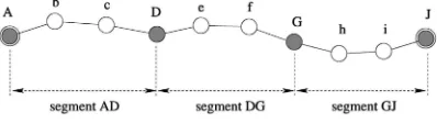
Fig. 2 gives an example of how a route from nodeAto nodeJ is divided into segments. We select nodesDandG as waypoint nodes. Source A and destination J are also waypoint nodes. Waypoint nodesDandGdivide the route into three segments: AbcD, DefG, and GhiJ.2The nodes between the start and end nodes of a segment are forwarding nodes. A segment can be simply identified by its start and end nodes. For example, segmentAbcDcan be referred to as segmentAD.
2.3 Combining AODV and DSR in WPR
For the issue of what protocols are suitable for intersegment routing and intrasegment routing in WPR, theoretically many existing protocols can be used. In our instantiation, DSR is used for global intersegment routing and AODV is used for local intrasegment routing and this instantiation is termed DSR over AODV (DOA) routing protocol. Our choice of these protocols is motivated by the following reasons:
1. DSR and AODV are two well-known on-demand routing protocols. By combining them hierarchically, we expect DOA to inherit the strengths of both DSR and AODV and, thus, exhibit better scalability and performance. Our simulation study shows that this combination indeed improves the scalability of DSR greatly and reduces the overhead of AODV significantly.
2. DOA makes it possible for DSR routing and AODV routing to coexist in the same network. In fact, DSR and AODV are two special cases of DOA. When the segment length is set to 1, DOA becomes DSR; when the segment length is set to a large number, DOA becomes AODV.
3. For local intrasegment routing, AODV is used because of its efficient operation and its ability to run on larger networks (though with a rapidly increasing routing overhead). Using AODV as the intrasegment routing protocol allows longer seg-ments to exist in WPR. This makes the segment division in WPR more flexible. If needed, long segments can be used to reduce the number of waypoint nodes on a route.
We now explain the operation of the DOA routing protocol in the next section.
3
T
HEDOA R
OUTINGP
ROTOCOLIn DOA, DSR runs at the intersegment level and only waypoint nodes are listed in headers of data packets as the source route option; AODV runs at the intrasegment level. By combining DSR and AODV hierarchically, we make DSR
work for larger networks and limit the overhead of AODV to a local range (within a segment). DOA works on an on-demand basis. In DSR, the use of promiscuous receive mode is optional, and some optimizations can take advantage of its availability. However, the use of promiscuous mode increases CPU processing overhead and power consump-tion. Thus, we choose not to use promiscuous mode. Like other on-demand routing protocols, we address four issues in DOA: route discovery, data forwarding, route main-tenance, and loop handling. Additionally, we address the issue of supporting metrics other than hop count in Section 3.5. Four types of control messages are defined: route request (RREQ), route reply (RREP), route error (RERR), and route activate (RACT). RACT message is used to set up a reverse path from the end node to the start node of a segment, and it will be explained at the end of Section 3.1.2 in detail. To distinguish messages used for intersegment routing and intrasegment routing, we add subscriptinteror
intrato messages (e.g.,RREQinterandRREQintra).
3.1 Route Discovery
3.1.1 Intersegment Route Request
When a source node requires a new route to a destination node, it broadcasts anRREQintermessage. ARREQintercan
be uniquely identified by the combination of the source address and the source’s broadcast ID number. Similarly to DSR routing protocol, the RREQinter message records the list of nodes it has traversed. When an intermediate node receives the RREQinter, it first determines whether this
request is a duplicate by looking up its request seen table. Duplicate requests are discarded. If the RREQinter is new
and its TTL is greater than zero, the intermediate node appends its address to the path recorded in theRREQinter
and rebroadcasts the request to its neighbors. Route reply by intermediate nodes3is not enabled in DOA because the
routes provided by intermediate nodes may be outdated. When the RREQinter message reaches the destination, the
destination node replies to the request as described next.
3.1.2 Intersegment Route Reply
In DSR, for one route discovery identified by a source address and a broadcast id, there is no limit on the number of RREPs that the destination can send to the source; the destination will send a RREP whenever it receives a RREQ. We observe in our simulations that most of the paths discovered by RREQ messages share a large number of common nodes; only the last few hops are different. Based on this observation, for one intersegment route discovery, we limit the number of replies that the destination can send to the source by the parameter MAX_REPLY_TIMES (which is set to 2 in our simulations).
If the length of the path recorded inRREQinterexceeds a
threshold value (DEFAULT_SEGMENT_LEN), the destina-tion divides the path into segments by selecting waypoint nodes from the path. It is worth noting that there are several ways to select waypoint nodes. A naive method is selecting waypoint nodes that divide the path into segments evenly,
2. To distinguish waypoint nodes from forwarding nodes, we use uppercase letters to label waypoint nodes and lowercase letters to label forwarding nodes.
i.e., the length (hop count) of each segment is roughly equal to DEFAULT_SEGMENT_LEN. For example, suppose the path from a sourceAto a destinationJ is
ABCDEFGHIJ;
and suppose the value of DEFAULT_SEGMENT_LEN is 3. A possible path division would be
AbcDefGhiJ;
which contains three segments: AD, DG, and GJ. The length of each segment is equal to 3. Waypoint nodes can also be selected according to other criteria, for example, speed or security association. Using lower-speed nodes as waypoint nodes apparently makes routes last longer; using nodes from the same security association makes routes more secure. We use the naive method to divide a path. The parameter DEFAULT_SEGMENT_LEN determines how many segments a route is divided into.
The destination generates aRREPinter message after the
path has been divided. The path that includes both waypoint nodes and forwarding nodes is placed into the RREPinter.
Using our example, bcDefGhiJ is placed into theRREPinter. The source address is not listed
because it appears as the destination of the RREPinter
message. This detailed path is used by intermediate nodes to establish the route and relay the RREPinter back to the
source.
We need to add more information into the RREPinter
for intrasegment routing. Similarly to AODV protocol, the sequence number of and the hop count to the end node of the current segment are carried by the RREPinter. These
two fields are denoted end_seq and end_hopcount, respec-tively. They have the same functionalities as in AODV— loop prevention and route comparison. In our example, since the current segment is the last segment and the end node is the destination, the destination sets theend seq to its own sequence number and sets the end_hopcount to 1. TheRREPinteris unicast to the source along the reverse
path contained in theRREPintermessage. Before explaining
how intermediate nodes and the source node handle the
RREPinter, we need to introduce two tables maintained by
all nodes in the network:route cacheandrouting table. Route cache is used for intersegment DSR routing, while routing table is used for intrasegment AODV routing.
An entry in the route cache uses hdestination:
source routei structure as in the DSR protocol. The route cache stores source routes from the current node to destination nodes. A source route only contains waypoint nodes. Therefore, any two neighboring nodes on a source route in DOA are one segment away from each other, instead of one hop away as in DSR. Typically, one segment contains multiple hops.
An entry in the routing table useshend node:next hopi structure similarly to the AODV protocol. An end node corresponds to a destination in AODV. The outing table stores the next hop to the end node of a segment, where the current node is either a forwarding node or the start node of this segment. The difference between the AODV routing table and the DOA routing table is that the destination field in the AODV routing table is the final destination of data
packets, while in DOA, it is the end node of a segment and is not necessarily the final destination.
When an intermediate node receives the RREPinter, it
first determines if it is a waypoint node or a forwarding node on the replied route. If it is a waypoint node, it updates both its route cache and its routing table. If it is a forwarding node, it updates only its routing table.
To update its route cache, the node inserts source routes to the destination and to downstream intermediate way-point nodes into its route cache. In our previous example, the route is AbcDefGhiJ. Upon receiving the RREPinter, node G adds hJ:Ji to its route
cache, nodeDaddshG:GiandhJ:GJito its route cache, and so on.
To update its routing table, the node inserts or updates an entry in its routing table if the intrasegment route (hend node:next hopi) in theRREPinteris new or better. For
the inserted or updated entry, the end node is the end node of the current segment and the next hop is the last node that relayed theRREPinterto the current node. Each entry in the
routing table has a Boolean type field namedstart node. It is set to true if the current node is the start node of the current segment; otherwise, it is set to false. The start node field determines whether to forward an intrasegment route error further, which will be explained in detail in Section 3.3.1.
Using the previous example, where the replied route is AbcDefGhiJ, when node h re-ceives the RREPinter, it searches for the route to end
nodeJin its routing table. If no route is found or the found route is old, a new route toJ will be inserted or updated. For the new route, the next hop isi, and the hop count is 2. When theRREPinterarrives at an intermediate waypoint
node, it means that the RREPinter is leaving a segment
where the current node is the start node and that the
RREPinter is entering an upstream segment where the
current node is the end node. Therefore, this node sets the end seq in theRREPinter to its own sequence number and
resets theend_hopcountin theRREPinterto 1.
As with AODV, at the intrasegment level of DOA, a reverse path from the end node to the start node of a segment is needed. In order to let the end node and forwarding nodes on the segment know the sequence number of and the hop count to the start node, the start node sends aroute activate (RACT) message to the end node. The RACT contains the two values, denoted start seqandstart hopcount, respectively. start seqis set to the sequence number of the start node. The initial value ofstart hopcountis 1 and it will be increased by forwarding nodes when the RACT is relayed. The RACT message is required because whenRREQinterswere propa-gated, although downstream nodes could learn upstream nodes list carried by RREQinters, the route division into
segments had not been done yet.
When the RREPinter reaches the source node that
initiated the intersegment route discovery, the source updates both its route cache and its routing table as described above. Now, the source is ready to transmit data packets as described next.
3.2 Data Forwarding
routing. The source gets a source route to the destination from its route cache and inserts the source route into the header of the data packet, as in the DSR protocol. The difference is that in DOA, a source route only contains waypoint nodes. Therefore, compared to DSR, our ap-proach reduces the header overhead of data packets and improves the scalability of source routing.
After setting the source route option for the data packet, the source node processes intrasegment routing for the first segment on the route. It gets the next hop to the end node of the first segment by looking up its routing table, like the AODV protocol. The difference is that AODV gets the next hop to the final destination, while DOA gets the next hop to the end node of the current segment. Next, the source node sends the packet to the next hop, which, typically, is a forwarding node.
The source route option of a data packet contains a field named current_seg, which is the index of the current segment on the source route. This index lets intermediate nodes on the route know which segment the data packet is being routed in. The value of current_segis maintained by waypoint nodes. When the data packet leaves an upstream segment and enters a downstream segment at a waypoint node, the value of current_seg is increased by 1. This operation belongs to intersegment routing. For intraseg-ment routing, intermediate nodes get the next hop to the end node of the current segment from their routing tables and send the data packet to that next hop. Intersegment routing (occurs only at waypoint nodes) and intrasegment routing (occurs at both waypoint and forwarding nodes) continue until the data packet reaches the destination.
3.3 Route Maintenance
Due to the dynamic nature of MANETs, links on a route may fail. Route maintenance is the mechanism to handle route breaks. A node can confirm if a packet is correctly received by the downstream node through any of the three types of acknowledgments: link-level, passive (listening to the forwarding by next hop node), and network-layer.
In flat reactive routing protocols, when a link failure occurs, typically a route error message is sent to the source and the old route is torn down. The source then starts another route discovery. Route maintenance in this manner creates a lot of route request overhead. On the other hand, a route in DOA is composed of segments. Thus, a broken route can be repaired locally, at the level of the broken segment or at the level of a few segments near the broken segment.
Two levels of route repairs are defined in DOA: intrasegment route repair and intersegment route repair. When a segment is broken, intrasegment route repair is tried first and it works in the range of one segment. If intrasegment route repair succeeds, waypoint nodes on the source route are not changed; thus, the source node does not need to be notified. If intrasegment route repair fails, intersegment route repair will be tried next and it works over multiple segments, including the broken segment and downstream segments. If intersegment route repair suc-ceeds, the repaired source route is sent to the source and the source will use the repaired route to transmit data packets thereafter. Otherwise, an intersegment route error message
is sent to the source, which subsequently may start another round of global route discovery as described in Section 3.1.1. The start node of the broken segment is the initiator of intrasegment and intersegment repairs. In the following description, we simply denote the route repair initiator as theinitiatorand denote the node that the initiator looks for (e.g., the end node of the broken segment) as thetarget.
3.3.1 Intrasegment Route Repair
Intrasegment route repair works in AODV mode. When a node finds the next hop node is unreachable, it sends a RERRintra message to its precursor nodes, which use the
current node as the next hop for some segments. Multiple segments will be broken if they all use the broken link as a hop. The RERRintra contains the broken link and the end
nodes of the broken segments. Upon receiving the RERRintra, a precursor node searches for the broken
segments from its routing table and sets the state of the broken segments toinvalidated. If the current node is not the start node for some of the broken segments (in its routing table, thestart_nodevalues for these segments are false), it relays the RERRintra until the message reaches the start
nodes of all broken segments.
When the start node of a broken segment knows the intrasegment route error, it tries the intrasegment route repair and becomes the initiator of the route repair. The initiator broadcasts an intrasegment route request (RREQintra) looking for the end node (target of the route
discovery) of the broken segment, and the TTL of the
RREQintra is set to MAX SEGMENT LEN (its value is
DEFAULT SEGMENT LENþ1in our simulations). Inter-mediate nodes that receive the RREQintra forward the
message if it is not a duplicate and its TTL value is greater than zero and discard the message otherwise. When the target receives the first RREQintra message, it sends a
RREPintramessage to the initiator. TheRREPintrais relayed
as a unicast message along the reverse path from the target to the initiator. Intrasegment route repair succeeds if the initiator receives theRREPintra.
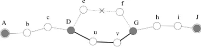
Fig. 3 shows an example in which the original path for segmentDGisDefGand the link betweeneandf breaks. An intrasegment route discovery succeeds and the new path for the segmentDGisDuvG. During the period from initiating the intrasegment route repair to knowing the result of the repair, the initiator buffers data packets it receives that use the route under repair. If the intrasegment repair succeeds, the initiator transmits the buffered data packets; otherwise, it tries intersegment repair and keeps buffering undeliverable data packets.
Intrasegment route repair tries to establish a new path between the start and the end nodes of a broken segment. It may also establish a new path for the previous segment, even if the previous segment is not broken. The reason is
that in AODV nodes learn new routes from route request messages—a node that receives a RREQ inserts or updates a route to the RREQ initiator. When theRREQintramessage is
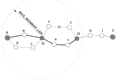
broadcast from the initiator, the previous segment is in the range of the intrasegment route discovery. Fig. 4 shows that an intrasegment route repair at the segmentDGalso builds a new path for the previous segmentAD. The old segment AbcDis replaced with a new segment,AwE. When a new path is discovered for the previous segment, it may be not activated. Therefore, the start node of the previous segment sends a RACT message to the initiator to activate the new path. The intrasegment route repair that happened at the broken segment is also helpful to update the previous segment.
If the intrasegment route repair succeeds (simulations show that in most cases it does), the waypoint nodes on the repaired route will not be changed and the source node will not be notified because data packets can be forwarded along the same waypoint nodes. If the intrasegment route repair fails, the initiator will try the intersegment route repair, as described next.
3.3.2 Intersegment Route Repair
The initiator knows the failure of an intrasegment route repair by using a timer called Intra_CheckReplied, which is set when the intrasegment route repair is initiated. If the timer expires and no path to the end node of the broken segment exists, the initiator concludes an unsuccessful intrasegment route repair and starts an intersegment route repair. Briefly, the process of the intersegment route repair includes discovering routes to downstream waypoint nodes on the route, repairing the broken route if the route discovery succeeds, and sending the repair result to the source.
Before explaining the detailed repair process, we intro-duce the definition of the intersegment route error (RERRinter) message in DOA. As described above, several
types of information, such as whether the repair is successful or not, are required by upstream waypoint nodes. We utilize theRERRintermessage to carry different
information. A RERRinter message can be any of the
following three types:
REPAIR: It informs that the route was broken, and the intersegment route repair succeeded. The repaired route is contained in the message.
BROKEN:It informs that the route was broken and the intersegment route repair failed. The source node may need to start another global route discovery.
LOOP: It removes a loop on the route. This type of RERRinter message is used for loop detection and will be
explained in Section 3.4 in detail.
We denote these three types ofRERRinter messages as
RERRrepairinter,RERRbroken
inter andRERR loop
inter, respectively.
As for the details of the intersegment route repair, the initiator starts a localized intersegment route discovery by broadcasting aRREQintermessage. The discovery process is
similar to the global intersegment route discovery discussed in Section 3.1. While the intrasegment route repair discovers a path to the end node of the broken segment in the range of one segment (MAX SEGMENT LEN), the intersegment route repair discovers a path to the end node of the segment after the broken segment in the range of two segments (2MAX SEGMENT LEN). If the broken seg-ment is the last segseg-ment of the route, the target of the route discovery will be the destination.
Upon receiving the RREQinter message, intermediate
nodes handle the message as described in Section 3.1.1. The
RREQinteris propagated if it is not a duplicate and its TTL is
greater than zero. When the target receives theRREQinter, it
divides the path recorded in theRREQinterinto segments if
the path is longer than DEFAULT_ SEGMENT_LEN hops. The target sends an intersegment route reply (RREPinter) to
the initiator. After receiving the RREPinter, the initiator
repairs the route by replacing the broken segment and a few old downstream segments, which are no longer used by the repaired route, with the new segments returned by the
RREPinter. Then the initiator updates its route cache, sends
aRERRrepairinter message containing the repaired route to the source through upstream waypoint nodes, and transmits buffered data packets using the repaired route. Upon receiving theRERRrepairinter , upstream waypoint nodes update their route cache and transmit buffered data packets using the repaired route.
We illustrate the process of the intersegment route repair by using the following example. The original route from the sourceAto the destinationLis
AbcDefGhiJkL:
It can be written as ADGJL at the interseg-ment level. Suppose seginterseg-ment DG is broken, denoted as ADGJL. Node D is the initiator of the route repair. The intrasegment route repair was attempted first to discover a path for segment DG, but it failed. Next, node D tries the intersegment route repair to discover a path to the end node J of next segment GJ. Node D initiates a localized intersegment route discovery and the target is J. Suppose the route discovery succeeds and the new path from Dto J is
DuvWxyJ:
NodeW is selected as a waypoint node because the hop count from Dto J is greater than DEFAULT_SEGMENT_ LEN (its value is 3) and the path fromDtoJis divided into
two segments. InitiatorDrepairs the original route and the repaired route is
AbcDuvWxyJkL:
It can be written asADWJLat the intersegment level. NodeDupdates its route cache, particularly, remov-ing routes DG, DGJ, and DGJL, and adding routes DW, DWJ, and DWJL. Then, D sends a RERRrepairinter message to source node A,
informing that the intersegment repair succeeded and the repaired route fromAtoLisADWJL. Upstream waypoint nodes update their route caches similarly. Buf-fered and new data packets will be transmitted using the repaired route.
The initiator sets a timer called Inter_CheckRepliedwhen initiating an intersegment route repair. If no RREPinter is
received when the timer expires, the initiator concludes that the intersegment route repair has failed. The initiator then sends a RERRbroken
inter to the source through upstream
waypoint nodes, informing that the route is broken and route repairs (intrasegment and intersegment) have failed. Upstream waypoint nodes delete routes that use the broken segment from their route caches. Buffered data packets at waypoint nodes during route repairs are deleted. The source node may start another global intersegment route discovery to establish a route to the destination.
3.3.3 Multitarget Route Discovery
During the process of an intersegment route repair, the initiator conducts a localized intersegment route discovery to find a path to the end node of the next segment. It is possible that end nodes of other downstream segments are located in the discovery range. This is for two reasons. First, this discovery covers the range of two segments, which is larger than an intrasegment route discovery that covers one segment. Second, these nodes may move into the range because of the mobility. If these nodes send replies to the initiator, the intersegment route discovery will be more likely to succeed and may result in a shorter route (fewer number of segments) than the original route. This is the motivation for the multitarget route discovery.
In a multitarget route discovery, the target field of the intersegment route request ðRREQinter) message may
contain more than one node ID, which means the initiator tries to find paths to multiple targets simultaneously. In DOA, aRREQintermessage can contain up to three targets: the end nodes of the next two segments after the broken segment, and the destination.
In our previous example, segment DGon route fromA to L is broken (ADGJL) and node D is the initiator for the intersegment route repair. When multitarget route discovery is used, the RREQinter message that D broadcasts contains J (the end node of the next segment) andL(the destination) in the target field. BothJandLcan send replies toDupon receiving theRREQinter message.
3.4 Routing Loops Detection and Handling
Because local route repair operates within a limited range and lacks global knowledge, it may create routing loops. A routing loop is harmful for MANETs because it wastes resources such as bandwidth, processing power, battery,
memory, etc. Therefore, loop freedom is one of the key requirements for all ad hoc routing protocols.
If a loop exists, the route would pass an intermediate node more than once. We call this node theloop node. If a loop existed on a route found using DOA, it would involve either one segment or multiple segments, which we term
intrasegment loop and intersegment loop, respectively. An intrasegment loop is not possible since AODV is used for the intrasegment routing and the loop-free characteristic is ensured by the sequence number mechanism.
For an intersegment loop, the loop node belongs to at least two segments on a route. Three cases are possible:
Case 1:The loop node appears more than once in a source route that contains only waypoint nodes. This type of loop is easy to detect because source routing is used at the global level. During intersegment route discovery, an intermediate node will not handle an RREQinter if it finds that its own
address is already present in the recorded path. When forwarding data packets, waypoint nodes are explicitly carried in the headers of data packets and duplicate waypoint nodes can be easily detected.
Case 2:The loop node is a forwarding node of one segment on the route and is either a forwarding node or a start node of another segment on the route. This is a difficult situation and needs to be specially taken care of.
Case 3:The loop node is a forwarding node of one seg-ment on the route and is also the destination of the route. This situation is possible when the destination moves toward the source and becomes a forwarding node of an upstream segment during route repairs. This situation does no harm because once the network layer finds the destination address of data packets that match its own address, it will stop routing the packets and send them to the higher layer.
We designed a simple and efficient method to detect loops belonging to Case 2 and Case 3:
Loop Detection: Upon receiving a data packet, an inter-mediate node checks its intrasegment routing table (hend node:next hopistructure. If it has routes (next hop) to the end node of the current segment as well as to the end node of another downstream segment, then a loop belonging to Case 2 or Case 3 exists.
If a node finds a loop on a route, it removes the loop by changing the target (end node) of the intrasegment routing. It changes the target from the end node of the current segment to the end node of the downstream segment that it knows the next hop. If the number of hops between the original start node and the new end node is larger than MAX_SEGMENT_LEN, the current node becomes a way-point node on the route after the loop is removed.
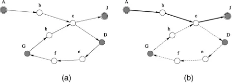
A loop belonging to Case 2 is shown in Fig. 5a. A path from sourceAto destinationJ is
AbcDefGhcJ:
loop by changing the target of intrasegment routing fromD to J. The new path becomes AbcJ, as shown in Fig. 5b.
A loop belonging to Case 3 can also be detected by the loop detection method. Suppose a path from source A to destination J is AbcDejGhiJ. NodeJis a forwarding node of segmentDGand is also the destination. Nodeedetects the loop because it knows next hops for end nodeGof the current segment as well as for end node J of segmentGJ. Nodeeremoves the loop and the new path becomesAbcDeJ.
If the node that removes a loop is not the source, it initiates a RERRloopinter message, which contains information about the location of the loop and the new waypoint node, if applicable. The message is sent to the source through upstream nodes. Upon receiving theRERRloopinter, upstream waypoint nodes remove the loop from their route caches and the source uses the modified route to transmit data packets thereafter.
3.5 Supporting Metrics Other Than Hop Count When choosing a path during a route discovery, hop count is the most commonly used metric. However, as pointed out by de Couto et al. [20], the minimum hop count metric performs poorly in their 802.11b testbed. This is because the hop count metric may fail to choose paths with high throughput. They proposed a new metric called expected transmission count (ETX) to solve the problem. Therefore, it will be desirable for WPR to support metrics such as ETX in addition to hop count. We will use ETX as a representative in the following discussion.
Inherently, a DSR-like routing protocol is suitable to use ETX because ETX needs to collect the metric of each link on the path. AODV will face problems when supporting ETX because its route request messages do not record the traversed links. Nevertheless, WPR is able to support ETX in the following ways:
First, WPR is a routing model that uses a high-level intersegment routing protocol and a low-level intrasegment routing protocol. Many existing routing protocols are eligible for WPR. To support ETX, the intersegment routing can use DSR, and the intrasegment routing can use DSDV or DSR, since ETX has been implemented for both DSDV and DSR in [20]. Thus, a global route discovery will find a least-ETX path from a source to a destination and a local route repair will find a least-ETX path between two waypoint nodes.
Second, in the case of DOA, the global route discovery and the intersegment route repair are able to support ETX
easily, because they work in source routing manner. The only problem is the intrasegment route repair, which conducts an AODV-style local route discovery. Then, the problem becomes whether AODV can support ETX. We designed a mechanism for AODV to use ETX-like metrics in [21]. Due to space limitations, we could not give the details in this paper.
4
P
ERFORMANCEE
VALUATION4.1 Simulation Setup
We conducted extensive simulations to evaluate the performance of DOA and compare it with AODV and DSR. The simulations were implemented on GloMoSim 2.03 [22], a scalable simulation environment for wireless net-work systems. GloMoSim uses the parallel discrete-event simulation capability provided by PARSEC [23].
The MAC layer protocol used in the simulations was the IEEE standard 802.11 Distributed Coordination Function (DCF) [24]. DCF uses Request-to-Send (RTS) and Clear-to-Send (CTS) control packets for unicast data transmissions. Broadcast data packets and RTS control packets are sent using the unslotted Carrier Sense Multiple Access protocol with Collision Avoidance (CSMA/CA) [24]. The simula-tions used the two ray propagation model, 2 Mb/sec radio bandwidth, and 250m radio range.
The traffic was constant bit rate (CBR). The source and the destination of each CBR flow were randomly selected but not identical. Each flow did not change its source and destination for the lifetime of a simulation run. Each source transmitted data packets at a rate of four 512-byte data packets per second. The mobility model was random waypoint with the speed ranging from 0 m/s to 10 m/s and a pause time of 30 seconds. Exceptions will be noted otherwise.
We conducted three sets of simulations to evaluate the performance of DOA. First, we studied the scalability of DOA in networks with 100 to 1,400 nodes. Second, we studied the performance of DOA when it worked in the DSR and AODV modes. The number of CBR flows was 20 in both the simulation sets. Finally, we studied the performance of DOA when the number of flows increased from 20 to 60 in networks with 400 nodes. In the simulations, we collected data for five metrics, namely, control overhead, packet delivery ratio (PDR), end-to-end delay, average route length, and route repair success ratio. The first three metrics were evaluated in all simulation sets. The average route length metric was evaluated in the first and second sets, and the metric of route repair success ratio was evaluated in the first set.
When simulating DSR, we did not enable route replies from intermediate nodes, because the performance would become worse otherwise. The reason is that the implemen-tation of DSR in GloMoSim 2.03 does not have a timeout mechanism to eliminate stale routes from route caches. We did not compare DOA with CGSR, ZRP, and LANMAR because DOA will incur much less routing overhead than CGSR, ZRP, and LANMAR. The latter maintain hierarchies proactively for all nodes in the network, while DOA
maintains the hierarchy reactively and only for nodes on active routes.
Each data point in the graphs is averaged over 10 simula-tion runs, each with a different seed. Each simulasimula-tion lasted for 600 seconds. Each source used a warm-up time, randomly selected from 60 to 100 seconds before transmis-sion of data packets started, and ended transmitting data packets 20 seconds (cool-down time) before the simulation finished. Most of the time, the flows in our simulations ran concurrently, instead of sequentially. We set the system parameters MAX_REPLY_TIMES, DEFAULT_SEGMENT_ LEN and MAX_SEGMENT_LEN to 2, 3 and 4, respectively.
4.2 Results and Analysis
4.2.1 Scalability Study
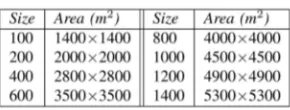
In this set of simulations, we studied the performance of DOA when the network size varied from 100 nodes to 1,400 nodes. The network sizes and the respective network areas are shown in Table 1. The size and the area were selected so that the node density was approximately constant, which would properly reflect the scalability of routing protocols. For each performance metric, we com-pared DOA with DSR and AODV. The results are shown in Figs. 6a, 6b, 6c, 6d, and 6e.
Control Overhead.The main purpose of using hierarchy in MANETs is to reduce the routing overhead. Fig. 6a shows the control overhead of DOA, DSR, and AODV. We observe that DOA has much less control overhead than AODV when the network size increases while supporting
high PDR (Fig. 6b). For networks with 100 nodes, three protocols incur approximately the same amount of control overhead; for networks with 600 nodes, DOA saves 68 percent control packets compared to AODV; for net-works with 1,400 nodes, DOA saves 80 percent control packets compared to AODV. The larger the network size is, the more control packets are saved by DOA. DSR incurs slightly less control overhead than DOA. However, the PDR of DSR is much less than DOA and AODV (Fig. 6b).
Control overhead in DOA is significantly reduced because of the use of the waypoint routing hierarchy. WPR enables the localization of route maintenance activ-ities. For example, a broken route can be repaired at the intrasegment level or at the intersegment level. The low control overhead is critical for DOA to scale to large MANETs.
Three optimizations to AODV have been studied [25] (which will be discussed in Section 5), including expanding ring search, query localization, and local repair. These optimizations can be incorporated in DOA to reduce the intrasegment routing overhead further.
Packet Delivery Ratio.Fig. 6b shows the PDRs of DOA, DSR, and AODV. We observe that DSR cannot scale to networks beyond a few hundred nodes. For networks with 600 nodes, DSR delivers 50 percent data packets. On the other hand, both DOA and AODV show high PDRs even for networks with more than 1,000 nodes. For all network sizes from 100 nodes to 1,400 nodes, DOA consistently delivers about 2 percent-3 percent more data packets than AODV.
DOA maintains routes hierarchically and repairs a broken route locally. Thus, an active route in DOA usually lasts longer and more data packets can be delivered. AODV shows very comparable PDR to DOA. However, the control overhead of AODV is significantly higher. DSR does not scale well because it has higher packet header overhead and keeps routing information in nondistributed manner, as discussed in Section 2.1.
TABLE 1
Network Sizes and Network Areas
End-to-End Delay.Fig. 6c shows the average end-to-end delay of DOA, DSR, and AODV. DOA exhibits the lowest end-to-end delay most of the time. The end-to-end delay of AODV is very comparable to DOA, while DSR has much higher end-to-end delay than the other two protocols.
In DOA, we expect a smaller end-to-end delay because the route repair mechanism recovers a broken route quickly and data packets do not have to wait for another round of route discovery before they can be transmitted. However, DOA may not reduce the end-to-end delay dramatically for the following reasons: Data packets are buffered at intermediate waypoint nodes when a broken route is being repaired and the buffer time contributes to the end-to-end delay. In the worst case, if the route repair fails, the time spent for the local repair will be wasted.
The end-to-end delay in the figure does not show an obviously increasing trend. The main reason for that is that we used a constant number of CBR sources. In smaller networks, the average length of routes is shorter but the networks are more congested; in larger networks with the same node density, the average length of routes is longer but the networks are less congested.
Route Repair Success Ratio. Fig. 6d shows the success ratios of intrasegment route repairs and intersegment route repairs in DOA. We observe that both success ratios are very high. More than 80 percent of intrasegment and intersegment route repairs succeed for all network sizes. These results show that both intrasegment and interseg-ment route repairs are worthwhile. The results also verify our discussion in Section 1 that when a route breaks, usually only a few hops are broken but other hops are still intact. By repairing the broken route locally, we extend the lifetime of the route and reduce the number of global route discoveries.
Average Route Length. One concern for using local route repairs is that the repaired route may be suboptimal. In the worst case, it may create a routing loop. In DOA, a route can not become very suboptimal for the following reasons. First, if a forwarding node moves away, it will cause a link break and intrasegment route repair will eliminate it from the current segment. The new route between the start and the end nodes of the broken segment will become optimal again after the repair. Second, if a waypoint node moves away, it will cause a segment breakage and the intrasegment route repairs may increase the hop count of the segment. But, eventually, intrasegment route repair will fail in the TTL range of MAX_SEGMENT_ LEN hops. Then, intersegment route repair is tried and it
usually will eliminate the leaving waypoint node from the route. Finally, our loop detection mechanism effectively detects loops on active routes and removes them.
Fig. 6e supports our analysis. The average route lengths of DOA and AODV are very comparable. Even for networks with 1,400 nodes, the average route length of DOA (14.77 hops) is only 0.95 hop longer than that of AODV (13.82 hops).
The above results (Figs. 6a, 6b, 6c, 6d, and 6e) show that DOA indeed incorporates good aspects of DSR and AODV and exhibits promising performance, especially in medium to large networks. Particularly, DOA substantially reduces the control overhead compared to AODV, and delivers significantly more data packets than DSR. At the same time, DOA maintains low end-to-end delay and short average route length after applying intrasegment and intersegment route repairs. The repairs successfully recover a broken route most of the time.
4.2.2 DSR and AODV Modes
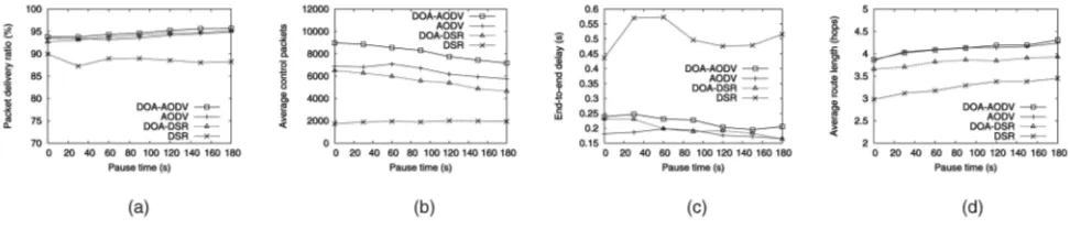
As mentioned in Section 1, DSR and AODV are two special cases of DOA. When the segment length is set to 1, DOA works in DSR mode; when the segment length is set to a large number, DOA works in AODV mode. This set of simulations aimed to test how well DOA works in DSR and AODV modes, which are denoted as DSR and DOA-AODV, respectively. The simulations were run on networks with 100 nodes in the area of 1;4001;400 m2 and with pause time varying from 0 to 180 seconds. The segment length is set to 64 when simulating DOA in AODV mode. Other settings are the same as in the previous simulations. For each performance metric, we compared DOA-DSR and DOA-AODV with pure DSR and AODV. The results are shown in Figs. 7a, 7b, 7c, and 7d.
Fig. 7a shows the PDRs of four protocols. We observe that DOA-DSR, DOA-AODV, and AODV all show high and very comparable PDRs (around 94 percent), while the PDR of DSR is lower (less than 90 percent). The improvement of DOA-DSR compared to DSR mainly comes from inter-segment route repairs.
Fig. 7b shows the control overhead of four protocols. DOA-DSR and DOA-AODV incur more control overhead than DSR and AODV, respectively. This is expected because DOA-DSR (DOA-AODV) needs more control messages than DSR (AODV) to maintain the hierarchy for active routes. DSR has the lowest control overhead because it uses promiscuous listening mode. DOA will exhibit performance advantage when the network size increases.
Fig. 7c shows the end-to-end delays of four protocols. The end-to-end delays of DOA-DSR, DOA-AODV, and AODV are approximately the same (around 0.2 second), while the end-to-end delay of DSR is around 0.5 second, which is higher than other protocols. This is because in DSR, routes are contained in data and control packets, which increases packet sizes and, thus, incurs more transmission time.
Fig. 7d shows the average route lengths of four protocols. The average route lengths of DOA-DSR, DOA-AODV, and AODV are approximately equal, while the metric of DSR is about one hop less.
The above results (Figs. 7a, 7b, 7c, and 7d) show that the performance of DOA-AODV is comparable to that of pure AODV, while the performance of DOA-DSR is better than that of pure DSR in terms of packet delivery ratio and end-to-end delay. The good performance of DOA in AODV and DSR modes is important, because it makes DOA very flexible—applications that need AODV or DSR routing can coexist in networks using DOA.
4.2.3 Varying CBR Flows
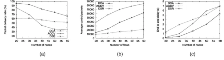
This set of simulations aim to study the performance of DOA when the number of CBR flows increases. The simulations were run on networks with 400 nodes in the area of 2;8002;800 m2. The number of CBR flows increased from 20 to 60. Other settings are the same as in previous simulations. For each performance metric, we compared DOA with DSR and AODV. The results are shown in Figs. 8a, 8b, and 8c.
Fig. 8a shows the PDRs of three protocols. The PDRs drop as the number of flows increases because the network becomes more congested. Nevertheless, DOA still shows the highest PDR. When the number of flows is 60, the PDR of DOA is 66 percent, while the PDRs of DSR and AODV are 52 percent and 34 percent, respectively. The PDR of DSR does not drop too much because DSR uses promiscuous listening mode, which we will explain in more detail when discussing the next figure.
Fig. 8b shows the control overhead of three protocols. We observe that DOA consistently saves more than
2104 control packets per flow compared to AODV. However, when compared to DSR, DOA incurs more overhead. This is mainly because DSR uses promiscuous listening mode. Under this mode, when more traffic exists in the network, a node has more chances to learn new routes and thus conducts less route discoveries. We
did not use promiscuous listening mode in DOA because it would consume significantly more CPU and battery.
Fig. 8c shows the end-to-end delays of three protocols. We observe that DOA incurs the lowest end-to-end delay among three protocols. The end-to-end delay of AODV is lower than DSR when the number of flows is less than 50, and becomes comparable to DSR after that.
The above results (Figs. 8a, 8b, and 8c) show that DOA works well when the number of data flows increases in the network. DOA performs best among three protocols in terms of PDR and end-to-end delay. DSR incurs less control overhead at the cost of working in promiscuous mode.
5
R
ELATEDW
ORKWe first briefly review DSR and AODV because they are two well-known on-demand routing protocols for MANETs and they are combined hierarchically in DOA. We then review three hierarchical routing protocols that are related to our work: CGSR, ZRP, and LANMAR. Finally, a dynamic addressing scheme to achieve scalability is presented.
DSR [6] uses a source routing approach in which the source node explicitly designates the route to the destina-tion in the headers of data packets. Routes are obtained by recording paths in RREQ messages and returning the paths in RREP messages.
AODV [7] is based on a traditional distance vector routing mechanism, where the route is determined on a hop-by-hop basis. The route is established by leaving a backward route to the source at intermediate nodes when propagating RREQ messages and by leaving a forward route to the destination at intermediate nodes when relaying the RREP message to the source.
Lee et al. [25] studied three optimizations to AODV. These optimizations include an expanding ring search for route discoveries, a query localization protocol to prevent the flooding of route requests, and a local repair of link breaks on active routes. Since we use AODV as the intrasegment routing protocol in DOA, these optimizations can be utilized to reduce the overhead of intrasegment routing.
Clusterhead-Gateway Switch Routing (CGSR) [8] is based on the Destination-Sequenced Distance-Vector (DSDV) [26] routing protocol and works proactively. CGSR organizes the network intoclustersand elects aclusterheadin each cluster by running the Least Clusterhead Change (LCC) clustering algorithm. Other nodes in that cluster are one hop away from the clusterhead. Nodes that belong to
more than one cluster aregateways. Each node maintains a
cluster member table and a distance vector table. The cluster member table records which cluster each node belongs to by storing the clusterhead of that cluster, while the distance vector table records next hops (usually gateways) to all clusters. CGSR reduces the size of the routing table by maintaining a route entry for each cluster instead of an entry for each node. Typically a route in CGSR is of the formclusterheadgatewayclusterhead, and so on.
The Zone Routing Protocol (ZRP) [10] is a hybrid routing protocol. Each node dynamically maintains azonecentered at itself. A zone is a collection of neighbors and links within a predefined number of hops, which is termed the zone radius. IntrAzone Routing Protocol (IARP) works proac-tively and is used for the routing inside the zone, while IntErzone Routing Protocol (IERP) works reactively and is used for the routing outside the zone. To establish a route to the destination outside the source’s zone, RREQ/RREP is used like other on-demand routing protocols. Bordercast Resolution Protocol (BRP) [10] is designed to reduce the overhead of the RREQ by forwarding the request recur-sively to border nodes, to which the hop count equals to zone radius, until one node that has the destination in its zone is reached.
Landmark Ad Hoc Routing Protocol (LANMAR) [27] is designed for MANETs that exhibit group mobility. LAN-MAR combines the features of Fisheye State Routing (FSR) [28] and Landmark routing [29]. LANMAR groups the network into logical subnets consisting of nodes that have common interests and move as a group. Alandmarknode is dynamically elected as the representative of each subnet. FSR is running as the underlying routing scheme. Each node maintains two routing tables: alocal routing table for nodes within the subnet and alandmark tablethat maintains distance vectors for all landmarks. The landmark informa-tion is carried in the header of the data packet. If the destination is within a node’s subnet, the node forwards the packet using the local routing table. Otherwise, the packet will be forwarded toward the landmark by using the landmark table. When the packet reaches the subnet that contains the destination, it is routed using local routing table, possibly not going through the landmark node.
CGSR routes packets through clusterheads, which creates bottlenecks for network resources such as band-width and battery power. In DOA, although waypoint nodes take more responsibility than forwarding nodes, a node that is a waypoint node for one route may be a forwarding node for another route. Therefore, the nodes in a network are likely to work uniformly. CGSR, ZRP, and LANMAR all maintain the hierarchies (cluster, zone, or subnet) proactively, which may cause large overhead in a mobile environment, while our protocol maintains the hierarchy reactively and for active routes only.
Eriksson et al. [30] proposed a dynamic addressing scheme to solve the scalability problem in MANETs. In their work, traditional IP address is used only for identification purpose, not for routing. A routing address is introduced to reflect the node’s location in the network topology. Routing addresses are organized into a tree and might be dynami-cally changing due to node mobility. A range of routing
addresses with a common prefix form a subtree, with the fundamental constraint that the nodes of a subtree form a connected subgraph in the network topology. The scal-ability relies on the balancing of the routing address tree. But in a mobile environment, the tree may get unbalanced and the operation to optimize/balance the tree could be complicated and expensive.
6
C
ONCLUSIONWe proposed a new routing model, Way Point Routing (WPR), which maintains active routes hierarchically for Mobile Ad Hoc Networks (MANETs). WPR divides an active route into segments by selecting a number of nodes on the route as waypoint nodes. An intersegment routing protocol runs globally, while an intrasegment routing protocol runs locally. Thus, route maintenance can be localized to one or a few neighboring segments. One distinct advantage of WPR is that when a route is broken because of node mobility or node failure, instead of discarding the whole route and discovering a new route from the source to the destination, only the two waypoint nodes of the broken segment need to find a new segment. This will have a clear performance advantage in terms of routing overhead, end-to-end delay, etc.
We presented an instantiation of WPR termed DSR over AODV (DOA). In DOA, DSR is used for intersegment routing and AODV is used for intrasegment routing. This is the first work to combine DSR and AODV, two well-known on-demand routing protocols, in a hierarchical manner. We also presented two novel techniques for route maintenance in DOA: a multitarget route discovery and an efficient loop detection method. We conducted extensive simulations to evaluate the performance of DOA. We compared DOA with AODV and DSR. Simulation results show that DOA scales well for networks with more than 1,000 nodes, routing overhead is significantly reduced, while other metrics are better or comparable to AODV and DSR.
Our future work includes utilizing heuristic methods to select waypoint nodes, e.g., selecting nodes with lower speed; using common waypoint nodes for different active routes to facilitate the hierarchy maintenance; securing the WPR routing model and particularly DOA routing protocol; and considering other routing protocols for intersegment routing and intrasegment routing in WPR.
A
CKNOWLEDGMENTSThe authors would like to acknowledge Venkata C. Giruka, Yongwei Wang, and Qiangfeng Jiang for their valuable discussions and suggestions.
R
EFERENCES[1] ExScal Project, http://www.cast.cse.ohio-state.edu/exscal/, 2005.
[2] Terminodes Project, http://www.terminodes.org/, 2005.
[3] Roofnet Project,” http://pdos.csail.mit.edu/roofnet/, 2005.
[4] E. Royer and C. Toh, “A Review of Current Routing Protocols for Ad Hoc Mobile Wireless Networks,”IEEE Personal Comm.,pp. 46-55, Apr. 1999.