Architecture, Mobility and Services
Second Edition
Heikki Kaaranen
Oy Aqua Records Ltd, Finland
Ari Ahtiainen
Nokia Research Center, Finland
Lauri Laitinen
Nokia Research Center, Finland
Siama¨k Naghian
Nokia Networks, FinlandValtteri Niemi
Nokia Research Center, Finland
Architecture, Mobility and Services
Second Edition
Heikki Kaaranen
Oy Aqua Records Ltd, Finland
Ari Ahtiainen
Nokia Research Center, Finland
Lauri Laitinen
Nokia Research Center, Finland
Siama¨k Naghian
Nokia Networks, FinlandValtteri Niemi
Nokia Research Center, Finland
Email (for orders and customer service enquiries): [email protected] Visit our Home Page on www.wiley.com
All Rights Reserved. No part of this publication may be reproduced, stored in a retrieval system or transmitted in any form or by any means, electronic, mechanical, photocopying, recording, scanning or otherwise, except under the terms of the Copyright, Designs and Patents Act 1988 or under the terms of a licence issued by the Copyright Licensing Agency Ltd, 90 Tottenham Court Road, London W1T 4LP, UK, without the permission in writing of the Publisher. Requests to the Publisher should be addressed to the Permissions Department, John Wiley & Sons Ltd, The Atrium, Southern Gate, Chichester, West Sussex PO19 8SQ, England, or emailed to [email protected], or faxed to (þ44) 1243 770620
Designations used by companies to distinguish their products are often claimed as trademarks. All brand names and product names used in this book are trade names, trademarks or registered trademarks of their respective owners. The Publisher is not associated with any product or vendor mentioned in this book.
This publication is designed to provide accurate and authoritative information in regard to the subject matter covered. It is sold on the understanding that the Publisher is not engaged in rendering professional services. If professional advice or other expert assistance is required, the services of a competent professional should be sought.
Other Wiley Editorial Offices
John Wiley & Sons, Inc., 111 River Street, Hoboken, NJ 07030, USA Jossey-Bass, 989 Market Street, San Francisco, CA 94103-1741, USA Wiley-VCH Verlag GmbH, Boschstr. 12, D-69469 Weinheim, Germany
John Wiley & Sons Australia Ltd, 33 Park Road, Milton, Queensland 4064, Australia
John Wiley & Sons (Asia) Pte Ltd, 2 Clementi Loop #02-01, Jin Xing Distripark, Singapore 129809 John Wiley & Sons Canada Ltd, 22 Worcester Road, Etobicoke, Ontario, Canada M9W 1L1
Wiley also publishes its books in a variety of electronic formats. Some content that appears in print may not be available in electronic books.
British Library Cataloguing in Publication Data
A catalogue record for this book is available from the British Library
ISBN 0-470-01103-3
Project management by Originator, Gt Yarmouth, Norfolk (typeset in 10/12pt Times). Printed and bound in Great Britain by Antony Rowe Ltd, Chippenham, Wiltshire. This book is printed on acid-free paper responsibly manufactured from sustainable forestry in which at least two trees are planted for each one used for paper production.
Preface xi
Acknowledgements xv
PART ONE 1
1 Introduction 3
1.1 Specification Process for 3G 5
1.2 Introduction to the 3G Network Architecture 8
1.2.1 Conceptual Network Model 8
1.2.2 Structural Network Architecture 9 1.2.3 Resource Management Architecture 11
1.2.4 Bearer Architecture 13
2 Evolution from GSM to UMTS Multi-access 15
2.1 From Analogue to Digital 16
2.2 From Digital to Reachability 18
2.3 Jump to Packet World and Higher Speeds 19
2.4 3GPP Release 99 21
2.5 3GPP Release 4 24
2.6 3GPP Release 5 25
2.7 Trends beyond 3GPP Release 5 26
PART TWO 29
3 The Key Challenges Facing the Mobile Network Architecture 31
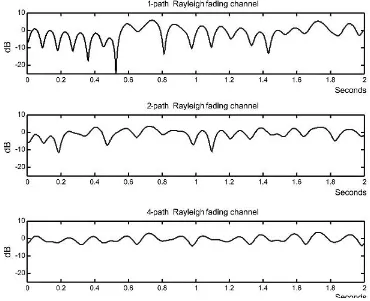
3.1 Radio Communication Constraints 31
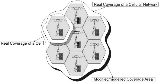
3.2 Cellular Radio Communication Principles 36
3.3 Multi-access Techniques 39
3.4 Device Mobility 44
3.5 Network Transport 45
3.6 Transport Alternatives for UMTS 46
3.6.1 Asynchronous Transfer Mode in UMTS 48
3.6.2 IP Transport 49
3.7 Network Management 51
3.7.1 High-level Architecture of a Network Management System 51
3.8 Spectrum and Regulatory 53
3.8.1 UMTS Spectrum Allocation 56
4 Overview of UMTS Radio Access Technologies 59
4.1 WCDMA Essentials 59
4.2.2 The Benefits and Impacts 76
4.2.3 Basic Concept 78
4.2.4 Adaptive Modulation and Coding 78 4.2.5 Hybrid Automatic Repeat Request 80
4.2.6 Fast Scheduling 80
4.2.7 Seamless Cell Change 81
4.2.8 Basic Operation and Architectural Considerations 81
4.3 GSM/EDGE 83
4.3.1 Basic Concepts 83
4.3.2 Radio Channels and Frame Structures 85 4.3.3 General Packet Radio Service (GPRS) 89 4.3.4 Enhanced Data Rates for Global/GSM Evolution (EDGE) 91
4.4 WLAN Technology 93
4.4.1 Physical Technology 93
4.4.2 Medium Access Control 94
4.4.3 Network Formation 97
5 UMTS Radio Access Network 99
5.1 UTRAN Architecture 100
5.2 Base Station (BS, Node B) 101
5.2.1 Base Station Structure 101
5.2.2 Modulation Method 103
5.2.3 Receiver Technique 106
5.2.4 Cell Capacity 108
5.2.5 Control Functions in BS 110
5.3 Radio Network Controller (RNC) 110
5.3.1 Radio Resource Management (RRM) 112
5.3.2 UTRAN Control Functions 134
6 UMTS Core Network 143
6.1 UMTS Core Network Architecture 145
6.1.1 Core Network Entities that Are Common to All Domains and
Subsystems 146
6.1.2 CS Domain 148
6.1.3 PS Domain 150
6.2 CN Management Tasks and Control Duties 152
6.2.1 Mobility Management (MM) 153
6.2.2 Communication Management (CM) 167
6.3 Charging, Billing and Accounting 173
6.3.1 Charging and Accounting 173
6.3.2 Billing 176
6.4 IP Multimedia Subsystem (IMS) 180
6.5 IP Multimedia Subsystem Fundamentals 181
6.6 IMS Entities and Functionalities 185
6.6.1 Call Session Control Functions (CSCFs) 185
6.6.2 Databases 188
8 Services in the UMTS Environment 207
8.1 About Services in General 207
8.1.1 What Do Users Really Want? 208
8.1.2 How Can We Make Money out of This? 209 8.1.3 What Are the Most Adequate Design Principles in a Complex
System? 210
8.1.4 Do Service-related Facts in Mobile Networks Differ from
Those in Fixed Networks? 211
8.2 Quality of Service (QoS) 211
8.2.1 Traffic Classes and QoS Attributes 211
8.2.2 About QoS Mechanisms 216
8.2.3 ReSerVation Protocol (RSVP) 217
8.2.4 Differentiated Services (DiffServ) 218 8.2.5 Multi Protocol Label Switching (MPLS) 219
8.3 About Service Subsystems 221
8.3.1 Services Inherited from the GSM 221
8.3.2 UMTS SIM Application Toolkit (USAT) 223
8.3.3 Browsing Facilities 224
8.3.4 Location Communication Services (LCS) 226 8.3.5 IMS Service Mechanism—Messaging 248 8.3.6 IMS Service Mechanism—Presence 249
8.4 Conclusions 251
9 Security in the UMTS Environment 253
9.1 Access Security in UMTS 254
9.1.1 Legacy from 2G 255
9.1.2 Mutual Authentication 256
9.1.3 Cryptography for Authentication 258
9.1.4 Temporary Identities 261
9.1.5 UTRAN Encryption 262
9.1.6 Integrity Protection of Radio Resource Control (RRC)
Signalling 264
9.1.7 Summary of Access Security 266
9.2 Additional Security Features in 3GPP R99 266
9.2.1 Ciphering Indicator 266
9.2.2 Identification of the UE 266
9.2.3 Security for Location Services (LCSs) 268
9.2.4 User-to-USIM Authentication 268
9.2.5 Security in Universal Subscriber Identity Module (USIM)
Application Toolkit 268
9.3 Security Aspects at the System and Network Level 268
9.3.1 Typical Security Attacks 269
9.3.2 Overview of 3GPP Network Domain Security 271
9.3.3 IP Security (IPSec) 271
9.3.4 MAPSec 274
9.4 Protection of Applications and Services 274 9.4.1 IP Multimedia CN Subsystem (IMS) Security 275 9.4.2 Examples of Application-layer Security Mechanisms 279
9.4.3 Security for Session Layer 279
9.4.4 AAA Mechanisms 280
9.5 Lawful Interception 280
PART THREE 285
10 UMTS Protocols 287
10.3 Transport Network Protocols 297 10.3.1 Transport Network Protocol Architecture 297 10.3.2 WCDMA Physical Layer in the Uu Interface 299 10.3.3 Backbone Networking in Other Interfaces 300 10.3.4 UMTS Transport Network Protocols 308
10.4 Radio Network Protocols 318
10.4.1 Radio Network Control Plane 318
10.4.2 Radio Network User Plane 326
10.5 System Network Protocols 330
10.5.1 Non-Access Stratum Protocols 330 10.5.2 Control Plane between CN Nodes 339 10.5.3 The User Plane in the System Network 341 10.6 Summary of UMTS Network Protocols 341
10.7 Overview of IMS Protocols 345
11 Procedure Examples 351
11.1 Elementary Procedures 351
11.1.1 Paging 353
11.1.2 RRC Connection Set-up 354
11.1.3 Transaction Reasoning 356
11.1.4 Authentication and Security Control 357 11.1.5 Transaction Set-up with Radio Access Bearer (RAB) Allocation 358
11.1.6 Transaction 360
11.1.7 Transaction Clearing and RAB Release 360
11.1.8 RRC Connection Release 364
11.2 RRM Procedure Examples 364
11.2.1 Soft Handover—Link Addition and Link Deletion 364 11.2.2 SRNS Relocation—Circuit Switched 367 11.2.3 Inter-System Handover from UMTS to GSM—Circuit Switched 369
11.3 MM Procedure Examples 371
11.3.1 Cell Update 371
11.3.2 URA Update 373
11.3.3 Location Update to the CN CS Domain 373 11.3.4 Routing Area Update to the CN PS Domain 374
The world’s first public GSM call was made on 1 July 1991 in a city park in Helsinki, Finland. This event is now hailed as the birthday of second-generation mobile telephony. GSM has been an overwhelming success, which wasdifficult to predict at that early stage. In the past 10 years GSM has become a truly global system for mobile communications. We now have cellular phone penetration rates exceeding 70% in many countries and approaching 90% in the Nordic countries, while, globally, the number of mobile phones has already passed the number of fixed phones, exceeding an expected figure of 1.5 billion in the near future.
A decade later GSM has brought us to the early stages of the third-generation mobile communications system—the Universal Mobile Telecommunications System (UMTS). The first networks have begun operations and a new generation of fancy mobile phones has appeared. By the end of October 2004 some 50 UMTS commercial networks were open for business around the world.
UMTS networks are introducing a completely new, high bit-rate radio technology— Wideband Code Division Multiple Access (WCDMA)— for wide area use. Never-theless, the core network part of the UMTS system is firmly founded on the successful GSM network, which has evolved from the circuit-switched voice network into a global platform for mobile packet data services like short messaging, mobile Web browsing and mobile email access.
The latest estimates show that packet-switching traffic in mobile core networks will exceed circuit-switching traffic in the near future. This transition is enabled by the UMTS system, which makes it possible for network operators to provide equally robust circuit-switched and packet-switched domains to meet data speed and capacity demands. Most voice and time-critical data services may still use circuit-switching, while less time-sensitive data pass through the UMTS mobile packet core network.
multimedia data services, fuelled by the mobility and personalisation of users and their terminals.
This is a book about the way in which UMTS networks can be used as a third-generation platform for mobility and services. It aims to provide a comprehensive overview of the system architecture and its evolution and to serve as a guidebook to those who need to study specifications from the Third Generation Partnership Project (3GPP). The content of the book is divided into three parts.
The first part consists of Chapters 1 and 2, which serve as an executive summary of the UMTS system. Chapter 1 introduces the UMTS technical and service architecture and key system concepts. Chapter 2 is an illustrated history of mobile network evolu-tion from second-generaevolu-tion GSM to the first UMTS multi-access release and beyond to full IP mobility networks.
The second part consists of Chapters 3–9, which examine the radio technology aspects, radio access and core network as well as, to a certain extent, the terminal in more detail. It also explains the functions and services provided to end users. Chapter 3 on the key architecture design challenges of cellular networks provides an overview of the fundamental challenges facing cellular networks and the way they have been resolved, particularly in the UMTS network.
Chapter 4 presents an overview of UMTS access technologies, including the latest enhancements in WCDMA technology within the scope of 3GPP Release 5. In addition, it addresses the other access technologies, like GSM/EDGE and WLAN, as complementary components of the UMTS multi-access network.
Chapters 5 and 6 describe the functional split between controlling functions distrib-uted among the UMTS network elements in the radio access and core network parts. Chapter 7 provides an overview of UMTS user equipment, focusing on those aspects that are most visible to the rest of the UMTS network. In Chapter 8 the UMTS network is examined as a network for services. It addresses service realisation by describing Quality of Service (QoS) and giving some examples of services that can be brought about by UMTS. The advanced security solutions of the UMTS network are then discussed in Chapter 9.
The remaining chapters (Chapters 10 and 11) form the third part of the book. In these chapters we take a protocol-oriented view to describe the system-wide interworking between thedifferent architectural elements. Chapter 10 first elaborates on the basic UMTS protocol architecture and then introduces the individual system protocols one by one. Chapter 11 returns to the network-wide view of earlier chapters by showing selected examples of the system procedures that describe how transactions are carried out across UMTS network interfaces under the coordination of system protocols.
At such an early stage of third-generation mobile communications the success of UMTS will be further enhanced by the thousands of leading system and software engineers, content providers, application developers, system integrators and network operators. We hope this book will help all of them reach their targets and let them enjoy and benefit from the UMTS networking environment.
What’s New in the Second Edition?
Since the first edition of this book in 2001, much has happened in wireless commun-ications, in general, and in UMTS network development, in particular. The move towards a data-centric service has been gaining momentum; the UMTS network has become a reality in several countries; short-range radios, such as WLAN and Bluetooth, have become integral components of mobile phones; Internet usage has rapidly spread; and the marriage between mobile networks and IP has become ever more evident. These have all been realised in one way or another in the latest development of 3GPP Release 5. In this new edition we try to reflect these changes while taking care of the main objective of this book: to stay as a comprehensive text of UMTS system architecture. We have also received much invaluable feedback from the readers of the first edition of the book which has come from all four corners of the world. We are very grateful for these insightful comments and have taken them into account in the writing process of the second edition. The level of this feedback has made us confident that the original purpose of the book (i.e., to serve as a UMTS system architecture book) was well received by the readership. The first edition has also been used as a course book for many training sessions, institutes and universities. We have also tried to keep this aspect in mind while taking on board the feedback from readers. In addition, more effort has been made to assure the overall quality of the second edition. To achieve this, more attention has been paid to editing and proof-reading of the text by both the authors and the publisher.
In this edition, every chapter has been revised to reflect the development in 3GPP standards up to Release 5. Some chapters have been radically reorganised and enhanced. We can summarise the changes to the second edition as:
. The first edition considered the UMTS network as a single access that only recog-nised the WCDMA UTRAN access network, and all topics were written on this basis. This edition recognises the other access technologies as well. The role of basic GSM is made more prominent since it forms the basic coverage anyway. UTRAN has been addressed at the same level as before. Complementary accesses are briefly described because their interworking has become an integral part of 3GPP evolution.
. Chapters 1 and 2 have undergone minor editing changes and some figures have been modified to make them compatible with 3GPP R5.
. Due to these various accesses, Chapter 3 in the first edition has now been split into two new chapters (Chapters 3 and 4). Chapter 3 gives an overview of the radio network challenges that arise from radio communication constraints, device mobility, transport, network management and scarcity of the radio spectrum. The new Chapter 4 provides an overview of selected UMTS access technologies—WCDMA and its enhancements HSPDA, GSM/EDGE and WLAN.
. Chapter 7, Terminal, has not involved any marked changes and only IMS-related aspects have been added. Chapter 8, Services, has been completely rewritten.
. Chapters 9, 10 and 11 have been updated to 3GPP R5.
While writing the first edition ofUMTS Networksthe team of authors and contributors had the pleasure of following the exciting finalisation of UMTS system specifications. During production of the second edition we’re witnessing yet another exciting break-through, the rolling out of UMTS networks around the world. Many colleagues, both from Nokia and outside, provided valuable input and comments on various aspects of the book. We would in particular like to thank Seppo Alanara, Mika Forssell, Harri Holma, Kaisu Iisakkila, Tatjana Issayeva, Sami Kekki, Pekka Korja, Jan Ka˚ll, Juho Laatu, John Loughney, Atte La¨nsisalmi, Anna Markkanen, Tomi Mikkonen, Juha Mikola, Ahti Muhonen, Aki Niemi, Mikko Puuskari, Mikko J. Rinne, Ville Ruutu, Juha Sipila¨, Janne Tervonen, Mikko Tirronen, Ari Tourunen, Jukka Viale´n and Andrei Zimenkov.
The inspiring working environment and close contacts with the R&D and standard-isation programmes within Nokia were made possible by the following managers of those programmes: Kari Aaltonen, Heikki Ahava, Tapio Harila, Reijo Juvonen, Jari Lehmusvuori, Juhani Kuusi, Yrjo¨ Neuvo, Tero Ojanpera¨, Lauri Oksanen, Pertti Paski, Tuula-Mari Rautala, Tuomo Sipila¨, Jukka Soikkeli, Jari Vainikka and Asko Vilavaara. The publishing team led by Mark Hammond and Sarah Hinton at John Wiley & Sons, Ltd gave us excellent support in the production of the second edition of the book. Their hard-working spirit made it possible to keep the demanding schedule in the publication process. The invaluable editing effort by Bruce Shuttlewood and the team from Originator Publishing Services helped us to improve the readability and language format of the text.
We must not forget that this is a book about UMTS networks and that these networks are based on the joint design and engineering effort of many colleagues of ours; it was their joint expertise that made it happen. Without being able to list all the experts from the early 1990s, those in the 3GPP organisation and those otherwise involved in UMTS development, we would like to thank all of them for their dedicated work in creating a new era in mobile communications.
help in word-processing and the graphical design of many figures was invaluable in putting the manuscript together.
As we are committed to the continuous improvement of the book, the authors once again welcome any comments and suggestions for improvements or changes that could be implemented in future editions of this book. The email address for gathering such input isumtsnetworks@pcuf.fi
The authors ofUMTS Networks
Part One
1
Introduction
Ari Ahtianen, Heikki Kaaranen and Siama¨k Naghian
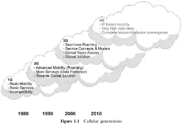
Nowadays, it is widely recognised that there are three different, implemented genera-tions as far as mobile communication is concerned (Figure 1.1). The first generation, 1G, is the name for the analogue or semi-analogue (analogue radio path, but digital switching) mobile networks established in the mid-1980s, such as the Nordic Mobile Telephone (NMT) system and the American Mobile Phone System (AMPS). These networks offered basic services for users and the emphasis was on speech and speech-related services. 1G networks were developed with national scope only and very often the main technical requirements were agreed between the governmental telecom oper-ator and the domestic industry without wider publication of the specifications. Due to national specifications, 1G networks were incompatible with each other and mobile communication was considered at that time to be some kind of curiosity and added value service on top of the fixed networks.
Because the need for mobile communication increased, also the need for a more global mobile communication system arose. International specification bodies started to specify what the second generation, 2G, mobile communication system should look like. The emphasis for 2G was on compatibility and international transparency; the system should be regional (e.g., European-wide) or semi-global and the users of the system should be able to access it basically anywhere within the region. From the end-user’s point of view, 2G networks offered a more attractive ‘‘package’’ to buy; besides the traditional speech service these networks were able to provide some data services and more sophisticated supplementary services. Due to the regional nature of standar-disation, the concept of globalisation did not succeed completely and there are some 2G systems available on the market. Of these, the commercial success story is the Global System for Mobile Communications (GSM) and its adaptations: it has clearly exceeded all the expectations set, both technically and commercially.
The third generation, 3G, is expected to complete the globalisation process of mobile communication. Again, there are national and regional interests involved and difficul-ties can be foreseen. Anyway, the trend is that 3G will mostly be based on GSM technical solutions for two reasons: GSM technology dominates the market and the great investments made in GSM should be utilised as much as possible. Based on this, the specification bodies created a vision about how mobile telecommunication will
develop within the next decade. Through this vision, some requirements for 3G were shortlisted as follows:
1. The system must be fully specified (like GSM) and major interfaces should be standardised and open. The specifications generated should be valid worldwide. 2. The system must bring clear added value to GSM in all aspects. However, at the start
the system must be backward-compatible at least with GSM and ISDN (Integrated Services Digital Network).
3. Multimedia and all of its components must be supported throughout the system. 4. The radio access of 3G must provide wideband capacity that is generic enough to become available worldwide. The term ‘‘wideband’’ was adopted to reflect the capacity requirements between 2G narrowband capacity and the broadband capacity of fixed communications media.
5. The services for end-users must be independent of radio access technology details and the network infrastructure must not limit the services to be generated. That is, the technology platform is one issue and the services using the platform are totally another issue.
While 3G specification work was still going on, the major telecommunication trends changed too. The traditional telecommunication world and up to now the separate data communications (or the Internet) have started to converge rapidly. This has started a development chain, where traditional telecommunication and Internet Protocol (IP) technologies are combined in the same package. This common trend has many
names depending on the speaker’s point of view; some people call the target of this development the ‘‘Mobile Information Society’’ or ‘‘Mobile IP’’, others say it is ‘‘3G All IP’’ and in some commercial contexts the name ‘‘E2E IP’’ (End-to-End IP) is used as well. From a 3G point of view, a full-scale IP implementation is defined as a single targeted phase of the 3G development path.
The 3G system experiences evolution through new phases and, actually, the work aiming to establish 4G specifications has already started. Right now it may be too early to predict where the 3G evolution ends and 4G really starts. Rather, this future devel-opment can be thought of as an ongoing develdevel-opment chain where 3G will continue to introduce new ways of handling and combining all kinds of data and mobility. 4G will then emerge as a more sophisticated system concept bringing still more capacity and added value to end-users.
1.1 Specification Process for 3G
The uniform GSM standard in European countries has enabled globalisation of mobile communications. This became evident when the Japanese 2G Pacific Digital Com-munications (PDC) failed to spread to the Far East and the open GSM standard was adopted by major parts of the Asian markets and when its variant became one of the nationally standardised alternatives for the US Personal Communication System (PCS) market too.
A common, global mobile communication system naturally creates a lot of political desires. In the case of 3G this can be seen even in the naming policy of the system. The most neutral term is ‘‘third generation’’, 3G. In different parts of the world different issues are emphasised and, thus, the global term 3G has regional synonyms. In Europe 3G has become UMTS (Universal Mobile Telecommunication System), following the European Telecommunications Institute (ETSI) perspective. In Japan and the US the 3G system often carries the name IMT-2000 (International Mobile Telephony 2000). This name comes from the International Telecommunication Union (ITU) develop-ment project. In the US the CDMA2000 (Code Division Multiple Access) is also an aspect of 3G cellular systems and represents the evolution from the IS-95 system. In this book, we will describe the UMTS system as it has been specified by the worldwide 3G Partnership Project (3GPP). To bring some order to the somewhat confusing naming policy, 3GPP launched a decision where it stated that the official name of 3G is the ‘‘3GPP System’’. This name should be followed by a release number describing the specification collection. With this logic, the very first version of the European-style UMTS network takes the official name ‘‘3GPP System Release 99’’. Despite this definition, the above-mentioned names UMTS and IMT-2000 are still widely used.
UMTS standardisation was preceded by several pre-standardisation research projects founded and financed by the EU. Between 1992 and 1995 a Research in Advanced Communications in Europe (RACE) MoNet project developed the modelling technique describing the function allocation between the radio access and core parts of the network. This kind of modelling technique was needed, for example, to compare Intelligent Network (IN) and GSM Mobile Application Part (MAP) protocols as mobility management solutions. This was, besides the discussion on the broadband versus narrowband ISDN, one of the main dissents in MoNet. In addition, discussions about the use of ATM (Asynchronous Transfer Mode) and B-ISDN as fixed transmis-sion techniques arose at the end of the MoNet project.
Between 1995 and 1998 3G research activities continued within the Advanced Com-munications Technology and Services (ACTS) Future Radio Wideband Multiple Access System (FRAMES) project. The first years were used for selecting and devel-oping a suitable multiple access technology, considering mainly the TDMA (Time Division Multiple Access) versus CDMA. The big European manufacturers preferred TDMA because it was used also in GSM. CDMA-based technology was promoted mainly by US industry, which had experience with this technology mainly due to its early utilisation in defence applications.
ITU dreamed of specifying at least one common global radio interface technology. This kind of harmonisation work was done under the name ‘‘Future Public Land Mobile Telephony System’’ (FPLMTS) and later IMT-2000. Due to many parallel activities in regional standardisation bodies this effort turned into a promotion of common architectural principles among the family of IMT-2000 systems.
Europe and Japan also had different short-term targets for 3G system development. In Europe a need for commercial mobile data services with guaranteed quality (e.g., mobile video services) was widely recognised after the early experiences from narrowband GSM data applications. Meanwhile, in the densely populated Far East there was an urgent demand for additional radio frequencies for speech services. The frequency bands identified by ITU in 1992 for the future 3G system called ‘‘IMT-2000’’ became the most obvious solution to this issue. In early 1998 a major push forward was achieved when ETSI TC-SMG decided to select WCDMA as its UMTS radio technology. This was also supported by the largest Japanese operator NTT DoCoMo. The core network technology was at the same time agreed to be developed on the basis of GSM core network technology. During 1998 the European ETSI and the Japanese standardisation bodies (TTC and ARIB) agreed to make a common UMTS standard. After this agreement, the 3GPP organisation was established and the determined UMTS standardisation was started worldwide.
From the UMTS point of view, the 3GPP organisation is a kind of ‘‘umbrella’’ aiming to form compromised standards by taking into account political, industrial and commercial pressures coming from the local specification bodies:
. ETSI (European Telecommunication Standard Institute)/Europe.
. ARIB (Association of Radio Industries and Business)/Japan.
. CWTS (China Wireless Telecommunication Standard group)/China.
. TTA (Telecommunication Technology Association)/Korea.
. TTC (Telecommunications Technology Committee)/Japan.
As this is a very difficult task an independent organisation called the ‘‘OHG’’ (Operator Harmonisation Group) was established immediately after the 3GPP was formed. The main task for 3GPP is to define and maintain UMTS specifications, while the role of OHG is to look for compromise solutions for those items the 3GPP cannot handle internally. This arrangement guarantees that 3GPP’s work will proceed on schedule. To ensure that the American viewpoint will be taken into account a separate 3GPP Number 2 (3GPP2) was founded and this organisation performs specification work from the IS-95 radio technology basis. The common goal for 3GPP, OHG and 3GPP2 is to create specifications according to which a global cellular system having wideband radio access could be implemented. To summarise, there were three different approaches towards the global cellular system, 3G. These approaches and their building blocks are, on a rough level, presented in Table 1.1.
When globality becomes a reality, the 3G specification makes it possible to take any of the switching systems mentioned in the table and combine them with any of the specified radio access parts and the result is a functioning 3G cellular network. The second row represents the European approach known as ‘‘UMTS’’ and this book gives an overview of its first release.
The 3GPP originally decided to prepare specifications on a yearly basis, the first specification release being Release 99. This first specification set has a relatively strong ‘‘GSM presence’’. From the UMTS point of view the GSM presence is very important; first, the UMTS network must be backward-compatible with existing GSM networks and, second, GSM and UMTS networks must be able to interoperate together. The next release was originally known as ‘‘3GPP R00’’, but, because of the multiplicity of changes proposed, specification activities were scheduled into two specification releases 3GPP R4 and 3GPP R5. 3GPP R4 defines optional changes in the UMTS core network circuit-switched side; these are related to the separation of user data flows and their control mechanisms. 3GPP R5 aims to introduce a UMTS network providing mechanisms and arrangements for multimedia. This entity is known as the ‘‘IP Multimedia Subsystem’’ (IMS) and its architecture is presented in Chapter 6. IP and the overlying protocols will be used in network control too and user data
Table 1.1 3G variants and their building blocks
Variant Radio access Switching 2G basis
3G (US) WCDMA, EDGE, IS-41 IS-95, GSM1900, TDMA
CDMA2000
3G (Europe) WCDMA, GSM, Advanced GSM NSS GSM900/1800
EDGE and packet core
3G (Japan) WCDMA Advanced GSM NSS PDC
flows are expected to be mainly IP-based as well. In other words, the mobile network implemented according to the 3GPP R5 specification will be an end-to-end packet-switched cellular network using IP as the transport protocol instead of SS7 (Signalling System #7), which holds the major position in existing circuit-switched networks. Naturally, the IP-based network should still support circuit-switched services too. 3GPP R4/R5 will also start to utilise the possibility of new radio access techniques. In 3GPP R99 the basis for the UMTS Terrestrial Access Network (UTRAN) is WCDMA radio access. In 3GPP R4/5 another radio access technology derived from GSM with Enhanced Data for GSM Evolution (EDGE) is integrated to the system in order to create the GSM/EDGE Radio Access Network (GERAN) as an alternative to building a UMTS mobile network.
1.2 Introduction to the 3G Network Architecture
The main idea behind 3G is to prepare a universal infrastructure able to carry existing and also future services. The infrastructure should be designed so that technology changes and evolution can be adapted to the network without causing uncertainties in the existing services using the current network structure. Separation of access tech-nology, transport techtech-nology, service technology (connection control) and user applica-tions from each other can handle this very demanding requirement. The structure of a 3G network can be modelled in many ways, and here we introduce some ways to outline the basic structure of the network. The architectural approaches to be discussed in this section are:
From the above-mentioned network conceptual model point of view, the entire network architecture can be divided into subsystems based on the nature of traffic, protocol structures and physical elements. As far as the nature of traffic is concerned, the 3G network consists of two main domains, packet-switched (PS) and circuit-switched (CS) domains. According to 3GPP specification TR 21.905 a domain refers to the highest level group of physical entities and the defined interfaces (reference points) between such domains. The interfaces and their definitions describe exactly how the domains communicate with each other.
From the protocol structure and their responsibility point of view, the 3G network can be divided into two strata: the access stratum and the non-access stratum. A
handle activities between the UE and the core network (CS/PS domain), respectively. For further information about strata and protocols see Chapter 10.
The part of Figure 1.2 called ‘‘Home Network’’ maintains static subscription and security information. The serving network is the part of the core networkþdomain which provides the core network functions locally to the user. The transit network is the core network part located on the communication path between the serving network and the remote party. If, for a given call, the remote party is located inside the same network as the originating UE, then no particular instance of the transit network is needed.
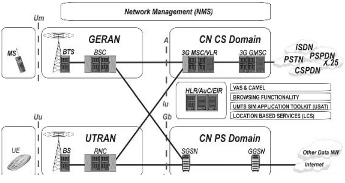
1.2.2 Structural Network Architecture
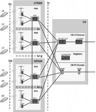
In this book we mainly present the issues from the network structural architecture perspective. This perspective is presented in Figure 1.3. In UMTS the GSM technology plays the remarkable role of the background and, actually, UMTS aims to reuse every-thing, which is reasonable. For example, some procedures used within the non-access stratum are, in principle, reused from GSM but naturally with required modifications. The 3G system terminal is called ‘‘UE’’ and it contains two separate parts, Mobile Equipment (ME) and the UMTS Service Identity Module (USIM).
The new subsystem controlling wideband radio access has different names, depending on the type of radio technology used. The general term is ‘‘Radio Access Network’’ (RAN). When we talk in particular about UMTS with WCDMA radio access, the name ‘‘UTRAN’’ or ‘‘UTRA’’ is used. The other type of RAN included in UMTS is GERAN. GERAN and its definitions are not part of 3GPP R99, though they are referred to as possible radio access alternatives, which may be utilised in the future. The specification of GERAN and its harmonisation with UTRAN is done in 3GPP R4 and 3GPP R5.
UTRAN is divided into Radio Network Subsystems (RNSs). One RNS consists of a set of radio elements and their corresponding controlling element. In UTRAN the radio element is Node B, referred to as Base Station (BS) in the rest of this book, and the controlling element is the Radio Network Controller (RNC). The RNSs are connected
to each other over the access network internal interface Iur. This structure and its advantages are explained in more detail in Chapter 5.
The other access network shown in Figure 1.3, GERAN, is not handled in detail in this book. Readers interested in GERAN should consult, e.g., Halonen et al. (2002). The term ‘‘Core Network’’ (CN) covers all the network elements needed for switch-ing and subscriber control. In early phases of UMTS, part of these elements were directly inherited from GSM and modified for UMTS purposes. Later on, when trans-port technology changes, the core network internal structure will also change in a remarkable way. CN covers the CS and PS domains defined in Figure 1.3. Configura-tion alternatives and elements of the UMTS core network are discussed in Chapter 6.
The part of Figure 1.3 called ‘‘Registers’’ is the same as the Home Network in the preceding 3G network conceptual model. This part of the network maintains static subscription and security information. Registers are discussed in more detail in Chapter 6.
The major open interfaces of UMTS are also presented in Figure 1.3. Between the UE and UTRAN the open interface is Uu, which in UMTS is physically realised with WCDMA technology. Some additional information about WCDMA on a general level is provided in Chapters 3 and 4. On the GERAN side the equivalent open interface is Um. The other major open interface is Iu located between UTRAN/GERAN and CN. The RNSs are separated from each other by an open interface Iur. Iur is a remark-able difference when compared with GSM; it brings completely new abilities for the system to utilise: so-called macro diversity as well as efficient radio resource manage-ment and mobility mechanisms. When the Iur interface is implemanage-mented in the network, the UE may attach to the network through several RNCs, each of which maintains a certain logical role during radio connection. These roles are Serving RNC (SRNC), Drifting RNC (DRNC) and Controlling RNC (CRNC). CRNC has overall control of the logical resources of its UTRAN access points, being mainly BSs. An SRNC is a role an RNC can play with respect to a specific connection between the UE and UTRAN. There is one SRNC for each UE that has a radio connection to UTRAN. The SRNC is in charge of the radio connection between the UE and the UTRAN. It also maintains the Iu interface to the CN, which is the main characteristic of the SRNC. A DRNC plays the logical role used when radio resources of the connection between the UTRAN and the UE need to use cell(s) controlled by another RNC rather than the SRNC itself. UTRAN-related issues in general are discussed in Chapter 5.
Access networks also have connections between themselves through an interface Iur-g. Iur-g is used for radio-resource-management-related information transfer. The difference between Iur and Iur-g is that Iur transfers both signalling and user data, while Iur-g only transfers signalling.
In addition to the CS and PS domains presented in Figure 1.3, the network may contain other domains. One example of these is the broadcast messaging domain, which is responsible for multicast messaging control. However, in this book we concentrate on the UMTS network as presented in Figure 1.4. As far as the various RANs are concerned, we concentrate on UTRAN and highlight some specific items related on UTRAN–GERAN co-existence and co-operation.
1.2.3 Resource Management Architecture
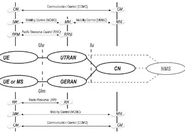
The network element-centric architecture described above results from functional decomposition and the split of responsibilities between major domains and, ultimately, between network elements. Figure 1.4 illustrates this split of major functionalities, which are:
. Communication Management (CM).
. Mobility Management (MM).
. Radio Resource Management (RRM).
CM covers all of the functions and procedures related to the management of user connections. CM is divided into several sub-areas, such as call handling for CS con-nections, session management for PS concon-nections, as well as handling of supplementary services and short-message services. MM covers all of the functions and procedures needed for mobility and security (e.g., connection security procedures and location update procedures). Most of the MM procedures occur within the CN and its elements, but in the 3G part of the MM functions are also performed in UTRAN for PS connections. The principles underlying CM and MM are discussed in Chapter 6.
RRM is a collection of algorithms UTRAN uses for management of radio resources. These algorithms handle, for instance, the power control for radio connections, different types of handovers, system load and admission control. RRM is an integral part of UTRAN and basic RRM is discussed more closely in Chapter 5. Some system-wide procedure examples about CM, MM and RRM functioning are given in Chapter 11.
Although these management tasks can be located within specific domains and network elements, they need to be supported by communication among the related domains and network elements. This communication is about gathering information and reporting about the status of remote entities as well as about giving commands to them in order to execute management decisions. Therefore, each of the management tasks is associated with a set of control duties such as:
. Communication Control (COMC).
. Mobility Control (MOBC).
. Radio Resource Control (RRC).
COMC maintains mechanisms like call control and packet session control. MOBC maintains mechanisms which cover, for example, execution control for location updates and security. Radio resources are completely handled between UTRAN and the UE. The control duty called ‘‘RRC’’ takes care of, for example, radio link establish-ment and maintenance between UTRAN and the UE. These collections of control duties are then further refined into a set of well-specified control protocols. For more detailed information about protocols see Chapter 10.
When compared with the traditional GSM system, it is apparent that this functional architecture has undergone some rethinking. The most visible change has to do with mobility management, where responsibility has been split between UTRAN and the CN. In addition, with regards to the RRM, the UMTS architecture follows more strictly the principle of making UTRAN alone responsible for all radio resource man-agement. This is underlined by the introduction of a generic and uniform control protocol for the Iu interface.
1.2.4 Bearer Architecture
As stated earlier in this chapter, the 3G system mainly acts as an infrastructure provid-ing facilities, adequate bandwidth and quality for end-users and their applications. This facility provision, bandwidth allocation and connection quality together is commonly called Quality of Service (QoS). If we think of an end-to-end service between users, the used service sets its requirements concerning QoS and this requirement must be met everywhere in the network. The various parts of the UMTS network contribute to fulfilling the QoS requirements of the services in different ways.
To model this, the end-to-end service requirements have been divided into three entities: the local bearer service, the UMTS bearer service and the external bearer service. The local bearer service contains mechanisms on how the end-user service is mapped between the terminal equipment and Mobile Termination (MT). MT is the part of the UE that terminates radio transmission to and from the network and adapts the terminal equipment capabilities to those of radio transmission. The UMTS bearer service in turn contains mechanisms to allocate QoS over the UMTS/3G network consisting of UTRAN and CN. Since the UMTS network attaches itself to external network(s), end-user QoS requirements must be handled towards the other networks too. This is taken care of by the external bearer service.
bearer service is quite constant in nature since the backbone bearer service providing the physical connections is also stable. Within UTRAN the radio access bearer experi-ences more changes as a function of time and movement of the UE, and this sets different challenges for QoS. This division also pursues the main architectural principle of the UMTS network (i.e., independence of the entire network infrastructure from radio access technology).
The structure presented in Figure 1.5 is a network architecture model from the bearer and QoS point of view. Since QoS is one of the most important issues in UMTS, QoS and bearer concepts are handled throughout this book.
The rest of the book uses these architectural approaches as cornerstones when exploring UMTS networks and their implementations.
2
Evolution from GSM to
UMTS Multi-access
Heikki Kaaranen
Evolution is one of the most common terms used in the context of Univeral Mobile Telecommunication System (UMTS). Generally, it is understood to mean technical evolution (i.e., how it has evolved and what kind of equipment and in which order it is brought to the existing network, if any). This is partly true, but, in order to under-stand the impact of evolution, a broader context needs to be examined. Evolution as a high-level context covers not only the technical evolution of network elements but also expansions to network architecture and services. When these three evolution types go hand in hand the smooth migration from 2G to 3G will be successful and generate revenue.
Technical evolution means the development path of how network elements will be implemented and with which technology. This is a very straightforward development and strictly follows general, common technology development trends. Because network elements together form a network, in theory the network will evolve accordingly. In this phase one should bear in mind that a network is only as strong as its weakest element and due to the open interfaces defined in the specifications many networks are combina-tions having equipment provided by many vendors. Technical evolution may proceed, however, at different rates in association with the different vendors’ equipment, and when adapting evolution-type changes between several vendors’ equipment the result may not be as good as expected.
Service evolution is not such a straightforward issue. It is based on demands gener-ated by end-users and these demands could be real or imagined; sometimes network operators and equipment manufacturers offer services way beyond subscriber expecta-tions. If end-users’ needs and operators’ service palettes do not match each other, difficulties with cellular business can be expected. These three dimensions of evolution are shown in Figure 2.1.
2.1 From Analogue to Digital
The main idea behind the Global System for Mobile Communication (GSM) speci-fication was to define several open interfaces, which determine the standardised components of the GSM system. Because of this interface openness, the operator maintaining the network may obtain different components of the network from differ-ent GSM network suppliers. Also, when an interface is open it defines strictly how system functions are proceeding at the interface and this in turn determines which functions are left to be implemented internally by the network elements on both sides of the interface.
As was experienced when operating analogue mobile networks, centralised intelli-gence generated a lot of load in the system, thus decreasing overall system performance. This is why the GSM specification in principle provided the means to distribute intelli-gence throughout the network. The above-mentioned open interfaces are defined in places where their implementation is both natural and technically reasonable.
From the GSM network point of view, this decentralised intelligence is implemented by dividing the whole network into four separate subsystems:
. Network Subsystem (NSS).
. Base Station Subsystem (BSS).
. Network Management Subsystem (NMS).
. Mobile Station (MS).
The actual network needed for call establishing is composed of the NSS, the BSS and the MS. The BSS is the part of the network responsible for radio path control. Every call is connected through the BSS. The NSS is the network part that takes care of call control functions. Every call is always connected by and through the NSS. The NMS is the operation and maintenance-related part of the network. It is also needed for the whole network control. The network operator observes and maintains the quality of the network and services through the NMS. The open interfaces in this concept are located between the MS and the BSS (Um interface) and between the BSS and the NSS (A interface). Um is actually very much like the Integrated Services Digital Network (ISDN) terminal interface, U; it implements very similar facilities to this system and also lower level signalling is adapted from narrowband ISDN. The small ‘‘m’’ after U in the name stands for ‘‘modified’’. The interface between the NMS and the NSS/BSS was
expected to be open, but its specifications were not ready in time and this is why every manufacturer implements NMS interfaces with their own proprietary methods.
The MS is a combination of a terminal’s equipment and a subscriber’s service identity module. The terminal equipment as such is called ‘‘Mobile Equipment’’ (ME), and the subscriber’s data is stored in a separate module called the Service Identity Module (SIM). Hence, MEþSIM¼MS. Please note that SIM officially stands for Subscriber Identity Module. We prefer the name ‘‘Service Identity Module’’, since it better describes the SIM functionality.
The Base Station Controller (BSC) is the central network element of the BSS and it controls the radio network. This means that the following functions are the BSC’s main responsibility areas: maintaining radio connections towards the MS and terrestrial connections towards the NSS. The Base Transceiver Station (BTS) is a network element maintaining the air interface (Um interface). It takes care of air interface signalling, ciphering and speech processing. In this context, speech processing means all the methods BTS performs in order to guarantee error-free connection between the MS and the BTS. The Transcoding and Rate Adaptation Unit (TRAU) is a BSS element that takes care of speech transcoding (i.e., capable of converting speech from one digital coding format to another and vice versa).
The Mobile Services Switching Centre (MSC) is the main element of the NSS from the call control point of view. MSC is responsible for call control, BSS control func-tions, interworking funcfunc-tions, charging, statistics and interface signalling towards BSS and interfacing with the external networks (PSTN/ISDN/packet data networks). Func-tionally, the MSC is split into two parts, though these parts could be in the same hardware. The serving MSC/VLR is the element maintaining BSS connections, mobil-ity management and interworking. The Gateway MSC (GMSC) is the element partici-pating in mobility management, communication management and connections to the other networks. The Home Location Register (HLR) is the place where all the sub-scriber information is stored permanently. The HLR also provides a known, fixed location for subscriber-specific routing information. The main functions of the HLR are subscriber data and service handling, statistics and mobility management. The Visitor Location Register (VLR) provides a local store for all the variables and
functions needed to handle calls to and from mobile subscribers in the area related to the VLR. Subscriber-related information remains in the VLR as long as the mobile subscriber visits the area. The main functions of the VLR are subscriber data and service handling and mobility management. The Authentication Centre (AuC) and Equipment Identity Register (EIR) are NSS network elements that take care of secur-ity-related issues. The AuC maintains subscriber-identsecur-ity-related security information together with the VLR. The EIR maintains mobile-equipment-identity-(hardware)-related security information together with the VLR.
When thinking of the services, the most remarkable difference between 1G and 2G is the presence of a data transfer possibility; basic GSM offers 9.6 kb/s symmetric data connection between the network and the terminal. The service palette of the basic GSM is directly adopted from Narrowband ISDN (N-ISDN) and then modified to be suitable for mobile network purposes. This idea is visible throughout the GSM implementation; for example, many message flows and interface-handling procedures are adapted copies of corresponding N-ISDN procedures.
2.2 From Digital to Reachability
The very natural step to develop the basic GSM was to add service nodes and service centres on top of the existing network infrastructure. The GSM specification defines some interfaces for this purpose, but the internal implementation of service centres and nodes is not the subject of this specification. The common name for these service centres and nodes is Value Added Service (VAS) platforms and this term adequately describes the main point of adding this equipment to the network.
A minimum VAS platform typically contains two pieces of equipment:
. The Short Message Service Centre (SMSC).
. The Voice Mail System (VMS).
Technically speaking, VAS platform equipment is relatively simple and meant to provide a certain type of service. It uses standard interfaces towards the GSM network and may or may not have external interfaces towards other network(s).
From the service evolution point of view, VAS is the very first step toward generating revenue with services and partially tailoring them. The great success story in this sense has been the SMS, which was originally planned to be a small add-in to the GSM system. Nowadays, it has become extremely popular among GSM subscribers.
IN as a technology has its roots in Public Switched Telephone Networks (PSTNs) and as such does not meet all mobile network requirements. Due to this, the original IN concept has been enhanced and introduced as CAMEL (Customised Applications for Mobile network Enhanced Logic). CAMEL eliminates the failings of IN, such as its lack of support for service mobility.
2.3 Jump to Packet World and Higher Speeds
At the outset, GSM subscribers have used the 9.6-kb/s circuit-switched (CS) symmetric ‘‘pipe’’ for data transfer. Due to the Internet and electronic messaging the pressures for mobile data transfer have increased a lot and this development was maybe under-estimated at the time when the GSM system was first specified. To ease this situation, a couple of enhancements have been introduced. First, channel coding is optimised. By doing this the effective bit rate has increased from 9.6 kb/s up to14 kb/s. Second, to put more data through the air interface, several traffic channels can be used instead of one. This arrangement is called ‘‘High Speed Circuit Switched Data’’ (HSCSD). In an optimal environment an HSCSD user may reach data transfer using 40–50-kb/s data rates. Technically, this solution is quite straightforward, but, unfortunately, it wastes resources and some end-users may not be happy with the pricing policy of this facility; the use of HSCSD very much depends on the price the operators set for its use. Another issue is the fact that most of the data traffic is asymmetric in nature; that is, typically a very low data rate is used from the terminal to the network direction (uplink) and higher data rates are used in the opposite direction (downlink).
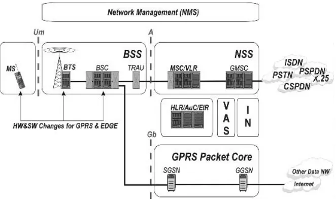
The CS symmetric Um interface is not the best possible access media for data connections. Furthermore, when we consider that the great majority of data traffic is packet-switched (PS) in nature, something more had to be done to ‘‘upgrade’’ the GSM network to make it more suitable for more effective data transfer. The way to do this is by using General Packet Radio Service (GPRS). GPRS requires two additional mobile-network-specific service nodes: Serving GPRS Support Node (SGSN) and Gateway GPRS Support Node (GGSN). By using these nodes the MS is able to form a PS
connection through the GSM network to an external packet data network (the Internet).
Figure 2.4 shows a simplified diagram of a GPRS network when it is implemented using basic GSM. Please note that a fully functioning GPRS network requires additional equipment, like firewalls for security reasons, DNS (Domain Name Server) for routing enquiries with the GPRS network, DHCP (Dynamic Host Config-uration Protocol) server for address allocation and so on. These pieces of equipment are not mobile-specific and they function exactly the same way as their ‘‘cousins’’ on the traditional Internet side.
GPRS has the potential to use asymmetric connections when required and in this way network resources are better utilised. GPRS is a step that brings Internet Protocol (IP) mobility and the Internet closer to the cellular subscriber, but is not a complete IP mobility solution. From the service point of view, GPRS starts a development path where increasingly traditional CS services are converted to be used over GPRS, because these services were originally more suitable for PS connections. One example of this is the Wireless Application Protocol (WAP), the potential of which is amply discovered when using GPRS. In addition, the greatest killer service in GSM (namely, SMS) behaves more optimally when transferring over a GPRS connection.
When PS connections are used, Quality of Service (QoS) becomes a very essential issue. In principle, GPRS supports the QoS concept, but in practice it does not. The reason here is that GPRS traffic is always second-priority traffic in the GSM network: it uses otherwise unused resources in the Um interface. Because the amount of unused resources is not exactly known in advance, no one can guarantee a certain bandwidth for GPRS in a continuous way and, thus, QoS cannot be guaranteed either. There are some ways to avoid this problem. The most cost-effective is to dedicate, for instance, one radio channel per cell for GPRS use only. By doing this, the operator is able to
guarantee at least some kind of GPRS capacity for the mobiles camped on this par-ticular cell. This method, however, does not provide any solid solution for QoS problems; it only eases the situation and improves the probability of gaining GPRS service in crowded, populated cells.
So far in this evolution chain, the GSM air interface has used traditional GSM modulation; the only other way to transfer data would be by means of either CS (HSCSD) or PS (GPRS) services. When using GPRS, the packet data transfer rate starts to be an issue, especially in the downlink direction. By applying a completely new air interface modulation technique, Octagonal Phase Shift Keying (8-PSK), where one air interface symbol carries a combination of three information bits, the bit rate in the air interface can be remarkably increased. When this is combined with very sophis-ticated channel-coding technique(s), one is able to achieve a data rate of 48 kb/s compared with conventional GSM which can carry 9.6 kb/s per channel and one information bit represents one symbol in the air interface. These technical enhance-ments are called ‘‘Enhanced Data Rates for Global/GSM Evolution’’ (EDGE).
The primary target with EDGE is to use it to enhance packet transfer data rates. This is why EDGE is often commercially introduced as E-GPRS (Enhanced GPRS). The implementation of EDGE as a technology requires some other changes in the network, especially on the transport mechanisms and transmission topology; the bit rates avail-able with the BSS for basic GSM purposes are not enough. This problem will especially come to the fore when the operator increases site density and introduces EDGE technology simultaneously. These two changes together may increase the average bit rate per end-user to amounts the transmission is unable to handle without any changes. When EDGE is implemented within the BSS its name changes to GERAN (GSM/ EDGE Radio Access Network). With the channel-coding methods that have been introduced and 8-PSK modulation, the GPRS terminal could in theory achieve a 384-kb/s data transfer rate. This requires that the GPRS terminal gets eight air interface time slots with the best channel-coding method available for its use. Thus, the data rate could be 848 kb/s¼384 kb/s. It should be noted that the EDGE-capable terminals in the market are not able to do this; commercial terminals are able to utilise four channels simultaneously at a maximum.
From a network evolution point of view, EDGE in general has its pros and cons. A good point is the data rate(s) achieved; these are getting close to UMTS urban coverage requirements. The disadvantage with EDGE is that the data rates offered are not neces-sarily available throughout the cell. If EDGE is to be offered with complete coverage, the amount of cells will increase dramatically. In other words, EDGE may be an expensive solution in some cases. The future of EDGE is nowadays seen as a complementary technology enabling better interworking with the Wideband Code Division Multiple Access (WCDMA)-based UTRAN and the GSM-based GERAN. These two access networks constitute the basic accesses defined for UMTS networks.
2.4 3GPP Release 99
3G introduced the new radio access method, WCDMA. WCDMA and its variants are global; hence, all 3G networks should be able to accept access by any 3G network
subscriber. In addition to its global nature, WCDMA has been thoroughly studied in the laboratory and it has been realised that it has better spectral efficiency than Time Division Multiple Access (TDMA) (under certain conditions) and it is more suitable for packet transfer than TDMA-based radio access. WCDMA and radio access equipment as such are not compatible with GSM equipment, and this is why, when adding the WCDMA to the network, one must add two new elements: the Radio Network Con-troller (RNC) and the Base Station (BS). The network part that contains these elements and maintains the WCDMA radio technology is called the ‘‘UMTS Terrestrial Radio Access Network’’ (UTRAN).
On the other hand, one of the key requirements for UMTS is GSM/UMTS inter-operability. One example of interoperability is inter-system handover, where the radio access changes from GERAN to UTRAN and vice versa during the transaction. This interoperability is taken care of by two arrangements. First, the GSM air interface is modified in such a way that it is able to broadcast system information about the WCDMA radio network in the downlink direction. Naturally, the WCDMA radio access network is able to broadcast system information about the surrounding GSM network in the downlink direction, too. Second, to minimise implementation costs, 3GPP specifications introduce possibilities to arrange interworking functionality with which the evolved 2G MSC/VLR becomes able to handle wideband radio access, UTRAN.
So far, the abilities provided by the IN platform have been enough from the service point of view. The concept of IN is directly adopted from PSTN/ISDN networks and, thus, it has some deficiencies as far as mobile use is concerned. The major problem with standard IN is that IN as such is not able to transfer service information between networks. In other words, if a subscriber uses IN-based services they work well but only within his or her home network. This situation can be handled by using CAMEL, as explained earlier. CAMEL is able to transfer service information between networks.
Later on, the role of CAMEL will increase a lot in 3G implementation; actually, almost every transaction performed through the 3G network will experience CAMEL involve-ment, at least to some extent.
Transmission connections within the WCDMA radio access network are imple-mented by using ATM (Asynchronous Transfer Mode) on top of a physical transmis-sion medium in a 3GPP R99 implementation. A pre-standardisation project FRAMES (1996–1998) discussed at great length whether to use ATM in the network or not. The final conclusion favoured using ATM for two reasons:
. ATM cell size and its payload are relatively small. The advantage here is that the need for information buffering decreases. When buffering is excessive, expected delays will easily increase and the static load in the buffering equipment will likewise increase. One should bear in mind that buffering and, thus, generated delays have a negative impact on the QoS requirements of real-time traffic.
. The other alternative, IP (especially its version IPv4), was also considered, but IPv4 has some serious drawbacks, being limited in its addressing space and missing QoS. On the other hand, ATM and its bit-rate classes match the QoS requirements very well. This leads to the conclusion that where ATM and IP are combined (for packet traffic), IP is used on top of ATM. This solution combines the good points of both protocols: IP qualifies the connections with the other networks and ATM takes care of connection quality and also routing. As a result of IPv4 drawbacks a compromise has been made. Certain elements of the network use fixed IPv4 types of addresses, while the real end-user traffic uses dynamically allocated IPv6 addresses, which are valid within the 3G network. To adapt the 3G network to other networks in this case, the 3G IP backbone network must contain an IPv4$IPv6 address conversion facility, because external networks may not necessarily support IPv6.
Core Network (CN) nodes have also evolved technically. CS domain elements are able to handle both 2G and 3G subscribers. This requires changes in MSC/VLR and HLR/ AC/EIR. For example, security mechanisms during connection set-up are different in 2G and 3G and now these CS domain elements must be able to handle both of them. The PS domain is actually an evolved GPRS system. Though the names of the elements here are the same as those in 2G, their functionality is not. The most remarkable changes concern the SGSN, whose functionality is very different from that in 2G. In 2G, the SGSN is mainly responsible for Mobility Management (MM) activities for a packet connection. In 3G, the MM entity is divided between the RNC and SGSN. This means that every cell change the subscriber does in UTRAN is not necessarily visible to the PS domain, but RNC handles these situations.
of services are moved/transferred/converted to the PS domain whenever reasonable and applicable.
The new services require new platforms for their implementation. Let us start with WAP: it had already been introduced in the context of GSM and GPRS. WAP had its own limitations and the content presented for end-users was not acceptable in all cases. Development on the terminal side has made it possible to use more sophisticated methods within the network. Instead of pure WAP, we could say that terminals utilise a browser functionality supported by the network. This browser functionality in turn implements XML definitions. End-users see this as a complete browsing experi-ence in colour display with formatted documents looking very similar to those gathered from the Internet via a normal, traditional desktop computer.
This browser functionality is a kind of cornerstone for the other services the 3G network offers to end-users. Another very attractive platform for services in this phase is the UMTS SIM Application Toolkit (USAT) which arranges the possibility of handling SIM cards over the air. In general, service personalisation will be a very interesting issue. One branch of services in this respect is that the delivered content depends on the location of the end-user. For this arrangement the 3G network contains a platform enabling the use of LCSs.
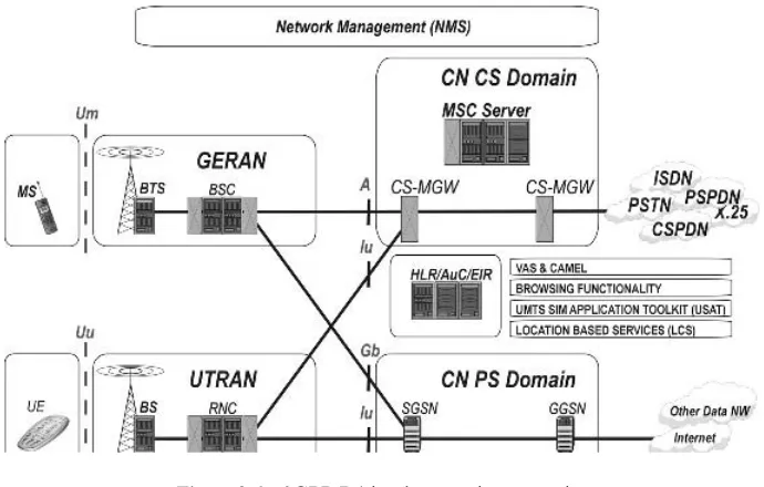
2.5 3GPP Release 4
In order to simplify matters, we could say that the 3GPP R99 implementation is a GSM-based, GSM-evolved mobile network containing two different access networks and delivering both CS and PS traffic with variable speeds.
According to published work on 3GPP evolution, 3GPP R4 contains some major items to be implemented. The most important from the network architecture point of view are the UTRA Frequency Division Duplex (FDD) repeater function, IP transport for CN protocols and bearer-independent CS CN.
WCDMA radio access provides excellent possibilities to extend coverage and ‘‘trans-fer’’ capacity within the radio coverage area, unlike GSM radio access. This is not, however, a simple issue as such, and the use of repeaters has its effect on, for instance, LCSs. 3GPP R4 offers an option to convert protocol stacks in such a way that the transport protocols become IP-based. The third mentioned item, bearer-independent CS CN brings scalability to the system. The traditional MSC contains both connection capacity and connection control capacity, but these two capacity types do not neces-sarily go hand in hand. 3GPP R4 defines the way to split these two capacity types into two different nodes.
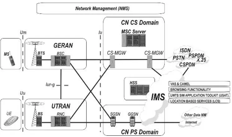
2.6 3GPP Release 5
After 3GPP R4 the aim was to implement the following major items:
. IP transport over the whole system from the BS up to the network border gateway.
. To introduce an IP Multimedia Subsystem (IMS) in order to start wide use of various multimedia services.
. To unify the open interface between the various access and core networks.
. To gain more capacity in the UTRAN air interface in the downlink direction.
The major items defined to be implemented in 3GPP R5 aim to simplify the network structure; making the transport protocol environment uniform enables more straight-forward solutions to be used than those used in R3 implementation. The first main item mentioned, IP transport throughout the whole network starting from the BS, has the aim of simplifying this transport network structure.
From the service point of view, the IMS will play a major role in R5 and further implementations. IMS is a separate system solution that is able to utilise various net-works itself; one of these is UMTS. With IMS, end-users will be able to use sophisti-cated multimedia and messaging services. IMS architecture is described in Chapter 6 and some related service aspects are discussed in Chapter 8.
From the end-user point of view, the UMTS aims to harmonise the network structure (i.e., the end-user is not necessarily aware through which access he or she is using the network and retrieving services). To make this experience as smooth as possible, the various access networks must be harmonised as much as possible. Within the network the ‘‘harmonisation point’’ is the Iu interface between the CN and the access networks.