DEVELOPMENT OF NON-DESTRUCTIVE MONITORING SYSTEM
FOR CHLORIDE PENETRATION INTO REINFORCED CONCRETE
STRUCTURES
Antoni
Lecturer, Civil Engineering Department, Petra Christian University Email: [email protected]
ABSTRACT
Reinforced concrete structures in marine environment are subjected to chloride penetration, which significantly degrades the structural performance due to the occurrence of corrosion in the steel reinforcement. The performance degradation of the structures would reduce the intended service life and caused higher maintenance and repair cost. Therefore, system to monitor chloride penetration into reinforced concrete before the starting corrosion of reinforcement is indispensable. An embedded probe system to detect chloride penetration into concrete was developed in Japan. This probe consists of a cementitious material body and some number of wires as sensors, which are set in the shallow ditches around the probe body. The system detect the chloride penetration by monitoring the initiation time of wire corrosion, it also has the advantages of continuous monitoring and early warning on the onset of corrosion in the reinforcement. However, the probe had not yet had high sensitivity for detecting critical chloride content in concrete. Therefore to increase its sensitivity, four types of improvements, namely partial coating of the wires, waterproofing on the probe body, filling the ditches with porous material and supplying small current on the wires were evaluated in this study. From the experimental result, it was observed that supplying small current and partial coating of the wires could improve the sensitivity of the probe significantly, while waterproofing treatment on the probe body and filling the ditches did not have significant contribution.
Keywords: non-destructive monitoring, embedded probe system, chloride penetration, marine structure, maintenance
INTRODUCTION
Corrosion of reinforcement in concrete structures can cause rapid performance deterioration of structures and thus reduce the service life significantly. To ensure that the concrete structure can be in service for the designed lifetime, a reliable monitoring system is required. With reliable system for monitoring durability of concrete, maintenance of the structure, including regular inspection and repair, could be reduced. When corrosion has already started on the reinforcement, restoration of the structure to its initial condition is difficult and sometimes impossible. Therefore, the development of monitoring system for concrete structures subjected to chloride penetration such as in the marine environment should be conducted. The aims are to monitor the ingress of chloride ions into the structure and to predict the time of onset of corrosion in reinforcement rather than to evaluate structure that is already in severe condition. Monitoring the durability of structure should be done as early as possible before visible deterioration appears on the structure.
Note: Discussion is expected before November, 1st 2006. The proper discussion will be published in “Dimensi Teknik Sipil” volume 9, number 1, March 2007.
A new probe system to detect the chloride pene-tration depth in concrete [1] has been developed in Japan. The probe consists of four very thin wires coiled in ditches at different depth around a cylinder shape body made of polymer cement mortar. The probe could detect the chloride penetration depth by measuring the electrical resistance of the thin wire. If the chloride level around the wire is higher than the threshold value, the wire that was protected by the alkalinity of the concrete will be depassivated by chloride ion and corrosion will start on the wire. After the wire corrodes, it will soon break because of its very small cross section and the resistance reading will be very high. Based on time and the depth of chloride penetration data from the probe, the corrosion initiation time on the steel reinfor-cement in concrete can be estimated.
PROBE DESCRIPTION
Mechanism of the Probe
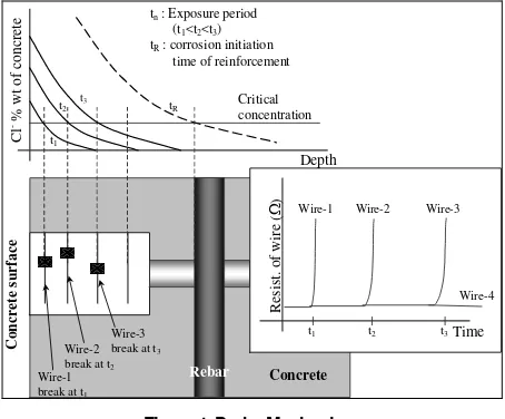
The probe is a cylindrical shape made of polymer cement mortar with stainless steel handle. Along the length of the probe, four very thin wires coiled in ditches of 1.5 mm depth at positions of 5 mm, 15 mm, 30 mm and 45 mm from the top of the probe. Diameter of the steel wires is 0.1 mm so that the resistance of the wires is very sensitive to corrosion. Each steel wire is connected separately by cable connection. The probe is expected to detect the chloride penetration depth by way of measuring the electrical resistance of the thin wire using Ohmmeter, as illustrated in Figure 1. The dimen-sions are shown in Figure 2. At initial condition where there is no corrosion on the wire, resistance of the wire is very low. If the chloride concentration around the wire is higher than the critical concen-tration to start corrosion, the wire is depassivated and corrosion starts at the wire. After the wire corrodes, the resistance measurement will gradually increase because the cross section area of the wire reduced. Since the original cross section is very small, the wire will break soon and the resistance measurement increases sharply. Time of the break of each wire is then recorded. Based on the time and the depth of the critical chloride concentration detected by the probe, the corrosion initiation time, tR, on the steel reinforcement in concrete can be estimated.
tR : corrosion initiation
time of reinforcement
Figure 1. Probe Mechanism.
Probe Shortcomings
The development of the probe had already overcomes several problems. Probe body was improved from PVC tube into dense polymer mortar because there was problem with the interfacial transition zone between the probe and the surrounding concrete.
Ditches in the probe were made to reduce the breaking of the wire during construction. Stainless steel handle was added to enable the measurement of potential of the wires.
(a) Schematic diagram of the probe system
(b) The chloride penetration probe
Figure 2. Probe Diagram.
From the previous report, Takewaka et al. [1] found that the probe has not yet had high sensitivity in detecting the critical amount of chloride to start the corrosion on reinforcement. The wire broke after a considerably high chloride concentration in the concrete around the wire. One possible cause was that the ditches were filled with mortar having a higher density than concrete. In this condition, the mortar surrounding the wire has lower diffusion coefficient than concrete, and chloride ions penetrate slower in the ditches. At the same time, the lack of oxygen in sound mortar reduced the corrosion rate at the wire significantly. In addition, some chloride ions were suspected to be absorbed by polymer cement. Therefore, actual chloride content in the ditches was smaller than the value measured in concrete consti-tuting the structure. Those possibilities resulted in the pseudo higher chloride threshold value. Thus, the probes should be improved further.
Improvements of the Probe
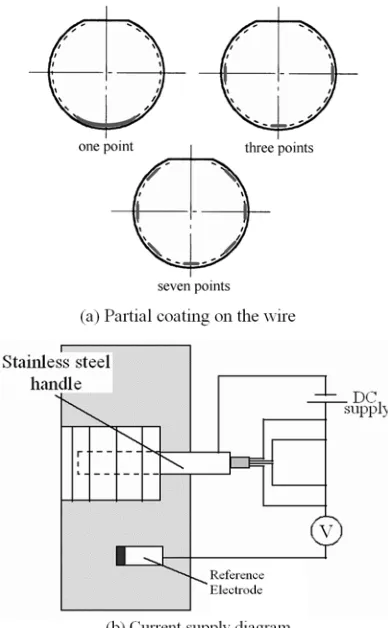
The first suggested improvement is partially coating the wires with vinyl chloride paint. These coating is intended to introduce crevice corrosion in the wire thus making the wire more sensitive to the chloride ions. Four types of coating, which are; no coating, one point, three points and seven points partial coating of the wire are evaluated (Figure 3(a)).
Figure 3. Improvements Condition Of The Probe.
As previously reported [1], small amount of chloride ions also penetrated to the probe’s body. The probe was suspected to absorb some of the chloride ion from concrete in ditch. Consequently, there was relatively lower chloride concentration at the point in the ditches and at the wire as compared with normal concrete portion. Therefore, the second improvement suggested is impregnating the surface of the probe with acrylic resin paint to seal the surface, considering that there would not be any bond deterioration between the probe and concrete.
The ditches around the probe body might be filled with dense mortar or cement paste when the surrounding concrete is cast. For avoiding this risk, the third improvement suggested is to fill the ditches with cement mortar with high water/cement ratio such as 0.9 or more before casting the probe into the specimen. With the high porosity of the ditches filling material, the chloride ions and oxygen are expected to penetrate easily into the ditches.
The fourth improvement suggested is to use small anodic current supply to wire which is also supposed to be able to improve the sensitivity of the probe. The passivation film on steel surface is reduced by supplying small anodic current to the wires hence the passive film will be easily destroyed by chloride ions and leading to corrosion of the wire at low chloride concentration. In this experiment the wires potential was increased to +600 mV against Ag/AgCl reference electrode. The method of application of the external current supply is shown in Figure 3(b).
EXPERIMENTAL PROCEDURE
Specimens
In accordance with the suggested improvements, three types of probe were developed and tested. The specifications of the probe are given in Table 1.
Table 1. Probe types
Type Description Coating of Wire Code No. of Probe
A Dimension: L1=50, L2=100, L3=150
• No water proofing • No top coating
No coating A 3
B Dimension: L1=60, L2=100, L3=160
• No water proofing • No top coating
No coating B 4
C Dimension: same as type B • Water proofing on probe body
with acrylic emulsion-type material
• Four types of coating of wire partially with vinyl chloride as shown in the right column • Top surface of probe is covered
with epoxy resin
No coating
1 point
3 points
7 points C0
C1
C3
C7 2
1
4
1
Total 15
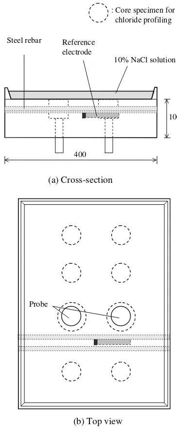
Fifteen probes were casted in eight specimens with size of 400 x 550 x 100 mm as shown in Table 2. Concrete specimen was made with w/c 0.7 to accelerate the penetration of chloride into concrete. Two probes were installed in each specimen as shown in Figure 4. Two steel bars and a reference electrode were installed in each concrete specimen in order to compare electrochemical properties of the probe with the steel bar. The steel bars were arranged in concrete with 3 cm and 2 cm of concrete cover. Reference electrode for measuring potential of wires in probe and steel bar were set near the steel bars. Six places for coring were also provided for the chloride measurement.
room, where the temperature and relative humidity is keep at 40 ºC and 70%, respectively.
Table 2. Specimen Type and Variation of Probe Condition
Checking mainly the effect of
waterproofing on the probe body and partial coating on the wire on the sensitivity of probe higher water to cement ratio types of coating arrangement and its influence
A-1 9 9
7 0.7
A-2 9 9*
8 0.7 A-3 9 -
Different ditch filling material with current supplied to the wire
* The ditches were filled with cement mortar having w/c ratio of 0.7
Resistance and potential of the steel wires were measured daily from the beginning of the exposure test. At the time when the wire broke, core of 50 mm diameter was taken to obtain the chloride concen-tration profile. Chloride concenconcen-tration was measured according to the Japan Concrete Institute code (JCI-SC5) [2]. When all wires broke, the probe was taken out by 75 mm coring and probe was inspected visually to see the corrosion on the wire.
RESULT AND DISCUSSION
Figure 5 shows the reading data of potential and resistance of wires in one of the probe. At the time when the wire broke, the resistance increased very sharply. On the other hand, the natural potential reading showed large fluctuations so that the starting of the corrosion could not be judged from this data.
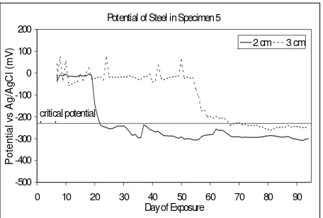
From the potential measurement of steel reinforce-ment (Figure 6), the initiation time of corrosion on the reinforcement can be seen by sharp decrease of natural potential. The critical potential value of -230 mV against saturated Ag/AgCl used corres-ponds to 90% probability of corrosion as stated in ASTM C 876 [3]. This value was used for deter-mining the corrosion initiation time of reinforcement.
100
400
10% NaCl solution Reference
electrode
(a) Cross-section Steel rebar
: Core specimen for chloride profiling
Probe
(b) Top view
Figure 4. Specimen Outline.
Resistance and pontential of Probe B2
0
Potential of Steel in Specimen 5
Figure 6. Potential of Steel Reinforcement.
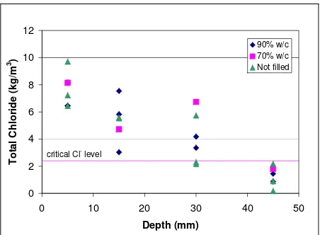
Figure 7 shows the chloride content in concrete at the depth of each wire just after the wire was broken. At the first and second wire positions, all wires broke after the chloride content reach two to three times of critical chloride level. This condition was considered to be due to lack of oxygen. The experimental setup which constantly providing salt solution on the concrete surface reduced the availa-bility of Oxygen. Therefore the wire breaks some time after the initiation of corrosion of upper wire. These conditions are not expected for concrete under real conditions where there is adequate Oxygen available.
Chloride Content at the Time of Wire Broken
0
Figure 7. Chloride Content at The Breaking Time of Wire
Some of the third wires and all of the fourth wires, however, broke when the chloride content at their position was less than the critical level. Conse-quently, the chloride content in concrete at each wire depth at the breaking time were largely scattered due to a problem in the experimental setup.
On the other hand, the result of previous experiment [1] under wet and dry condition (probe A1-5) showed that second, third and fourth wire were broken at about the same chloride content under current supply condition. Thus in the condition where there is enough oxygen in the concrete, the wire will be
broken at about the same chloride content as around the critical chloride content level.
It is found out from the experiment that the current supply is highly effective in increasing the probes sensitivity (Figure 8). All wires in the probes with current supply broke during the experiment period, while only about 40% wires broke in the probes without current supply. Potential of the wire shifted to positive direction by the anodic current can be effective to increase the sensitivity for its corrosion.
0%
with current supply without current supply
not broken wire broken
Figure 8. Percentage of Wire Broken
On the other hand, imposing anodic current can increase the chloride content locally due to electric migration of the chloride ions. This phenomenon will cause different chloride content between concrete near the probe surface and the surrounding concrete. Therefore, when the current is supplied, the imposed potential shift value should be considered. In this experiment, the potential was increased to +600 mV against Ag/AgCl reference electrode. Most of the wire at the 45 mm depth with current, broke at chloride content less than its critical value for corrosion initiation on reinforcement. This condition gives conservative estimation to the probe. Hence, for the actual condition when the probe will be installed in the structure it is more reasonable to use smaller value of potential shifting.
0
critical Cl- level
Figure 9. Effect of Partial Coating
At the end of the experiment period, the probe is taken out of the specimen and visual inspection was conducted. The corrosion on the wire was noted by the corrosion marks that show some brownish color of steel rust on the ditches surface (Figure 10). Outlet position of wire was the most likely place to start the corrosion on the wire without any coating. This condition can be explained as follow. At the outlet portions, wire was coming from the inside of the probe to the surface. Inside of the probe was denser than surrounding concrete so that wire was still in passive condition, while wire on the probe surface becomes active by the chloride penetration. Since such different condition between the wire portion in the probe body and at the probe surface caused macro cell corrosion, wire broke faster.
For the wire with partial coating, the corrosion mark found is mostly under the partial coating. Hence, this shows that partial coating can induce the corrosion more easily on the surface of the wire. Thus with more partial coating the sensitivity of the probe can be increased.
(a) (b) (a) (b)
Figure 10. Corrosion on (a) Near Outlet of Wire and (b) Under Partial Coating.
For checking the effect of waterproof coating on the probe body, probe type B and type C were compared. Figure 11 show the chloride content at the breaking time of wire in each concrete depth. Effect of water-proofing coating on bond property between concrete and probe does not clearly appear in this experiment.
Also, chloride content in concrete near probe was not much difference regardless of waterproofing coating.
0
Figure 11. Chloride Content for Type of Waterproofing on Probe Body
Figure 12 shows the effect of the filling condition in ditch on the predicted chloride content in concrete by the probe. From this figure, it seems that predicted chloride content was not much difference regardless of the ditch filling condition of the probe used. Therefore, there is no need to fill the ditch of the probe, in which the wire is coiled, with lower quality concrete or mortar.
0
critical Cl- level
Figure 12. Chloride Content for Different Filling Condition of Ditch
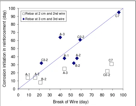
The correlation between corrosion initiation time of reinforcement estimated by the natural potential measurement with the breaking time of wires at the position corresponding to the cover depth of reinfor-cements is shown in Figure 13. Correlation of second wire to reinforcement with 2 cm of concrete cover shows that corrosion started on reinforcement before wire break. If this condition happen on the probe reading for actual structures, the estimation by using the probe would not be effective because the wire cannot detect the initiation of corrosion in reinforcement. The cause of this condition is that the concrete specimen was saturated with chloride Partial
coating Outlet
solution in this experiment. Therefore the wire being at the shallower position, took longer period for breaking of wire after corrosion initiation due to insufficient oxygen in the water saturated condition.
0 10 20 30 40 50 60 70 80 90 100
0 10 20 30 40 50 60 70 80 90 100
Break of Wire (day)
Cor
ros
ion init
iat
ion in reinf
o
rc
ement
(
day
)
Rebar at 2 cm and 2nd wire Rebar at 3 cm and 3rd wire
A-1
A-1
B-2
A-2 B-2 C3-2
A-3
C7 A-2
C0-2 C7
C0-2 A-3
Figure 13. Corelation of Corrosion Time in Reinforcement and Break of Wire.
On the other hand, good correlation can be made from relationship between time of third wire break and corrosion initiation time of reinforcement with 3 cm of concrete cover, though some variation still remain. From this condition, it seemed that the probe can detect the corrosion initiation time on the reinforcement in concrete structure under splash or atmospheric condition where oxygen sufficiently exists in concrete.
CONCLUSIONS
Increasing potential of wire by current supply can significantly increase the sensitivity of the probe to detect critical chloride content in concrete. Increasing potential up to +600 mV against Ag/AgCl reference electrode was found to be effective. However more study should be done for variations of imposed potential.
Partial coating on the wire surface can introduce the occurrence of corrosion more easily. Thus, the sensitivity of the probe can be increased with increasing the number of partial coating points. Using both combinations, it is expected that the sensitivity of the probe to chloride concentration can be improved.
The use of waterproofing on the probe body will not affect the bond property between the probe and concrete but the sensitivity increment is not significant.
Filling the ditches with low quality concrete or mortar does not increase the sensitivity of the probe.
Therefore, it is not necessary to adopt these two conditions.
Probe system can effectively predict the lifetime of structure, especially in the splash zone or upper part of the marine structure where both chloride and oxygen easily penetrate into concrete, the usage of probe can be very effective to monitor the structure.
REFERENCES
1. Takewaka, K., Nguyen, X.H., Leelalerkiat, V., Yamamoto, S., A Non-Destructive And Quantitative Monitoring System For Pene-tration Of Chloride Into Concrete Structure, EASEC-8 Proceeding, Singapore, 2001,paper no.1390.
2. JCI (1989), Standard for Testing Method on Corrosion and Corrosion Protection of Con-crete Structure (1984.4), Japan ConCon-crete Institute. (in Japanese)