Proceeding Forum in Research, Science, and Technology (FIRST) 2016
DESIGN OF INDUCTION HEATING FOR COAL LIQUEFACTION
Nova Rachmadona
1), Yohandri Bow
2), Arizal Aswan
3)1,2,3)
Chemical Engineering Department, Politeknik Negeri Sriwijaya, Jl. Srijaya Negara Bukit Besar, Palembang, South Sumatera Indonesia 30139
Email : [email protected]
Abstract.Energy conservation is one method from the government to improve the use of energy in Indonesia. High frequency inverter design which is used as an induction heating device appropriate conservation measures. This design is chosen because it can be applied to any process that requires heating by using a material with high conductivity. In this study, the heater is used to liquefy lignite. Induction heating requires high-frequency inverter module. Using the AC voltage single phase rectified to a bridge rectifier, inverter will convert AC voltage into DC voltage, 12V– 22V, which electrical quantities with a frequency can be set. Voltage is derived using a step-down transformer that is used little power. Once out of the step-down transformer is passed a winding inducer which induce object to be heated. The measurement results show inverter module that is made has a frequency of 40 kHz and can generate heat the sample up to 401 degrees Celsius within 5 minutes with the inverter efficiency of 82.8%.
Keywords: inverter, frequency, induction heating, liquefaction.
I. INTRODUCTION
Energy of principal necessity and energy consumption is increase each year, while the reserves are limited. Energy consumption enhancement is in line with the development of industrial sector in the production process.
Therefore, there are efforts to improve the energy usage. One of efforts is diversification energy conservation. Energy conservation is a systematic, planned and integrated effort in order to conserve energy resources in the country and improve the efficiency of utilization [1]. The implementation of energy conservation covers all aspects of energy management.
Efficiency is one step in the implementation of energy conservation. Energy efficiency is the energy or the power to do something in taking advantage of time, effort and expense. Therefore, it is not wasted or energy efficiency is considered among the most effective ways of reducing carbon-dioxide emissions[2]. In view of the general public sometimes defined energy efficiency as well as energy savings.
One method for energy savings is using high frequency inverter as induction heating [3-6].Induction heating is converting electrical energy into heat energy and the generated heat is strongly influenced by the frequency [7]. This frequency is generated by a single phase inverter circuit and this circuit also functions as a voltage resource.
The cost for the utilization is low because the power source is a direct current (DC) which carries low electrical energy consumption [5]. The high-frequency inverter based on power electronics are closely related to frequency, voltage, current inputs, and the object to be heated. Each of these factors has an influence on the heat generated. By using a microcontroller and power electronics, the value of these factors can be changed so that it allows for testing thermal characteristics [6].
In addition, this technology does not cause exhaust emissions or dust as it is occurred in fossil energy, does not require a large space in the process of utilization, can produce not only high temperatures in a fast time but alsoheat spread deeper and create an environmental advantages. [4] According to the US Department of Energy, Efficiency of energy transfer for induction heating is 84% while the electric heater is not induced by 71%, so there is a saving of around 13% in the use of electrical energy [8].
Based on the conditions, the researchers will design a high frequency inverter that can be used as an induction heater. These heaters can be applied to a wide range of processes, both for melting or smelting. In this study, the inverter is used to liquefy coal that requires a high temperature during the process because so far the heating process is conventional performed and the conventional heating process requires start-up time is longer and requires considerable energy. Therefore, to solve the problem,using high-frequency inverteris the best method that can generate a relatively quick warm-up time compared to conventional heating process.
The purpose of this research is to produce the high frequency inverter that can be applied to coal liquefaction [9-10], to determine the effect of the rise in temperature voltage inverter system, and to get an induction heating that has higher performance efficiency than the heating element.
II. MATERIALS AND METHODS A. Materials
Coal was obtained from Geo-services, Mineral and Coal Laboratories (Palembang, Indonesia).
B. Functional Design Approach
coils. A power supply section consisted of a transformer ankle, which decreased the voltage from 220V into 60V and diode functioned to rectify the electric current output from the transformer [10]. Transformer ankle was a transformer that had only 1 lane secondary winding. The transformer functioned to prevent transformer overheating due to excessive electric current. Additionally, fan was paired near the transformer.
R1and R2 were resistors with each of resistance values,
470Ω andpower, 2W. The amount of resistor determined the
speed of metal oxide semi-conductor (MOSFET) on. The value of resistance should be small so the speed of MOSFET was high enough and could be eliminated by the diode when the other MOSFET in the on position.
Diode D1and D2were used to clear the MOSFET gate. Using a diode with a low forward voltage drop was a method to make gate completely empty and MOSFET could be fully off when the other one on. Schottky diodes could be chosen because it has a low drop voltage (12V) and high speed. Allowable voltage on the diode should be enough to anticipate the voltage enhancement at the resonant circuit.
The coilsfunctioned to drain electric current back around the workpiece to generate eddy currents. [10] Power supply and alternating current were placed in a casing made of wood, to prevent them induced by alternating current. The reactor was designed to function as a place to heat up the steam coal that could be produced from the reactor condensed in the condenser [11].
Fig. 1 Design of Reactor
C. Structural Design Approach
Induction heating was designed with several components that were assembled into one, which might be divided over the power supply, the alternating current and working coils. A power supply section consisted of a single transformer and 4 pieces each with a capacity diode 40A. Single transformer was a transformer that had only 1 lane secondary winding. The transformer used had a maximum capacity of 10A, which was limited by the fuse 8A. Additionally, fan was paired near the transformer. R1 and R2 were resistors with resistance values respectively 470Ω and 10kΩ . Schottky
Diode was chosen because it had a low drop voltage (12V) and high speed. The coil worked as a 5 inch diameter, consisting of five winding copper wire with a diameter of 3 mm. In the reactor design was made of metal pipe where the reactor was 3.5 inch in diameter and 15 cm high.
Condenser design was using an aluminium pipe with a diameter of 5 inches with a height of 20 cm where the flow of cooling water was used copper wire with a diameter of 3 mm with a length of 1 m. At the bottom, there was a container frame asan outlet for cooling water both to the coil and into the condenser. Inside the container there were 2 pieces aquarium pump.
D. Procedures Equipment Design
Simulations were performed using PSIM software 9.0 to determine whether the series had been appropriate or not. If the circuit had been appropriate, the device was assembled, if not continuously tried the circuit simulation until it was suitable and appropriated for the desired frequency.
Coupling process for electronic tool was used solder and tin as a liaison of electronic components. Testing the chain and using an iron bar that was inserted into the loop was done. Testing was declared successful when the bar would be hot in a short time.
After coupling was followed by the manufacture of the reactor and the condenser, the size of the reactor was adjusted to the circle of heating coils. Liaison between the reactor and the condenser was used copper pipe. In the circuit as well as the condenser was connected with a pump that functioned to drain the cooling water. cooling water was flew in copper coil which cooled the copper during the process so that it could last a long while in the condenser to condensate steam in the reactor to produce the yield.
E. Experimental Procedure
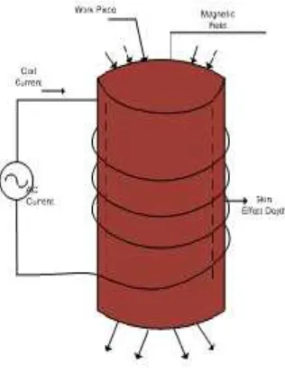
Power supplywas turned on and the conductor wire would be electrified which would create around it would form lines of magnetic force. The reactor received the influence of the magnetic lines of force within the reactor eddy current would flow. Each reactor was made of metal which usually had no electrical resistance, and the current flowing in the metal would produce the power that came out as heat and the ongoing process called induction heating.
Temperature in the reactor was measured and recorded every 30 seconds for 5 minutes. The time was required for the first drops of distilled noted. The experiments were performed with various sizes of coal and mixture ratio between coal and solvent.
Proceeding Forum in Research, Science, and Technology (FIRST) 2016 III. RESULTS AND DISCUSSION
A. Design of Inverter by Using PSIM 9.0
The components are simulated by software, PSIM 9.0, to know the main cycle and components which generate the real frequency for liquefaction. The method is by input the all data, which have been calculated before, into software. Then, the result shows it can be run or not. It is figured by Fig 2.
Fig. 2 Design of Component by Software
B. Heat Speed Variation Voltage Testing
The heat speed testing isperformed for 5 minutes with lapse of time every 30 seconds. To view the rise of temperature reached, thermometer gun is used. In addition to know the speed of heating, it alsomeasures current value reducing when the inverter works.
Fig. 3Temperature Rise and Decline Graph Flowat Resonant Steady
From Fig. 3, it can be seen that the temperature increases with increasing heating time at frequency of 38.46 kHz. Heating speed would decrease if the temperature increased because the higher the temperature, the more energy wasted heat into the surrounding environment where the temperature is lower and the temperature rise occurred very quickly while the time required to reach a temperature of 400oC is 5 minutes and the temperature is in accordance with the temperature required for the liquefaction process. The
temperature rise also causes a decrease in current due to the heating process because this process requires eddy currents. Eddy currents have a dominant role in the process of induction heating. Heat generated in the material is very dependent on the magnitude of the eddy currents induced by the coil inducers. When winding fed by alternating current, it will give rise to a magnetic field around the wires. The magnitude of the magnetic field varies in accordance with the current flowing in the coil. If there is a conductive material around the magnetic field changing, the conductive material will flow currents called eddy currents. Therefore, a decrease in the flow of increasingly sluggish due to material induced from the magnetic field is reduced so that the state is getting a constant flow.
From Oscilloscope, Vpp measurement is measured 23.4Vso:
Vm = (2)
=
.
= 11.7 V
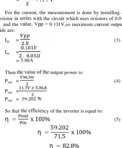
For the current, the measurement is done by installing a resistor in series with the circuit which uses resistors of 0.01
Ω and the value, Vpp = 0.101V,so maximum current output
side are:
Then the value of the output power is:
Pout = . (4)
Pout = . .
Pout = 59.202 W
So that the efficiency of the inverter is equal to:
η
=
x 100%
(5)η
=
59.202
71.5
x 100%
η
= 82.8%
Inverter efficiency reaches 82.8%. This proves that the series of induction heating system is more efficient in power usage compared to the heating element.
distillation process, the experiments were performed with voltage variation so it gets the time requirement for liquefaction in induction heating.
In Fig. 4 that the large power usage is in the input voltage 22 V, it is directly proportional to the time that is used in the distillation process because the use of high input voltage will increase the currents. Heat generated in the material is very dependent on the magnitude of the eddy currents induced by the coil. When winding fed by alternating current, it will give rise to a magnetic field around the wires. The magnitude of the magnetic field varies in accordance with the current flowing in the coil.
Fig. 4Effect of Time Input Voltage to Length of Coal Liquefaction Time
Fig. 4 shows that the size of the coal used also affects the length of time distillation in which the smaller the particle size of the coal, the less time is needed. This has proved that the particle size also affects the melting process.
E. Effect of Input Power to Thermal Efficiency of Liquefaction Process
For the use of induction heating energy required for the liquefaction process can be seen from the performance efficiency of induction heating device to liquefy coal.
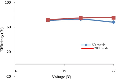
Fig. 5Effect of Input Power to Thermal Efficiency of Liquefaction Process
Fig. 5 is known that distillation shortest time is at a voltage of 22 V. However, the efficiency of the appliance inverter are gradually declining and higher energy
consumption than voltage of 20 V. It can be concluded tha the use of voltage 22 V is not efficient in terms of energy utilization. The use of high energy can cause overheating in the equipment continously because some components have certain specifications for its use. Even with the excessive power usage, it can lead to decreasing the quality of the resulting components replaced with new components.
The size of the coal particles also affects the efficiency of the induction heating where the smaller the particle size, the lower thermal efficiency is occurred and also the use of energy tend to be smaller because the lower distillation time causes the lower energy fed.
IV. CONCLUSIONS
Based on the test performance of high frequency inverter and the results of calculations, simulations and experiments, it can be concluded that:
1. For the coal liquefaction process, it can be used a voltage on the 18V, 20V, and 22V because the temperature for liquefaction process can be reached at those voltages.
2. The current and voltage is very influential on the system temperature rise because voltage is the main thing that led a process of working on the coils. The greater input voltage, the higher temperature rise per second will increase.
3. The efficiency of the induction heating at a frequency of 38.46 kHz is 82.8%. It proves that the series of induction heating system is more efficientthan the heating element in power usage.
4. In the process of coal liquefaction, it is evident that both the particle size and input power variations can affect the time of distillation where the smaller the particle size, the faster the time of disbursement and also the greater the power input, the faster the time of disbursement would be occurred.
5. Co-liquefaction of biomass could moderate the reaction conditions of coal liquefaction due to the synergistic effects between coal and biomass, and improve the quality and yields of liquid products. However, so far the mechanism behind the synergistic effects of co-liquefaction and induction heating is yet to be clarified, so further research should be conducted.
ACKNOWLEDGEMENT
This work achieved an award from Governor of South Sumatera through Centre of Research and Innovation South Sumatera as the best innovation categories of students held in 20th Commemoration of the Resurrection of National Technology South Sumatra 2015.
REFERENCES
[1] Sugiyono, A., Pengembangan Energi untuk Mendukung Pembangunan Berkelanjutan, Outlook Energi Indonesia 2015, Sugiyono, A., Anindhita, Boedoyo, M.S., Adiarso, Center for Energy Resources Development Technology, pp 23, 2015. [2] Yusuf, A. A.,Energy Efficiency Priority for Indonesia: A General
Equiibrium Analysis. Working Paper in Economics and Development Studies, No. 201506, 2015.
Proceeding Forum in Research, Science, and Technology (FIRST) 2016 Thesis, Electrical Engineering., Diponegoro University,
Semarang-Indonesia, 2013.
[4] Internalis, B., Pengaruh Variasi Tegangan DC Chopper Dan Variasi Frekuensi Inverter Pada Pengaturan Kecepatan Motor Induksi 3 Fasa 1 Hp Berbasis Mikrokontroller, Undergraduate Thesis, Electrical Engineering., Diponegoro University, Semarang-Indonesia, 2007.
[5] Noviansyah, R.,Pemanas Induksi (Induction Heating) Kapasitas 200 Watt. Undergraduate Thesis, Mechanical Engineering., Gunadarma University, Depok-Indonesia, 2011.
[6] Zhulkarnaen, Y.,Perancangan dan Pembuatan Pemanas Induksi dengan Metode Pancake Coil Berbass Mikrokontrollet Atmega 8535.Undergraduate Thesis, Electrical Engineering., Brawijaya University, Malang-Indonesia, 2013.
[7] Vivek, R.G., Satish, V.B., Atul, B.B, Induction Furnace, International Journal of Engineering and Technology, Vol. 3(4), pp. 277-284, 2011.
[8] Greg, S., David, Z., Improving Range-Top Efficiency with Specialized Vessels,Appliance Magazine, 2009.
[9] Dewi Andrianny, R.,Studi Pemanfaatan Batubara di Pabrik Pupuk, Thesis, Chemical Engineering, Bandung Institute of Technology, Bandung- Indonesia, 2007.
[10] Hidayat, Pengaruh Peringkat dan Kondisi Operasi Pada Proses Pencairan Batubara, Thesis, Chemistry, University of Indonesia, Jakarta-Indonesia, 1995.
[11] Anam, C.M.,Elektronika.Pasuruan Modul Alat Ukur Elektronika Yogyakarta: Universitas Negeri Yogyakarta, 2008.
[12] Rencono, A.,Desain dan Analisa Induksi. Undergraduate Thesis, Electrical Engineering, Universitas Katolik Semarang, Semarang-Indonesia 2000.