Implementation of Private Cloud for Optimization of
Computer Resources at University
Agustinus Noertjahyana, Henry Novianus Palit, Daniel Kuntani
Petra Christian UniversityAbstract—The development of computer technology and applications are very rapid, causing the needs of computer use in the organization has increased. The performance of personal computers has increased rapidly, but it cannot be utilized properly. Therefore, personal computers can be used together to perform parallel processing, so that data processing time can be shortened. Private cloud, as an alternative solution to provide cloud services to organizations that are on the same network. The service provided is Infrastructure as a Service (IaaS), where users can request certain types of services and use certain operating systems.
Universities have many computers in the laboratory that have considerable resources if they are able to optimize the use of each computer as a processing resource. Supported by high specification on each computer, it is suitable for private cloud implementation. Using the Openstack framework can produce a good enough performance to perform parallel data processing. The test results show that the parallel processing performance works as expected.
Index Terms—Computer Resources; IaaS; Openstack; Private Cloud.
I. INTRODUCTION
The development of applications is very fast along with the development of computing technology. Distributed applications and parallel processing require large computer resources. Cloud computing is a system that combines several computers into a unified system with the availability of more processor and memory [1]. Although the technology is up-to-date, according to IBM Research Report, CPU usage at various Data Centers is very low, ranging from 7% to 25% with an average of 18%. This means that computers in various Data Centers use more processor specifications to perform activities on the Data Center [2].
At the university, computers with the latest specifications are also not utilized optimally, so that with the cloud computing computer resources can be used to perform parallel processing. The openstack framework as an alternative to cloud computing is an excellent tool to test computer performance simultaneously[3-4].
II. THEORY
Cloud computing is a computational model for enabling scattered, convenient, and on-demand computer network access to share configurable computer resources, such as networks, servers, storage, applications, and services [5]. Cloud computing has 3 service models offered: Software as a Service (SaaS), Platform as a Service (PaaS) and Infrastructure as a
Service (IaaS) [4]. Computers on the same network can perform parallel processing using the openstack framework and Openstack provides Infrastructure as a Service (IaaS).
A. Openstack
OpenStack is a cloud system software platform that acts as a middleware. Middleware is a software layer that provides programming abstraction, and combines the various layers below, such as networks, hardware, operating systems and programming languages [6]. This means that OpenStack is a service that provides hardware capabilities and is part of Infrastructure as a Service (IaaS). OpenStack consists of various components that communicate with each other to provide services to users. These components include:
• Network Time Service provides the date and time for each node that is in the system.
• Databases are used to store data during operations because most OpenStack services require databases to store information.
• Message Queue Server (RabbitMQ) is a messaging broker, an intermediary for messaging. RabbitMQ provides a common platform for sending and receiving messages and securing messages until messages are received.
• Identity service provides authentication and gives the client node a token that allows access to OpenStack cloud services.
• Image service provides discovery, registration and delivery services for disk images and server images.
• Scheduler (compute management) functions to select computing resources, ie computers that act as compute nodes.
• Dashboard is a Web application used for OpenStack cloud system administration.
• API services are used by applications running in OpenStack systems. The API services provided also include APIs belonging to other nodes.
• Hypervisor or Virtual Machine Manager is a software, firmware, or hardware that works to create and run Virtual Machine. For Hypervisors, libvirt is a driver for Hypervisor that allows live migration from one node to another node.
• Nova-compute, which is the main part that runs the operation.
• Cinder Block Storage stores all data used by the virtual machine.
B. Identity Service / Keystone
Keystone provides identity service and access policy services to all components in OpenStack. Keystone implements REST-based APIs as identity.
OpenStack components. Authentication verifies that the actual request is coming from the correct source, there are two authentication methods that are username / password based and Token based. Autorization verifies user permissions to the requested service [7].
The components inside the Keystone consist of tenant, service endpoint, regoin, user and role [7]. Here is an explanation of these components:
• Endpoints.
Each service on OpenStack has a URL (host) and on a dedicated port. The URL and port are called Endpoints.
• Regions.
Region defines the physical location within a data center. In a cloud setting, most services are generally scattered throughout the data center or server, also called the region.
• User.
An account authenticated by Keystone. • Services.
All services connected with keystone are keystone service. For example, glance (image service) is a keystone service.
• Role
Roles restrict user access within the cloud infrastructure. • Tenant.
Tenant is a project with all the services, endpoints and users on the tenant.
C. Openstack System
Registered users can access the IaaS feature provided by the cloud system through the user interface of the website. Users can request a virtual machine by selecting a flavor (specs such as CPU, RAM and disk capacity) and image (operating system) [8].
The controller node, where the website is located, will perform the scheduling, which selects the IP address for the virtual machine and compute nodes that meet the criteria according to the capacity requested by the cloud user. At this stage various Openstack services will work together to check user rights over hardware, image, network and storage before running an instance (virtual machine).
A number of instaces that run will be on a virtual network that is formed on the host where the virtual machine is operating. It is as if the number of instances is a set of nodes in a cluster.
The user already has a virtual environmet created from a collection of virtual machines. Each virtual network formed is connected to the network bridge on the host's physical interface so that it can connect to the network outside the virtual network, in this case the private network belonging to Petra Christian University.
The user as the instance owner must access the instance through the console interface provided on the website only at the first instance of the instance. This step is the stage where the cloud users do the initial setup of the operating system and also the installation of other programs if desired.
Users can enable connections on certain ports according to the security group, a type of OpenStack's firewall. Furthermore, it can be done direct connection to the instance without going through the web interface. The openstack design scheme can be seen in Fig. 1.
Figure 1: Openstack Schema
III. SYSTEMDESIGN
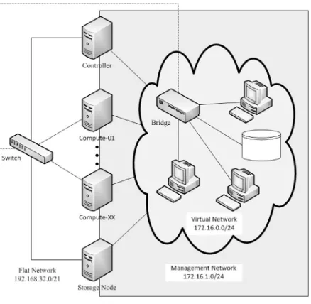
OpenStack requires 2 networks: Management Network and Public Network. Management Network are used to provide a line of communication systems and cloud administration. Public Network provides access from cloud users, in case of private cloud, this network is a private network (or also called Flat Network). Flat network use the available arrangement which is a private network (192.168.32.0/248). The network will then be shared, 172.16.1.0/24 into a management network and partly for use on a virtual machine that will operate on a cloud system, is 172.16.0.0/24. The network design can be seen in Fig. 2.
A. Basic Environment
Basic environment needed to build openstack system are nodes with operating system Ubuntu Server 14.04 LTS. For each node, the hardware specification is as follows:
Processor: Intel Core i5-3340 @ 3.1 GHz (2 cores / 4 threads)
RAM: 16 GB Disk: 250 GB
Connection: 1 interface 100Mbps Ethernet
In addition, the installation process of the basic components required by Openstack. The basic components are as follows:
OpenStack Packages
For OpenStack packages installation, Juno cloud repository should be added to the source-list of Advanced Package Tool (APT). APT on each node must update and dist upgrade.
MariaDB
The Database Management System (DBMS) is mandatory because it is used to store information for every service running on OpenStack. The DBMS installation is performed on the node controller. MariaDB is an open source DBMS that is suggested in making the cloud using OpenStack since the Juno version.
MariaBD has many performance optimizations compared to MySQL in performing simple query execution. So MariaDB is able to handle more SQL commands in units of time.
RabbitMQ
RabbitMQ is a message broker who receives and continues messages. The RabbitMQ installation is performed on the node controller. In RabbitMQ, all components of OpenStack (services) will act as guest. The settings on RabbitMQ are not changed except the guest password.
Network Time Protocol (NTP)
NTP installation is done to all nodes residing on the private cloud system. However, the role of the node controller differs from that of the other nodes. NTP on the node controller has a function to provide timing to all other nodes in a private cloud system. For that, the NTP setting on the node controller, must use itself as the time provider and answer the NTP request from another node.
On nodes other than the controller, NTP will be directed to adjust their timing settings to the time provided by the node controller. So that all nodes in the private cloud system have the same time settings as the node controller.
B. Application Framework
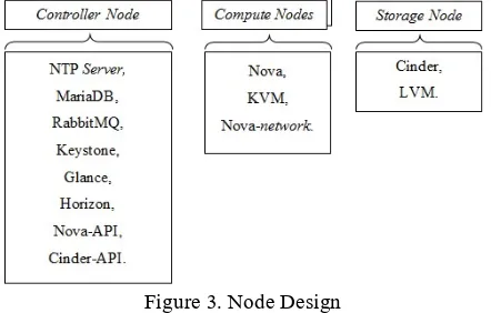
The framework used is Juno's OpenStack version, a number of components that operate on OpenStack-based cloud systems. These components are separated into several nodes: a controller node with multiple compute nodes, and additional nodes such as storage nodes and network nodes. Node design can be seen in Fig. 3.
C. Controller Node
Controller Node is the computer in charge of managing the operation of the system as a whole. At this node there are the following components:
• Keystone
Keystone as Identity service must register service, admin and user who will use system.
• Compute Management
Compute management is a part of the nova compute service located on the node controller.
• Nova-network settings
The settings are performed on the node controller to get to know the legacy network provided by the compute node.
• Horizon
Horizon installation is done after all the main components have been running properly. Horizon is a dashboard used by users to access services provided by private cloud.
• Cinder API
Cinder as additional installation needed to provide service volume. This service is required by virtual machine to have storage media so that each data in accordance with the wishes of the user.
Installation done on the node controller is just the API of the cinder. Cinder API is used to divide the work on the use of volume service by all virtual machines on the system.
D. Compute Node
The compute node acts as the host for the virtual machine run by the user. For that, the compute node has a hypervisor, KVM, a most widely used and tested virtual machine manager (VMM) for the OpenStack system.
Another arrangement is made to form the nova-network that assigns the IP address to the virtual machine. The Nova API is located on the node controller so that network and work settings and distribution are not performed on the compute node.
E. Storage Node
Storage node is an additional node that is added as a storage medium used as virtual hard drive in virtual machine. Before the arrangement takes place a partition is required as a storage medium. The partition provided on the each computer is 250 GB, so the partition created is 200 GB by providing the remaining 50 GB for the Ubuntu system including root and swap.
The partition can be shared to the user and serves as a removable disk between virtual machines. For its use, the user needs to take some capacity to be a virtual disk. Then, the virtual disk can be attached to a VM and the user can access the virtual disk via NFS using a VM in the form of a physical disk.
Figure 3. Node Design
F. Virtual Machine Image
OpenStack as a decent operating system operating as a virtual machine. The selected images are:
Windows Server 2012 R2 Standard Evaluation Edition
Ubuntu Server 14.04
Debian (CLI) Windows XP 32-bit
Flavor is a template provided as a virtual machine specification. Flavor includes CPU, RAM and disk capacity. The list of the Flavor can be seen in table 1.
Table 1 List of Flavor
Flavor CPU Core VCPU Capacity (GB) Memory Disc Capacity (GB) Tiny 1 1 20 Small 1 2 40 Medium 2 4 60 Large 2 8 100 XLarge 4 14 200
IV. SYSTEMIMPLEMENTATION
A. Installation Process
Implementation of openstack Framework using 8 computers, namely: Cont1 as Controller Node, Sto1 as Storage Node. While Cm1, Cm2, Cm3, Cm4, Cm5 and Cm6 as Compute Node.
Each node includes a Node Controller using 2 connected networks, for settings and virtual interfaces. IP Address on the computer using the network configuration in Fig. 2. The IP address of the main interface is 192.168.38.xxx where xxx is the computer number. The IP address of the virtual interface is 172.16.1.xxx where xxx is the computer number.
For each node to recognize another node on the network is to log the IP address into the IP Address-Hostname pair list in the /etc/hosts file for each node.
The openstack installation process is done by following the steps provided by Openstack document. The Openstack installation manual contains a complete guide to the installation process [8].
B. Error Handling
In the implementation process there are problems as follows: * Nova Service
Nova Service has a dependency on the database (MariaDB). Problems found during Controller Node. Nova services (including nova-cert, nova-consoleauth, nova-scheduler and nova-conductor) are first run by the operating system before the database service is successfully executed. This causes Nova Services to fail and stop. The solution is to change the script at the initializing service by the operating system (Ubuntu 14.04). The location of the script is in the / etc / init / directory. The addition of the script will make Nova Service wait for the database before running the service.
* Cinder Error
Cinder or block storage divides a partition into small parts according to the user and gives it to the user. When the request is submitted to the cinder, the application cannot share the partition and return the error message.
This happens because the app does not have permissions to
change hardware settings. The solution is to provide cinder access as super user, by editing the / etc / sudoers file on Storage Node (Sto1) at the end of the file with the command:
Cinder ALL = (ALL) NOPASSWD: ALL (1)
C. Add Image File
To get the image, done by downloading the image from the official website or create the image from the installer. Images downloaded through the official website are Windows Server 2012 R2 Standard Evaluation Edition, Ubuntu 14.04 and Debian 8.0 (CLI), while the Windows XP image is created through an ISO Installer.
All images need to be uploaded to the glance to be run by openstack. Here's an example of a command used to upload a Windows XP image.
$ glance image-create --name "Windows XP" \ –-file wxp.qcow2 \
--disk-format qcow2 --container-format bare \ --is-public True --progress
D. System Result
Testing based on the base cache functionality that occurs on the system, Nodes that have cache for base image, need spawning time between 5 to 10 seconds, while for nodes that do not have cache takes time depending on the size of the image used. The time required to run each image without using the cache can be seen in table 2.
Table 2
Image, Size and Spawning Time without Cache
Image name Size (MB) Spawning Time
Cirros-0.3.3-x86_64 13 10 – 15 detik Ubuntu 14.04 Trusty 251 30 – 40 detik Debbian Jessie 64-bit 447 40 – 60 detik Windows XP 1.699 2 – 3 menit Windows Server 2012 16.780 25 – 30 menit
The placement of the instance (Virtual Machine) can form several host sharing scenarios. The test will use only 2 scenarios:
An instance in a host
Multiple instances in a host
Using these two scenarios, testing is done by calculating the time required by the system to run an instance until the operating system runs. Test results can be seen in Table 3.
Table 3
Test Result from Multiple Instances
Image Scenario 1 (s) InstancesScenario 2Time (s)
Debian Jessie 31
4 60
Windows XP 30 90
Ubuntu 14.04 180 240
Windows Server 2012 720 2 660
Based on table 3 shows that if the host runs multiple instances takes longer time.
Testing is done by making an instance closest to a node using
the largest flavor (m1.xlarge).
Testing aims to determine the ability achieved by an instance compared with the actual host. Therefore, testing is performed against a host and an instance.Test results on CPU, memory and I / O can be seen in Table 4-6.
Table 4
Sysbench Result between Instance and Host (CPU)
Parameter Instance Host
Maximum prime number
checked in CPU test 20000 20000 Test execution summary
Total time 7.4611s 6.8509s Total number of events 10000 10000 Total time taken by event
execution 29.8209 27.3939 Per-request statistics:
Events (avg/stddev) 2500.0000/37.93 2500.0000/15.78 Execution time (avg/stddev) 7.4552/0.00 6.8485/0.00
Table 5
Sysbench Result between Instance and Host (Memory)
Parameter Instance Host Fisik
Operations performed 1 (149.26 ops/sec) 1 (154.75 ops/sec) Transferred 32.00 MB
(4776.38 MB/sec) (4952.08 MB/sec) 32.00 MB Test execution summary
Total time 0.0067s 0.0065s Total number of events 1 1 Total time taken by event
execution 0.0063 0.0062 Per-request statistics:
Events (avg/stddev) 1.0000/0.00 1.0000/0.00 Execution time (avg/stddev) 0.0063/0.00 0.0062/0.00
Table 6
Sysbench Result between Instance and Host (I/O)
Parameter Instance Host Fisik
Operations
performed: Read Write Others
Total time 60.0076s 60.0032s Total number of events 13600 18800 Total time taken by event
execution 0.0063 0.1187 Per-request statistics
Events (avg/stddev) 13600.0000/0.00 18800.0000/0.00 Execution time (avg/stddev) 0.1235/0.00 0.1187/0.00
The second benchmark uses HPCC. HPCC (High Performance Computer Challenge) is a benchmark software used to measure the performance of a distributed system (cluster). HPCC is another name for LINPACK Benchmark, a benchmark software provided by top500.org that provides high-performance computer related statistics.
Before running the benchmark, the host used should form a cluster. The first step is to make SSH authentication without a password from one host to all other hosts in the cluster. After the cluster is formed, proceed with the HPCC instalasa process and perform the test.
Testing is done by comparing the benchmark results using physical instances and hosts. The results of the measurement and performance comparison between instances and physical hosts generated using HPCC Benchmark can be seen in Table 7.
Based on the data in Table 7, it shows that the performance of an instance / virtual machine is slightly lower against the physical host. On the other hand, each benchmark result using multi-nodes produces a low performance compared to a host. This means that the use of muti-nodes through the network does not improve application performance.
The third benchmark uses Blender. Blender is software for rendering animations and can be used as a cluster render farm. Blender is loose-couple software, which means breaking the animation into several frames separated by its rendering process on many computers.
Testing is done by using animation consisting of 50 frames. The number of nodes used is 5 pieces of virtual machine instance. The configuration uses 1 master node and 4 slave nodes. The results of the tests performed can be seen in Table 8.
Table 8 Test Result using Blender
No. Test Node Slave Rendering Time (s)
V. CONCLUSION
Implementation of private cloud by utilizing computer resources has satisfactory results in several ways: Good computer network capable of supporting the performance of private cloud though still takes a long time in the delivery of image. Image caching feature can help in solving this problem
Instance on the system is able to achieve performance close to physical host performance, so the CPU capacity can be used optimally.
The disadvantages of this private cloud are on network capabilities that do not support applications such as HPCC. These tight-coupled apps have dramatically reduced performance when run on more than a computer / node.
ACKNOWLEDGMENT
This research project is sponsored by the Directorate General of Higher Education Indonesia on the scheme "Penelitian Produk Terapan” in 2017, and many thanks to Center of Research, Petra Christian University, Surabaya, Indonesia for
great support.
REFERENCES
[1] J. Glanz. The Cloud Factories: Power, Pollution and the Internet. URI=http://www.nytimes.com/2012/09/23/technology/data-centers-was-te-vast-amounts-of-energy-belying-industry-image.html. 2012. [2] R. Birke, L. Y. Chen, and E. Smirni. Data Centers in the Wild: A Large
Performance Study. URI= http://domino.research.ibm.com/lib-rary/cyberdig. 2012.
[3] Li Z, Li H, X. Wang, and Li K. A generic cloud platform for engineering optimization based on OpenStack. Adv Eng Softw [Internet]. 2014. pp:42–57.
[4] O. Litvinski, and A. Gherbi. Experimental Evaluation of OpenStack Compute Scheduler. Procedia Comput Sci [Internet]. 2013. pp:16–23. [5] P. Mell, and T. Grance. The NIST Definition of Cloud Computing.
Gaithersburg, United State: National Institute of Standards and Technology. 2011.
[6] G. Coulouris, J. Dollimore, Kindberg, and G. Blair. Distributed Systems Concepts and Design. Boston: Addison-Wesley. 2012.
[7] A. Jha, D. Johnson, K. Murari, M. Raju, V. Cherian, and Y. Girikumar. OpenStack Beginner's Guide (for Ubuntu - Precise). 2012.