HORIZONTAL POSITION OPTIMAL SOLUTION DETERMINATION FOR THE
SATELLITE LASER RANGING SLOPE MODEL
Yu Wanga,* Yu Aib Yu Hub RenLi Wangb
aXi’an Surveying and Mapping Institute, No. 1 Middle Yanta Road , Xi’an, China, 710054[email protected] b Aerors Inc., Xi’an, No. 1 Middle Yanta Road, Xi’an, China, 710054- [email protected],
[email protected],[email protected]
Commission I, WG I/2
KEY WORDS: Laser ranging; Fresnel diffraction; Slope model; Echo signal; Horizontal position
ABSTRACT:
According to the Gaussian-fit laser echo model and the terrain slope model, the regular mean value theorem and the asymptotic principle of the median point of the double integral mean value theorem are used to derive the optimal solution for the horizontal position of a single-mode laser echo. Through simulation experiments, the horizontal position results of the echo signal peak from various terrain slopes are analyzed. When ignoring the effect of the atmosphere and the surface roughness of the target, considering the geometric position of the Gaussian single-mode echo signal peak to be the center of the laser spot is highly accurate. However, as the accuracy significantly decreases when the slope is greater than 26°, making the range of the peak value of the single-mode echo data (for a slope of less than 26°) to be the range of the geometrical center of the laser spot can obtain a higher degree of accuracy.
* Corresponding author
1. INTRODUCTION
Laser ranging technology is a new technology which has been widely used in earth sciences and planetary exploration. Satellite laser ranging technology involves the use of a laser altimeter installed on the satellite, to measure the distance from the satellite to the ground, and obtain the ground elevation directly or help an optical camera to achieve high-precision 3D positioning (Wang, 2014(a); Wang, 2014(b); Wang, 2013). As a result of the flight height and the influence of laser energy, the laser beam diameter is generally greater than 30 m on the ground, so it is impossible to obtain a dense point cloud. The spot size also determines the upper limit of the plane resolution. Therefore, satellite-borne laser altimeters are mainly used in the measurement of high-precision 3D control points, or ground control point network adjustment.
For both three-dimensional control point measurement and distance measurement, the core problem is the measurement of the two-dimensional coordinates of a certain number of points, and the corresponding range from the satellite to the ground. However, the use of laser echo data to calculate the ground point location is a typical ill-posed problem that involves solving the three-dimensional position coordinates through two-dimensional known conditions.
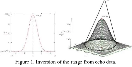
As shown in Figure 1, during the actual measurement of the laser altimeter, the received echo signal is an extension and superposition of the echo signal in the time domain and the spatial domain of each object in the laser spot. Processing of the echo signal can only determine the height distribution of the laser spot area and cannot obtain the actual range value of each point in the laser footprint (Li, 2007). Most scholars regard the range value of the peak of the echo data as the range of the geometric center of the laser spot. However, this assumption is not rigorous, because the laser spot shows a Gaussian distribution in the space and time domains (Garner, 1982), and the energy is a collection of multiple energies within the target’s
reflection. If there are many reflectors on the ground, and the height difference of the ground object is greater than the resolution of the laser ranging, the echo signal will show a multi-peak shape, so using the peak point as the spot center location will result in a large error. Even if the ground is flat, the reflection energy peak will be derived from multiple spots within the scope, so we cannot simply regard the range of the peak as the range of the geometric center. In this paper, a theoretical model for the laser echo signal is first analyzed. Simulation experiments then prove that when ignoring the effect of the surface roughness of the target, for a slope of less than 26°, regarding the range of the echo data energy peak P (x, y) as the range of the geometric center G (x, y) is highly accurate; however, when the slope is greater than 26°, this assumption will result in a large error.
Figure 1. Inversion of the range from echo data.
2. THEORETICAL ANALYSIS OF THE LASER RANGING OPTIMAL SOLUTION
The laser echo is the superposition of several individual echo waves caused by the target’s reflection from different distances. Because of the complexity of the actual object, the echo is multi-peaked, and it can be decomposed into a single-peak shape for analysis. According to Fresnel diffraction theory (Li,2007) and Gardner’s theory (Gardner 1982) , the laser The International Archives of the Photogrammetry, Remote Sensing and Spatial Information Sciences, Volume XLI-B1, 2016
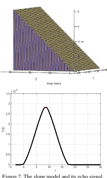
transmission equation shown in Eqs. (1)–(4) can be derived. The common diffuse-reflection target-object model can be abstracted into three categories: sloped terrain, ladder-shaped terrain, and vegetation terrain. The echo of the ladder-shaped terrain and vegetation terrain is multi-peaked, and the sloped terrain is single-peak. When ignoring the influence of surface roughness, the model can be expressed as shown in Eq. (5). The definition of the symbols used in Eqs. (1)–(5) is shown in Table 1.
T Transmittance of the optical system
t
E Energy of the emitted pulse t RMS pulse width
z
Track height of the range finder
Nadir angle (beam scanning angle) R Length of the beam axis (ρ) Reflectivity of target in the spot) , (x1 y1
ρ Target cross-section coordinate vector Laser wavelength
c
Velocity of light in a vacuum h(ρ) Target surface profile in the scan coordinate system
Beam divergence at the center of the spot where energy is2
Table 1. Definition of the symbols used in Eqs. (1)–(5).
Slope terrain
Figure 2. The slope model and its echo signal.
The power of an echo signal is similar to a Gaussian function of an independent variable. The function is continuous and has a
Because time t has no connection with the integral variable, in the double integral ofPr( )t, tcan be regarded as a constant,
we regard g(x1,y1,t) and f x y t( , , )1 1 as binary functions of
independent variables x1andy1.
Therefore:
1) At any given momentt , f x(1,y t1, )andg(x1,y1,t)can be regarded as continuous functions of and ;
2) As g(x1,y1,t)is similar to a Gaussian function, (z)and (ρ, φ) are constant and greater than zero. We define
1 1
the regular mean value theorem (Fan, 1978), and conclusion can be obtained by the theorem directly:
Conclusion 1: at least one point exists, making:
(10) The International Archives of the Photogrammetry, Remote Sensing and Spatial Information Sciences, Volume XLI-B1, 2016
This means that at least one point exists that can make the first
order derivative equation of the laser radar equation based on
the slope model ( Eq. (10)) is established.
By further analysis of Eq. (10), because g(x1,y1,t)0 ,
from the theorem about the regular mean value point (Cai, 2005;
Guo, 2011), it can be found that the regular mean value point
) ,
(xy satisfies the following formulas:
(12)
(13)
By combining the expressions of (Eq. (7)) and Eq. (10), we can obtain:
(14) Furthermore, when from (Eq. (12)) and Eq. (13),
get .
process, under the assumption that a certain amount of error is permitted, the position of the peak value of the single-peak laser echo can be considered to be the geometric center of the spot.
3 SIMULATION EXPERIMENTS
The parameters of the simulation experiments were set according to the Geoscience Laser Altimeter System (GLAS) system parameters (Brenner, 2000), which are shown in the
Table 2. Parameter settings of the simulation experiments
The plane coordinate range on the ground was set asDxy{(x,y)0x30,0y30}, (approximately the size of the laser spot), and the spot area footprint was divided into a 60 × 60 grid.
Experiment 1: Using the echo signal, the corresponding range of the peak of the echo wave can be obtained. When the ground model and satellite coordinates are known, the distance from the satellite to the ground grid location can be calculated. The two sets of distance values are matched in the range of a certain error, and the corresponding multiple solutions(x,y) can be
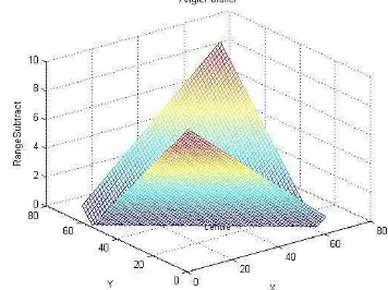
obtained. Figure 3 shows the echo signal peak positioning error distribution when the vertical and horizontal slopes are 16°. The Z-axis is the error between the range obtained by the echo signal peak value and the distance from the satellite to the grid point. Taking 60 points as the optimal solution for the minimum error, the optimal solution of the echo peak value is distributed in a straight line at the center of the spot.
Figure 3. Peak position error distribution when the slope model is 16°. solution of the echo peak value for the different slopes. Figure 4(a) is the result when S// and Schange at the same time, with
a change interval of 1°. Figure 4(b) is the result when the S//
direction change interval is 2° and the Sdirection is fixed at
15°. It can be seen from Figure 4 that in each kind of slope, the distribution of the optimal solution is a straight line, and all the straight lines cross through the center of the laser spot.
(a): Change in both the horizontal and vertical directions The International Archives of the Photogrammetry, Remote Sensing and Spatial Information Sciences, Volume XLI-B1, 2016
(b): Change in the horizontal direction, with the vertical direction fixed
Figure 4. Optimal distribution of the echo signal peak value in different slope gradients.
Experiment 2: In order to prove that the best position of the laser echo signal peak value for the slope model is the geometrical center of the spot, 24 points around the center of the spot were randomly selected to compare with the two norms, and the results are shown in Table 3 and Table 4.
6 m 12 m 15 m 18 m 24 m
6 m 2.8384 2.2912 1.9720 3.7781 2.4052
12 m 4.9189 2.8083 1.6447 0.9793 1.8476
15 m 3.3780 1.2242 0.2040 0.9775 3.1296
18 m 2.4091 0.6622 1.2812 2.1108 4.2254
24 m 2.0051 3.1309 4.1701 4.9763 7.0076
Table 3. Horizontal and vertical change at the same time, 25 points of the two norms.
6 m 12 m 15 m 18 m 24 m
6 m 8.7006 6.0453 4.4982 3.3952 0.8043
12 m 5.8037 3.1502 1.6101 0.5489 2.1946
15 m 4.1154 1.4690 0.2560 1.2314 3.8745
18 m 2.9116 0.3366 1.3278 2.4262 5.0791
24 m 0.2880 2.6673 4.2125 5.3182 7.9743 Table 4. Horizontal change, with the vertical direction fixed, 25
points of the two norms
As can be seen from the tables, the further away from the center point, the higher the accuracy, and the larger the value of the two norms, the worse the position accuracy. Therefore, setting the range of the slope echo peak P (x, y) to be the range of the spot center can obtain a higher precision than setting it to any other value.
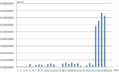
Experiment 3: In order to compare the influence of different slope gradients on the location error of the spot center, the location error of the spot center of a slope was compared, where the slope gradient was changed from 0-30° at 1° intervals (see Figure 5). It can be seen from Figure 5 that when the slope changes from 0° to 26°, the range error of the spot center
increases slightly, but the variation is very small and the overall error is less than 2 cm. However, the error increases to 10 cm above 27°.
Figure 5. The spot center location error for different slopes.
Therefore, when selecting the range of the laser echo signal peak as the approximate range of the center of the spot, to ensure a high accuracy, it is best to select a terrain slope gradient of less than 26°, in both the parallel and vertical directions to the flight track.
4 CONCLUSION
In this paper, according to the satellite laser altimeter echo signals and the slope model, through theoretical analysis, it is shown that by reducing the spot size, the energy center gradually approaches the geometric center of the spot. Using the GLAS satellite parameters, the simulation results for slope data varying from 0-30° show that the optimal solutions of the horizontal position corresponding to the echo signal peak all cross through the spot center. This indicates that the position of the center point of the spot of the slope model can be used as the position of the echo peak, and a higher precision can be ensured with a slope of less than 26°. In the actual measurement process, the range of the center point of a single-peak echo wave (for a slope of less than 26°) can be used as the range of the geometric center of the spot G (x, y).
In this paper, the effect of terrain roughness was not considered, and the simulation experiments were carried out for slopes of less than 30°. Our future research will consider the influence of terrain roughness and terrain slopes above 30°.
ACKNOWLEDGEMENTS
This work was supported by the National Natural Science Foundation of China (project 41571443).
REFERENCES
Brenner, A., Zwally, H.J., Bentley, C., et al,2000. Derivation of range and range distributions from laser pulse waveform analysis for surface elevations, roughness, slope, and vegetation heights. Geoscience Laser Altimeter System (GLAS) Algorithm Theoretical Basis Document.
Cai, W., 2005. Asymptotic Quality on Point of Mean Value for Double Integrals. Journal of Shanghai University of Electric Power, (1), pp. 90–92.
Fan, Y., 1978. Advanced Mathematics. High Education Press, Beijing, China.
Gardner, C.S., 1982. Target signatures for laser altimeters: an analysis. Applied Optics, 21(3), pp. 448–453.
Y
Y
X
X
Gonzalez, J.H., Bachmann, M., Scheiber, R. and Krieger, D., β010. Definition of ICESAT Selection Criteria for Their Use as Height References for TanDEM-X. IEEE Transactions On Geoscience and Remote Sensing, 48(6), pp. 2750–2757.
Guo, H. and Tan, Y., 2011. Discussion on asymptotic properties of point of mean value of double integral. Journal of Chongqing Technology and Business University (Nat. Sci. Ed.), 28(2), pp. 154–160.
James, B.A., Sun, X.L. and Robert, S.A., 2000. Mars orbiter laser altimeter receiver model and performance analysis. Applied Optics, 39(15), pp. 2450–2451.
Kumar, A. and Trivedi, P., 2012. CO-Kriging Approach for Cartosat-1 Height Product with ICESAT/GLAS Data for Digital Elevation Surface Generation. Journal of the Indian Society of Remote Sensing, 40(1), pp. 11–17.
Li, S., Zhou, H., et al., 2007. Theoretical model for return signal of laser altimeter. Optics and Precision Engineering, 5(1), pp. 33–39.
Wang, J., Wang, R., et al., 2013. Application of laser distance measurement data in linear array satellite photogrammetry. Science of Surveying and Mapping, 38(2), pp. 15–16.
Wang, R. and Wang, J., 2014(a). Technology of bundle adjustment using two-line-array CCD satellite image combined laser ranging data. Journal of Geomatics Science and Technology, 31(1), pp. 1–4.
Wang, R., 2014(b). Chinese photogrammetry satellite without ground control points (2)-technical thinking of 1:10 000 scale data-transferring photogrammetry satellite. Spacecraft Recovery & Remote Sensing, 35(2), pp. 1–5.
Wu, N., Sun, S. and Li, X., 2014. Space-borne Laser Full-waveform Ranging Technology. Spacecraft Recovery & Remote Sensing, 6(35), pp. 68–75.
Zhao, N. and Hu, Y., 2008. Synthesizing algorithm for laser remote sensing imaging multi-signal. Infrared and Laser Engineering, 37(4), pp. 667–682.