CALIBRATION PROCEDURES IN MID FORMAT CAMERA SETUPS
Frantisek Pivnicka1, Gerhard Kemper2, Stefan Geissler3
TopoL Software s.r.o, Prague, Czech Republic / GGS GmbH, Speyer, Germany / ppm GmbH, Penzberg, Germany,
KEY WORDS: Sensors, Photogrammetry, LIDAR, Camera, GPS/INS, Platforms, Sensor,
ABSTRACT:
A growing number of mid-format cameras are used for aerial surveying projects. To achieve a reliable and geometrically precise result also in the photogrammetric workflow, awareness on the sensitive parts is important. The use of direct referencing systems (GPS/IMU), the mounting on a stabilizing camera platform and the specific values of the mid format camera make a professional setup with various calibration and misalignment operations necessary. An important part is to have a proper camera calibration. Using aerial images over a well designed test field with 3D structures and/or different flight altitudes enable the determination of calibration values in Bingo software. It will be demonstrated how such a calibration can be performed. The direct referencing device must be mounted in a solid and reliable way to the camera. Beside the mechanical work especially in mounting the camera beside the IMU, 2 lever arms have to be measured in mm accuracy. Important are the lever arms from the GPS Antenna to the IMU’s calibrated centre and also the lever arm from the IMU centre to the Camera projection centre. In fact, the measurement with a total station is not a difficult task but the definition of the right centres and the need for using rotation matrices can cause serious accuracy problems. The benefit of small and medium format cameras is that also smaller aircrafts can be used. Like that, a gyro bases stabilized platform is recommended. This causes, that the IMU must be mounted beside the camera on the stabilizer. The advantage is, that the IMU can be used to control the platform, the problematic thing is, that the IMU to GPS antenna lever arm is floating. In fact we have to deal with an additional data stream, the values of the movement of the stabiliser to correct the floating lever arm distances. If the post-processing of the GPS-IMU data by taking the floating levers into account, delivers an expected result, the lever arms between IMU and camera can be applied. However, there is a misalignment (bore side angle) that must be evaluated by photogrammetric process using advanced tools e.g. in Bingo. Once, all these parameters have been determined, the system is capable for projects without or with only a few ground control points. But which effect has the photogrammetric process when directly applying the achieved direct orientation values compared with an AT based on a proper tiepoint matching? The paper aims to show the steps to be done by potential users and gives a kind of quality estimation about the importance and quality influence of the various calibration and adjustment steps.
1. BASIC INSTALLATION NEEDS
Using direct referencing devices with precise a GPS-IMU system, a proper mounting is needed. Basically, a stabile mechanic mounting of the IMU device related to the sensor (camera) is important. Being aware that depending on the quality of the IMU, the measurement of the rotation angles happens in some milidegree accuracy. The mechanic mounting has to meet this requirement. In most cases, thermal influence can cause such instability. Often, aluminium materials with a minimum thickness of 10 mm are used as carrier. The problem can be that different temperature on the top and bottom side can deform the plate and the angles between IMU and sensor change. That’s why in some cases sandwich constructions are used to prevent such deformations. As long as the deformation is less than the resolution of the IMU, we do not have to take too much care about that. However, depending on the sensor and the IMU, both devices produce heat that might be isolated from the basic plate, otherwise we again might cause the temperature deformation problem.
There are different sandwich- or ceramic plates in use, however, the installation is in most cases done individually.
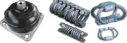
Important is also to prevent the system against vibration and resonances. The sensor might produce unsharp images; in our case the IMU could get problems by accelerations that are unexpected. Vibrations typically create accelerations in the 3 axis and depending on the IMU, this can lead to dramatic
inaccuracies. Especially small and light aircrafts or helicopters are faced with such problems. Being aware that an IMU should measure properly the rotations and not accelerations, there can appear serious inaccuracies. Good to know the vibration spectrum of the aircraft, like that the right bumpers can be installed.
Figure 1: Various shock mounts and bumpers to reduce vibrations
2. LEVERARM GPS-IMU
A very important parameter for the overall system accuracy is the GPS-IMU lever arm. Still, many users do not determine the lever arm with the required care and accuracy. Actually you need to measure the distance and orientation between the phase centre of the GPS Antenna and the orientation centre of the IMU. The phase centre of the GPS Antenna typically is documented in the technical specs? It is defined as relative International Archives of the Photogrammetry, Remote Sensing and Spatial Information Sciences, Volume XXXIX-B1, 2012
XXII ISPRS Congress, 25 August – 01 September 2012, Melbourne, Australia
value related to some feature e.g. the antenna mounting screw holes. These values are typically in mm accuracy. If there is an offset of the phase centre, we have to keep care of the antenna orientation to apply this offset correctly while mounting on the aircraft.
A similar definition of the IMU centre is given in their calibration protocol. These parameters are typically related to the mounting plate or some corners of the IMU body. Also, it is very important to mount the IMU according to the IMU defined body frame axis (X, Y and Z).
Typically the determination of the lever arms is done using a total station. As a final result, the antenna offset has to be within the orientation system (body frame) of the IMU. This in fact is not always done properly. Normally the misalignment calibration can fix that but in case of using a stabilized platform it is very important to do that properly. In our case, we measure the 4 screw points on the IMU and the 4 screw holes of the GPS antenna, feed the results into a excel calculation, add the offset of the IMU and GPS antenna centre and get as a result the offset of the antenna phase centre related to the IMU measurement centre and body frame orientation. It is important to calculate the values in the IMU orientation system, this is frequently done wrong. The measurement has to be in mm or at least in sub-cm accuracy.
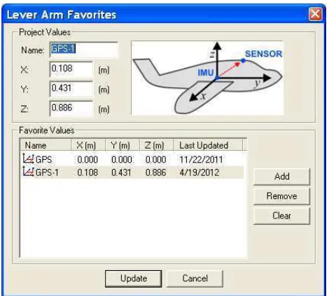
When post processing the GPS-IMU data e.g. with NovAtel’s Waypoint Inertial Explorer, the lever arms can be directly entered. Even the software is able to estimate the lever arms automatically; the results of proper measured lever arms deliver a far better accuracy.
When using a stabilized platform we have to be aware on a so call called floating Lever arm. The IMU moves related to the GPS-Antenna, depending on the compensation activity. Roll, pitch and Heading compensations create changes in the lever arms. This will be discussed in chapter 4.
Figure 2: Applying the leverarms GPS Antenna (here called sensor) to IMU in Waypoint’s Inertial Explorer
3. LEVERARM IMU-SENSOR
Another lever arm exists between the IMU centre and the sensor. This lever arm can be applied directly but can be also part of the misalignment determination. But the measurements of these values are relatively simple. The IMU centre was already discussed, as we use photogrammetric procedures, the
projection centre is what we are going to use on the sensor side. Doing it easy, we can estimate the projection centre on a right-angled axis on the Imaging chip (CCD, Film …) with the focus length as distance to it. In some cases it is not that easy to detect the plane of the imaging sensor but this is typically documented in the calibration report of the camera producer.
Measuring these values can be done in sub-cm-accuracy. This value must remain constant. NovAtel’s Inertial Explorer enables to apply also these levers directly for the export wizard after post processing the raw GPS-IMU data.
Figure 3: Applying the lever arms IMU to imaging sensor in Waypoint’s Inertial Explorer
4. FLOATING LEVERARMS RELATED IMU-GPS
As mentioned in chapter 2, the antenna-IMU lever arm does not remain constant when using a stabilizer. The IMU must be mounted solid together with the sensor as described in chapter 1; both of them can be then mounted on a stabilizer. The IMU always measures the absolute rotation also of the sensor correctly but the position of the GPS antenna does not remain. The distance changes seem to be small but we have to be aware that the axis related to the IMU system is moving. Depending on the basic length of the 3 axis, a rotation of 10 degree easily can cause several 10th of cm offset in the IMU system.
To achieve proper results in the post processing, we have to add 3 rotation values measured constantly at least with same frequency as the GPS raw data are logged. These are the corrected values related to the basic position of the stabilizer. This basic position (no parking position, no compensation) has to be used also during the measurement of the GPS-IMU lever arms (chapter 2). Because of this, it is important to put the stabilizer in this basic position with a good reproductive accuracy. With AeroStab-Twin we can do that by a simple command and the carrier turntable goes into a middle position without any correction, independent of the actually aircraft position. Then the measurement of the lever arms with a Total station can be carried out. The stabilizer reports its regulation values on all 3 axes in this position as 0.
Together with the raw GPS-IMU data while running a mission, values of the corrected angles must be stored in same or higher frequency than the GPS Raw data. This can be in binary or International Archives of the Photogrammetry, Remote Sensing and Spatial Information Sciences, Volume XXXIX-B1, 2012
XXII ISPRS Congress, 25 August – 01 September 2012, Melbourne, Australia
ASCII format. Important is to have a proper timing in order to synchronise it with the GPS data.
NovAtel’s Inertial Explorer has an import for such files to become part of the post-processing Kalman filtering. It dramatically enhances the accuracy of the position and attitude results.
Figure 3: Import definition of stabilized mount data in Waypoint’s Inertial Explorer for solving floating lever arms.
5. POSTPROCESSING FEATURES
There are various tools on the market to postprocess GPS Data. Important is to combine GPS and IMU data into a common prostprocessing procedure. This is possible with NovAtel’s Inertial Explorer where already a selection of different Kalmanfilterstates are implemented. There must be used different kalmanfilervalues for the various IMUs, the way of processing (Basestation, ppp…) and the dynamic modes (car, aircraft…). The software provides various modules to control the quality.
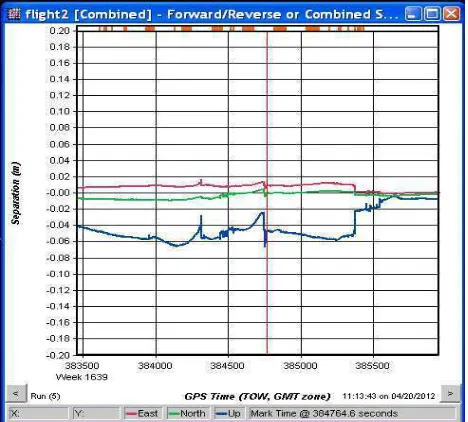
Figure 4: Comparison of forward and backward processing of GPS IMu data in Waypoint’s Inertial Explorer
An excellent tool is the comparision of the forward and backward calculation thas enebles a rather reliable control of the achieved data accuracy. This software is capable to use GPS-IMU leverarms, IMU Sensor leverarms, floating leverarms off a stabilizer and also the possibility to apply misalignment values (borside angles). Beside that, transformations into metric coordinte systems are supported.
6. MISALIGNMENT ANALYSIS
The so called boresight angles are better described as misalignment values. Typically they consist of 3 rotation values only but also can be enhanced by 3 shift parameters to solve remaining inaccuracies in the position. Depending on the proper determined levers mentioned in chapter 2 and 3, there is a remaining set of 3 rotations resulting from the mounting as already discussed in chapter 1. To solve this, a calibration mission taking aerial images over a test field has to be performed. The idea about this procedure is to process images with photogrammetric aero-triangulation methods independent from the results of the direct referencing device and finally to compare the calculated orientation parameters with the directly stored ones in order to achieve systematic offset. For that, a small test field hast to be used with a convenient number of GCPs to result in a proper and reliable aero-triangulation. It is recommended to use at least 2 strips crosswise to achieve a double flown block of data that represents 4 flight directions. Better is to have each 4 lines which results in 8 lines and each direction twice for redundancy. The software Bingo can solve AT-tasks very reliable and is able to detect blunders easily. Automatic tie-point matching with a proper Bundle Block adjustment is a must. A special version of bingo just for such calibration procedures is available. The selected GSD hast to meet the expected GPS accuracy, the flight altitude influences the importance of the resulting angles Omega, Phi and Kappa. To meet the accuracy of the IMU, these aspects have to be taken into account. Such a mission can be used also to calibrate the camera as long as enough 3D structures are available and/or a mission in other altitudes can be performed.
Figure 5: Calculation of the boresight angles in Waypoint’s Inertial Explorer
The determination of the misalignment is relatively easy. The aero-triangulation gives results for each image in X, Y, Z coordinates and rotation values for Omega, Phi and Kappa. Since the definition of Omega, Phi and Kappa is different from Roll, Pitch and Heading, a rotation matrix on basis of the used International Archives of the Photogrammetry, Remote Sensing and Spatial Information Sciences, Volume XXXIX-B1, 2012
XXII ISPRS Congress, 25 August – 01 September 2012, Melbourne, Australia
coordinate system has to be used. After then, the values can be compared and the systematic difference is visible. The achieved misalignment values can be used in NovAtel’s Inertial Explorer software. It is also possible to do the comparison in the software directly.
7. CAMERA CALIBRATION
Metric mid format cameras typically are sold with a calibration protocol that states the calibrated focal length, the ppa respectively the pps and the radial symmetric distortion. These parameters are important for the internal orientation. In contrast to the first metric mid format cameras, sold some years ago, the stability of the mounting between CCD Chip and Lens is much more stabile than before. This is important for direct referencing. In the past mainly the offset appeared unstable which has a direct influence on the position accuracy.
Nevertheless the camera has to be calibrated from time to time and in fact an “on the fly” calibration over a test field gives more reliable results than just a laboratory method can provide. Actually the same test field as used for the misalignment determination can be used in order to get an independent Image orientation with a proper AT done.
As long as the test field supports suitable structures for a proper tiepoint matching, the overlaps are convenient (min, 60/30%) and enough GCPs are available, at least the PPS and the radial distortion can be determined. The focal length can be estimated very close to the real values, however to do that properly, either significant distances in the Terrain or different flight altitudes have to be performed.
The Software package Bingo can solve this issue with special tools to achieve a reproducible Camera calibration. For that, a aero-triangulation has to be performed using sufficient number of GCPs and good relative orientation with manually or automatically selected tie-points.
Figure 6: Calculation of the symetric radial distortion based on a calibration performed in Bingo
8. FINAL DIRECT REFERENCING
Taking all these effects into account, direct referencing can be used either as single image method, or as AB-GPS-IMU data as GCP free adjustment in a bundle block adjustment with additional tie points. The quality of only directly referenced data typically is lower than AT’ed results because no control and no additional adjustment can be performed. Depending on
the use of the data, this might be acceptable e.g. in case of rapid data access for disaster or environmental monitoring. The use of aero triangulation methods solves both, a better agreement between the single images and a better and reliable all over accuracy. Even no GCPs are entered, a possible final error just remains in a slight position and height offset of the entire image block instead of image to image distortions.
9. LITERATURE
BARMETTLER,A.,NEBIKER,S.,KEMPER,G.,KOCH,C,SCHMUTZ, M., STUTZ, C., PETER, M., (2010) airAGro – Fernerkundungslösung für die Agronomie auf der Basis von Leichtflugzeugen und Minidrohnen. 3 Ländertagung der DGPF, OVG und SGPBF Wien.
KEMPER,G. (2006): Spezialapplikationen in der luftgestützten
Fernerkundung- Preiswerte Systeme, Plattformen und Trägersysteme– Angewandte Geographische Informationsverarbeitung XII – Agit 2006, Wichmann, Heidelberg
KEMPER, G., LI HONGBO, PAULY, K. † (2008): New airborne
Sensors and Platforms for specific applications in Photogrammetry and remote sensing; Proceedings of the ISPRS Congress 2008 in Beijing
KEMPER, G. (2010): Neue luftgestützte Sensoren und
Plattformen für verschiedenste Aufgaben in der Fernerkundung. 3 Ländertagung der DGPF, OVG und SGPBF, Wien.
KREMER,J.,KRUCK,E.J. (2003): Integrated Sensor Orientation –Two Examples to show the Potential of simultaneous GPS/IMU and Image Data Processing;
ISPRS Workshop
KRÖPFL, K:, KRUCK, E., GRUBER, M., (2004): Geometric
calibration of the digital large format aerial camera UltraCamD, ISPRS Symposium Istanbul Comm. I, WG I/2.
KRUCK,E.J. (2006): Simultaneous Calibration of Digital Aerial Survey Cameras; EuroSDR Camera Calibration Workshop, Castelldefels, January 2006, Presented Paper
International Archives of the Photogrammetry, Remote Sensing and Spatial Information Sciences, Volume XXXIX-B1, 2012 XXII ISPRS Congress, 25 August – 01 September 2012, Melbourne, Australia