UNWRAPPING HIGHLY-DETAILED 3D MESHES OF
ROTATIONALLY SYMMETRIC MAN-MADE OBJECTS
Bastian Rieck, Hubert Mara, and Susanne Kr¨omker
Interdisciplinary Center for Scientific Computing, Heidelberg University, Germany {bastian.rieck, hubert.mara, kroemker}@iwr.uni-heidelberg.de
KEY WORDS:Archæology, Cultural Heritage, Geometry, High resolution, Rendering, Visualization, Colour
ABSTRACT:
Rotationally symmetric objects commonly occur at archæological finds. Instead of creating 2D images for documentation purposes by manual drawing or photographic methods, we propose a method based on digitally colored surface models that are acquired by 3D scanners, thereby including color information. We then transform these highly-detailed meshes using simple geometrical objects such as cones and spheres and unwrap the objects onto a plane. Our method can handle curved vessel profiles by dividing the surface into multiple segments and approximating each segment with a cone frustum that serves as an auxiliary surface. In order to minimize distor-tions, we introduce a simple quality measure based on distances of points to a fitted cone. We then extend our method to approximately spherical objects by fitting a sphere on the surface of the object and applying a map projection, namely the equirectangular projection known from cartography. Our implementation generates true-to-scale images from triangular meshes. Exemplary results demonstrate our methods on real objects, ranging from small and medium-sized objects such as clay cones from the Ancient Orient and figural friezes of Greek vessels to extremely large objects such as the remains of a cylindrical tower of Heidelberg Castle.
1 INTRODUCTION
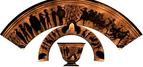
Due to the demand by archæologists for a fast and accurate docu-mentation as well as analysis of small ancient objects, close-range 3D scanners are increasingly used within museums and on exca-vation sites (Sablatnig and Menard, 1992). These man-made ob-jects are manufactured from various materials, and they are often rotationally symmetric. Furthermore, many of them depict lots of details, such as iconographic imagery, ornamental paintings or inscriptions. While parallel projections and cross-sections are used to show the general shape of an object (Orton et al., 1993), the details along the surface have to be unwrapped. Tradition-ally, unwrapping an object is a time-consuming task requiring either a highly skilled draftsperson or special equipment for roll-out photography(Lynch-Johnt and Perkins, 2008). Fig. 1 shows an example of unwrapped conical friezes of an ancient vessel.
1.1 Related work
Previous research in photogrammetry used cylinder fitting for un-wrapping 3D surfaces with known analytical expressions (Karras et al., 1996). Likewise, cartographic projections have already been proved useful for obtaining raster images of paintings on arches and spherical surfaces (Karras et al., 1997). More recent works usestriangle stripsthat are adjusted to the surface of arbi-trary objects in order to unfold them (Massarwi et al., 2007). A detailed body of methods for unwrapping spherical objects can be found in cartography (Grafarend and Krumm, 2006). Our method enables experts of cultural heritage to rapidly compute planar rep-resentations of cultural heritage objects for important tasks such as iconographic analysis. These planar representations cannot be substituted by 3D models e.g. via the Internet, because tasks such as historic interpretations require all parts of an object to be visi-ble.
The simplest geometric primitive for an unwrapping transforma-tion is the cylinder. It has already been used for 3D models of ancient cylinder seals (Pitzalis et al., 2008). Since the cylinder is a degenerate cone, we focus on unwrapping approximately coni-cal objects in the next section. However, as there is a vast number of objects with a spherical shape, we also show how to unwrap a sphere.
1.2 Data format
In the following, we assume that the user is working with 3D representations of cultural heritage objects, such as ceramic ves-sels or cuneiform tablets. We require an object to be specified as atriangular mesh, e.g. inStanford Triangle Format(PLY). This mesh is composed ofvertices, i.e. points inR3
, andfaces, i.e. triangles consisting of three distinct vertices. Theedges of the faces are described implicitly by this representation. Triangular meshes are commonly used and generated by most of commer-cial 3D scanners: Three non-collinear vertices always define a plane and allow for the simple calculation of normals and other properties of the faces.
Figure 1: Unwrapping both figural friezes of a vessel (KHM Inv.-No.3618) by fitting two different cones (Bechtold et al., 2010).
2 DEVELOPABLE SURFACES
In this part of the paper, we will focus ondevelopable surfaces that can be unwrapped without any distortions. The unwrapping transformation is bijective, i.e. it can be reversed without loss of accuracy. For simplicity, we only talk aboutfinite conesandcone frusta, i.e. truncated cones. We will later generalize these tech-niques to unwrap cylinders, as well.
2.1 Fitting a cone frustum
symmet-ric due to their manufacturing process, which uses a rotational plate. In most cases, one can think of vessels as being comprised of several cone frusta. Usually, two or three frusta are sufficient for unwrapping these vessels—see Fig. 1 for a typical example.
For fitting a cone frustum, we let the user interactively specify an axisof the cone as well astwo pointson the surface of an object. We then calculate theheightof the truncated cone by projecting the selected points to the cone axis. The upper and lower radius of the cone are then determined by the position of the points selected by the user. Furthermore, by employing cone frusta, the user can exclude regions of the vessel that are removed upon unwrapping the object. This is useful when the user is interested in a depiction around the middle of the vessel, but does not want to include han-dles or the base of the vessel. From an algorithmic point of view, this approach of cone fitting offers additional possibilities: (i) The process of determining a rotational axis may be automated. In re-cent publications (Mumford and Cao, 2002, Mara and Sablatnig, 2006), methods for automatically finding the best rotational axis have been introduced. (ii) If an axis has been determined, numer-ical fitting methods can be applied in order to find the optimum radii of the cone frustum with respect to some quality measure, such as minimized squared distances (Strutz, 2010).
2.2 Cone distance calculation
When unwrapping an arbitrary object that is not a perfect cone, we want to minimize any distortions occurring due to the trans-formation. To this end, we need to define aquality measure. In the case of a complete cone, we use the distance of each point of an object to the fitted cone as a simple quality measure. When fitting a cone frustum, this method has the advantage of deter-mining whether a point is located above or below the planes of the cone frustum such that distance calculations are not neces-sary. In these cases, the corresponding vertices are skipped and will not be processed any further. This greatly improves the speed of the unwrapping transformation.
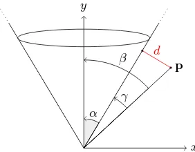
For calculating the cone distance, we assume that the cone is sit-uated in the origin of the coordinate system and opens towards the positivey-axis. The main idea is to use the angleγ=β−α between the position vector of the vertex and the vector along the surface of the cone. With Fig. 2 depicting the required angles, we obtain
dist(p) = sin(γ)· kpk=d, (1) wherekpkis the Euclidean norm of the vector connecting the apex of the cone andp. If the angleβbecomes larger thanπ/2, we setdist(p) :=kpk.
When fitting a cone frustum, we use the same distance calculation as defined above. In addition, we check whether theorthogonal projectionof a query point onto they-axis is outside the frustum. If so, we assign the point a semi-transparent colour. Points whose distances are defined, on the other hand, will be drawn using a heat map colour ramp. This enables the user to see the quality of the fitted cone frustum in one glance—see Fig. 3.
2.3 Unwrapping a cone
Before unwrapping a cone, we first transform the object and the cone into alocalcoordinate system with the axis of the fitted cone being they-axis of the coordinate system. This transformation simplifies later calculations. See Fig. 4 for the current setting. We describe the required formulæ and refer to (Bechtold et al., 2010) for a more detailed derivation. For simplicity, we express the coordinates of the vertices in a conical coordinate system, i.e. one that employs an angleϕiand a heighthito uniquely describe the position of a pointpion the surface of the cone.
β
α γ
p
d
y
x
Figure 2: Angles used for calculating the distance to a cone.
Figure 3: Heat map visualization of the distance to a fitted cone. Due to the high curvature of the vessel (KHM Inv.-No. 3601) larger distances at the middle part of the frustum are visible.
Unwrapping a cone is of the points of the object. Since the maxi-mum height of a point in the conical coordinate system is given as h, whereas the unwrapped cone has a maximum polar radius of s, we require some sort ofscaling. The same applies to the vertex angles: In the conical coordinate system, they span the half-open interval of[0,2π), whereas they are limited by an angleθin the plane of the unwrapped cone. From Fig. 4, we obtain the ratio
2πr θ =
2πs
2π ⇔ θ= 2π
r
s. (2)
Consequently, theangle scale factorλis given as
λ=r
s = sin(α). (3)
For theheight scale factorµ, we observe that a point at heighth will be transformed to heightswhen being unwrapped. Hence, µis given as
µ= s
h =
1
cos(α). (4)
We thus arrive at the following transformation for vertices:
Tc(ϕi, hi) = (λϕi, µhi) (5)
This handles the unwrapping of a cone that is centered along the y-axis of the coordinate system.
2.4 Unwrapping a cone frustum
s
Figure 4: Depiction of the unwrapping process of a cone. Note how angles and heights of the points on the cone are changed.
positions then yield a simple and criterion for the transformation functionTf of a cone frustum:
Tf(ϕi, hi) = (
(λϕi, µhi) hi∈[yl, yu]
undefined else (6)
In practice, we let the user interactively select two points on the surface of a digital object. From these two points, we obtain an upper radiusru and a lower radiusrl, withrl < rubecause we require the apex of the complete cone to be the origin of the coordinate system. We then calculate the respectivey-positions required for Eq. (6):
yu= ru
tan(α), yl=
rl
tan(α) (7)
In this section, we exploited the fact that the cone axis is the y-axis of the coordinate system.
In many cases, the user wants to center the projection of the cone on a certain angle, be it to highlight a certain figurative element on a vessel or to push handles to the side where the cone is split. Following usage in cartography, we call this process selecting a prime meridian. In mathematical terms, this is accomplished by applying afixedoffsetσ ∈ [−π, π)to the projected vertex coordinates, i.e.θi :=θi−σ, and then normalizing the vertex angleθi to a range of[−π, π). Likewise, we have asplitting meridian, i.e. the angle opposite to the prime meridian. This is where the cone will be ‘split’ when being unwrapped to the plane.
2.5 Unwrapping a 3D mesh
So far, we have only discussed the unwrapping of a perfectly con-ical object. In practice, objects areapproximatelyconical at best and may consist of multiple layers. In order to apply the trans-formation described in Eq. (6), we perform the following steps for each vertexpi = (xi, yi, zi)T: (i) Determine coordinates ϕi = arctan (zi/xi),hi =yiof vertex within the conical co-ordinate system. (ii) Obtainradial distanceri =p
x2 i+z
2 i of vertex with respect to cone axis. (iii) Set new coordinates of ver-tex to be(x′i, y′i, z′
i) := (Tf(ϕi, hi), ri).
The second step solves thedepth-sorting problem(Foley et al., 1997, pp. 673–686): Digital objects acquired with a structured light scanner do not have an infinitely thin surface. Instead, each object is composed of an inner and outer shell. The transforma-tion described in Eq. (6) is 2D, which means that points of all layers would be projected on top of each other. By using a radial distance, we obtain a 3D object with the correct depth order—see Fig. 5 for an example.
The mesh consists ofdiscretedata points inR3. Therefore, re-moving all points whose distances are undefined results in trun-cated triangles and rough edges along the upper and lower part
Figure 5: An unwrapped version of an approximately conical ves-sel, UMJ Inv.-No.4611(Karl et al., 2009), that has been rotated to convey the depth information. The highlighted contour is the cross-section at the splitting meridian. This line is identical to the profile lineas drawn by archæologists (Orton et al., 1993).
of the fitted cone. Truncated triangles, in turn, appear as jagged edges in the resulting object. As a remedy, we implemented an algorithm employingsplitting planes. The main idea is to define a plane inHesse normal form, and intersect it with the object. The intersection will create points that are situated on the plane, along the edge of a triangle. By re-triangulating the existing points, the object may be split seamlessly along the plane.
3 NON-DEVELOPABLE SURFACES
In the following, we will handle spheres and theequirectangular projectiononly. However, the methods presented in this section can be generalized to use any cartographic projection or transfor-mation operation.
3.1 Fitting a sphere through four points
If a vessel has spherical characteristics, unwrapping the object by using asphereinstead of aconeyields better results. We let the user choose four points{(xi, yi, zi)T|i= 1. . .4}
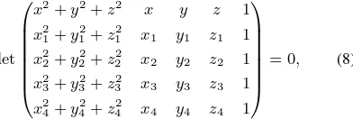
on the surface of the object. By solving a determinant equation,
det
we obtain a general equation for the sphere; see (Osgood and Graustein, 1921), pp. 524–526, for a detailed derivation. Ex-panding the determinant by minorsM1i, we get
(x2
+y2
+z2
)M11−xM12+yM13−zM14+M15= 0.
The implicit equation of a sphere of radiusrcentered at a point
(x0, y0, z0)T Equating the terms of the last two equations yields both radius and center of the sphere:
x0= 1
pi θi ϕi
Ts θ
ϕ
2π π
2
−π 2
p′i= (ϕi, θi)
Figure 6: The equirectangular projection of a unit sphere.
Figure 7: Anaryballos, UMJ Inv.-No.8738(Karl et al., 2009), a vessel with a spherical shape that is well-suited for the equirect-angular projection. Note that the sphere does not envelop the object. This signifies that the object is not perfectly spherical.
3.2 Equirectangular projection of spherical meshes
We assume that points of a perfectly spherical object are given and that the center of the sphere is the origin of the coordinate system. Having described the sphere on which they are situ-ated, we are now able to perform anequirectangular projection, thereby unwrapping the sphere to the plane. To accomplish this, we convert the Euclidean coordinates of the points of the object intospherical coordinates: Let a point inR3
be described by pi = (xi, yi, zi)T. Then the corresponding spherical coordi-nates are given by
ri=
q x2
i +y 2 i +z
2 i
ϕi= arctan
zi
xi
, θi= arcsin
yi
ri
(10)
and we obtain the followingprojection function:
Ts(ri, ϕi, θi) = (ϕi, θi) (11)
Fig. 6 depicts the relation between spherical coordinates and the resulting equirectangular projection. Note that a variant of the equirectangular projections scales all points by the radiusrof the sphere. This ensures that the projection is true to scale.
3.3 Equirectangular projection of arbitrary meshes
Eq. (11) is insufficient for arbitrary meshes: Not all vertices of the object may be situated on the outside of the same sphere. Since we lose alldepth information, different vertices would overlap— this is essentially the same problem that occurs when unwrap-ping arbitrary 3D meshes using cone frusta. We hence again use the radius of the spherical coordinates in order to add depth in-formation. This yields the following procedure for each point pi = (xi, yi, zi)T: (i) Fit a sphere to the object and make the center of the sphere the new origin of the coordinate system. (ii) Determine spherical coordinatesri,ϕi, θi forpiby using Eq. (10). (iii) Set new coordinates of point to be(x′
i, yi′, zi′) T
:=
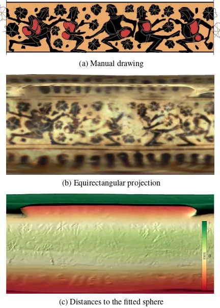
(a) Manual drawing
(b) Equirectangular projection
(c) Distances to the fitted sphere
Figure 8: A comparison of a manual drawing (courtesy of S. Karl) and the equirectangular projection for thearyballosin Fig. 7.
(Ts(ϕ, θ), ri). This transformation ensures that the outside of the originalobject remains the outside of theprojected object. Hence, we again obtain a 3D projection, which may be used for further post-processing, such as detecting curvature, inscriptions, and other surface details. Fig. 7 depicts a vessel that is well-suited for an equirectangular projection along with a fitted sphere. The result of the projection operation for this object is shown by Fig. 8.
4 RESULTS
As this work was originally motivated by the AustrianCorpus Vasorum Antiquorum (CVA)project, we provided25unwrapped vessels forCVAvolume Austria 5 (Kratzm¨uller, 2014). All the final images are orthographic projections and hence true to scale. Our implementation can create high-resolution raster images of the transformed objects by using OpenGL-based tiled rendering techniques. Examples are shown in the previous sections. Fig. 1 depicts the usage of multiple cones for one vessel, while Fig. 10 shows the difference between unwrapping transformations using a cone and a sphere.
Cuneiform tablets from the Ancient Orient have their details rep-resented within geometry. These ancient hand-writings become only visible when properly illuminated e.g. by bright sunlight. While virtual illumination is a global operation, we used local filters based on Multi-Scale Integral Invariants (MSII) (Mara et al., 2010) to compute a false colour texture map that highlights curvature-related features. An example of cuneiform inscription and such texture maps on a clay cone are shown in Fig. 9.
as thePulverturm(powder tower). Together with theInstitute of Geography, Heidelberg University, we documented the present conditions of this part of the castle usingTerrestrial Laser Scan-ning(Siart et al., 2012) with aRiegl VZ-400. Fig. 11 shows the tower and its 3D model.
For the model of the Pulverturm, we extended the techniques from Section 2.5 to unwrap cylinders, as well: A cylinder is a degenerate cone whose upper and lower radius are equal. This equality yields a cone angle ofα= 0, but, following Section 2.4, we can still use an angleϕiand a heighthito uniquely describe the position of a pointpion the surface of the cylinder. With the notation of Section 2.3, Eq. (3) evaluates toλ= 0, while Eq. (4) evaluates toµ = 1. Sinceλ = 0, the transformation function from Eq. (5) maps all anglesϕito0, which is incorrect. We han-dle this by settingTcyl(ϕi, hi) = (rϕi, hi), whererdenotes the radius of the fitted cylinder. Scaling the angleϕiwithrensures that the transformation is true to scale. Using the previous equa-tion, we then proceed as described in Sec. 2.5. The result of the transformation is shown in Fig. 11.
5 CONCLUSIONS AND FUTURE WORK
The work shown in this article demonstrates the use of elemen-tary geometry to unwrap high-resolution 3D meshes of highly detailed objects of cultural heritage. The presented algorithms were successfully tested on a large number of real-world 3D data from archæological projects. Due to this interdisciplinary work, we can suggest several improvements: (i) For some types of ob-jects, it may be advantageous to use standard cartographic projec-tions. There are many projections available offering a variety of different results: Some preserveangles, while others preserve ar-eas. For further discussion regarding several cartographic meth-ods, we refer to (Grafarend and Krumm, 2006). (ii) Future ad-ditions to our framework will be the usage of primitives such as ellipsoids or parameterizable surfaces. (iii) To improve the color representation, flashlights can be added to cancel shadows dur-ing acquisition of the texture-map of the 3D model as described by (Dellepiane et al., 2010).
ACKNOWLEDGMENTS
We would like to thank Dir. Dr. Alfred Bernhard-Walcher and Dr. Bettina Kratzm¨uller of the collection of antiquities of the Kun-sthistorisches Museum, Vienna, as well as Stephan Karl from Graz Universityfor kindly authorizing us to present images of items from the respective collections. For the collaborative work on cuneiform tablets we thank the Assyriology Group, Heidel-berg University, and theAssur Forschungsstelleof theHeidelberg Academy of Sciences and Humanities.
For data acquisition and post-processing of the terrestrial laser scan data, we thank Markus Forbriger and Larissa M¨uller of the Institute of Geography, Heidelberg University. Access to the Pul-verturmwas kindly granted byHeidelberg Castle administration and plans were provided by Dr. Claudia Mohn.
REFERENCES
Bechtold, S., Kr¨omker, S., Mara, H. and Kratzm¨uller, B., 2010. Rollouts of Fine Ware Pottery using High Resolution 3D Meshes. In: Proc. VAST Int. Symp. on Virtual Reality, Archaeology and Cultural Heritage, Paris, France, pp. 79–86.
Dellepiane, M., Callieri, M., Corsini, M., Cignoni, P. and Scopigno, R., 2010. Improved Color Acquisition and Mapping on 3D Models via Flash-based Photography. Journal on Comput-ing and Cultural Heritage.
Foley, J. D., van Dam, A., Feiner, S. K. and Hughes, J. F., 1997. Computer Graphics: Principles and Practice in C. 2nd edn, Addision-Wesley Professional.
Grafarend, E. W. and Krumm, F. W., 2006. Map projections. Springer.
Karl, S., Modl, D. and Porod, B. (eds), 2009. Katalog Arch¨aologiemuseum. Schild von Steier, Vol. 22, Phoibos Verlag, Graz, Austria.
Karras, G. E., Patias, P. and Petsa, E., 1996. Digital monoplotting and photo-unwrapping of developable surfaces in architectural photogrammetry. Int. Arch. Photogramm. and Remote Sensing XXXI, Part B5, pp. 290–294.
Karras, G. E., Patias, P., Petsa, E. and Ketipis, K., 1997. Raster projection and development of curved surfaces. Int. Arch. Pho-togramm. Remote Sensing XXXII, Part 5C1B, pp. 179–185.
Kratzm¨uller, B., 2014. CVA ¨Osterreich 5: Attisch Geometrische, Protoattische und Attisch Schwarzfigurige Vasen Band 1. Verlag der ¨Osterreichischen Akademie der Wissenschaften.
Lynch-Johnt, B. A. and Perkins, M., 2008. Illustrated Dictionary of Photography: The Professional’s Guide to Terms and Tech-niques. Amherst Media Inc.
Mara, H. and Sablatnig, R., 2006. Orientation of Fragments of Rotationally Symmetrical 3D-Shapes for Archaeological Docu-mentation. In: Proc. 3rd Int. Symp. on 3D Data Processing, Vi-sualization, and Transmission, pp. 1064–1071.
Mara, H., Kr¨omker, S., Jakob, S. and Breuckmann, B., 2010. GigaMesh and Gilgamesh - 3D Multiscale Integral Invariant Cuneiform Character Extraction. In: Proc. VAST Int. Symp. on Virtual Reality, Archaeology and Cultural Heritage, pp. 131–138.
Massarwi, F., Gotsman, C. and Elber, G., 2007. Papercraft Mod-els using Generalized Cylinders. In: Proc. 15th Pacific Conf. on Computer Graphics and Applications, pp. 148–157.
Mumford, D. and Cao, Y., 2002. Geometric structure estimation of axially symmetric pots from small fragments. In: Proc. Intl. Conf. on Signal Processing, Pattern Recognition, and Applica-tions, pp. 92–97.
Orton, C., Tyers, P. and Vince, A., 1993. Pottery in Archaeology. Cambridge University Press.
Osgood, W. F. and Graustein, W. C., 1921. Plane and solid ana-lytic geometry. The Macmillan Company.
Pitzalis, D., Cignoni, P., Menu, M. and Aitken, G., 2008. 3D enhanced model from multiple data sources for the analysis of the Cylinder seal of Ibni-Sharrum. In: Proc. 9th Int. Symp. on Virtual Reality, Archaeology and Cultural Heritage, pp. 79–84.
Sablatnig, R. and Menard, C., 1992. Stereo and structured light as acquisition methods in the field of archaeology. In: Muster-erkennung 1992, Springer, pp. 398–404.
Siart, C., Ghilardi, M., Forbriger, M. and Theodorakopoulou, K., 2012. Terrestrial laser scanning and electrical resistivity tomog-raphy as combined tools for the geoarchaeological study of the Kritsa-Latˆo dolines. G´eomorphologie (1), pp. 59–73.
Steible, H., 1991. Die neusumerischen Bau- und Weihinschriften I. Freiburger altorientalische Studien, Vol. 9, Steiner.
(a) Illuminated 3D model
(b) Distances between the cone and the 3D model, unwrapped model, and color ramp.
(c) MSII filter responses, unwrapped model without virtual illumination, and grayscale ramp.
Figure 9: 3D model of a building inscription with cuneiform characters on aTonnagel(clay cone), ca.2200–2000B.C.,Sammlung des Seminars f¨ur Sprachen und Kulturen des Vorderen Orients, Assyriologie, Universit¨at Heidelberg. For information about the inscription and its known 451 ancient duplicates see (Steible, 1991,Text Ur-Baba 7).
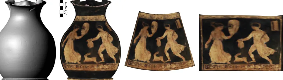
Figure 10:Oinochoe, UMJ Inv.-No. 4181 (Karl et al., 2009). From left to right: A scanned version of the object, an unwrapped variant using a cone, and the result of the equirectangular projection. Unpainted parts of the vessel have been discarded.