PRECISE HEAD TRACKING IN HEARING APPLICATIONS
A. M. Helle a, J. Pilinski a, T. Luhmann a
a IAPG, Institute for Applied Photogrammetry and Geoinformatics, Jade University of Applied Sciences, Oldenburg, Germany -
(helle, iapg, luhmann)@jade-hs.de
Commission V and III, WG V/5 and WG III/3
KEY WORDS: Tracking, Medicine, Hearing, Development, Hardware, Infrared, Measurement techniques
ABSTRACT:
The paper gives an overview about two research projects, both dealing with optical head tracking in hearing applications. As part of the project “Development of a real-time low-cost tracking system for medical and audiological problems (ELCoT)” a cost-effective single camera 3D tracking system has been developed which enables the detection of arm and head movements of human patients. Amongst others, the measuring system is designed for a new hearing test (based on the “Mainzer Kindertisch”), which analyzes the directional hearing capabilities of children in cooperation with the research project ERKI (Evaluation of acoustic sound source localization for children). As part of the research project framework “Hearing in everyday life (HALLO)” a stereo tracking system is being used for analyzing the head movement of human patients during complex acoustic events. Together with the consideration of biosignals like skin conductance the speech comprehension and listening effort of persons with reduced hearing ability, especially in situations with background noise, is evaluated. For both projects the system design, accuracy aspects and results of practical tests are discussed.
1. INTRODUCTION
Video-based tracking methods have been applied in a lot of different fields for many years. The tracking and capture of body movements using cameras is often subsumed by the term motion capture. Applications of this technology can be found in medicine, robotics and in the entertainment industry for computer animation and motion capture for video games and movies. Popular examples are pedestrian detection for advanced driver assistance systems (Enzweiler et al. 2008) and the navigation of tools in surgery (Broers et al. 2007). Available tracking systems differ significantly in measuring accuracy, tracking frequency, measurement volume, costs and other specifications.
In order to ensure robust tracking of fast movements in these applications, frequencies of more than 20 Hz are required. The sensors usually have a resolution of about one megapixel, and synchronization between cameras can be utilized by a joint trigger unit.
The achievable measuring volume depends on various factors such as sensor resolution, focal length, image scale and also the numbers of used cameras. Generally it can be said that at constant conditions for the image scale, a larger volume can be achieved if the aperture angle is larger and the appropriate configuration uses more cameras.
2. OPTICAL TRACKING METHODS
Currently there is a wide range of optical tracking methods. In general, two- and three-dimensional tracking and the various methods of image analysis are to be differentiated. In marker-based approaches, for example, retro-reflective targets were frequently used in combination with infrared illumination. Other approaches work without signalization and use methods of pattern recognition or pattern matching (D'Apuzzo 2003). This paper deals with marker-based tracking.
Both presented techniques, the single and stereo camera tracking approaches, are implemented in the AXIOS software library Metrology that is used to process the images from the camera systems SingleCam and CamBar B2. The SingleCam used for first tests for the low-cost application has a resolution of 776 * 582 pixels with a focal length of 8 mm and a frame rate of up to 64 Hz. The camera is used to calculate the 6DOF parameters between two rigid bodies (locators) based on space resections (Luhmann 2009, see section 2.1). The specified measurement accuracy is 3 mm maximum length measurement deviation between two single points in the measurement volume. The CamBar B2 (Fig. 7, left) consists of two cameras with a sensor size of 736 * 582 pixels, a focal length of 8 mm and a frame rate of up to 64 Hz. The measurement accuracy is specified to 1 mm of maximum length measurement error between two single points in a measurement volume of ~1.9 m³ and 0.25 mm for the 3D positioning accuracy of a point field. Both camera systems are pre-calibrated by the system supplier and equipped with an optical band-pass filter, which is permeable for the infrared range (810 nm). As retro-reflective targets reflect the light back into the direction where it comes from an infrared lighting is already integrated so that observed retro targets are perfectly visible for both of the camera systems.
2.1 Single camera tracking
By using just one camera, the orientation and position between two objects (locators) can be determined by a spatial resection if both are observed in the same image.
�′= X: desired position of the same point P in XYZ x0, X0: projection center in xyz and XYZ R: rotation matrix of the probe in XYZ.
A special problem for single camera 6DOF tracking is given by the need of robust point identification. Since the points appear in only one image, epipolar matching of corresponding points cannot be performed. The AXIOS system uses a sophisticated identification scheme based on individual point distribution of the locator design.
2.2 Stereo tracking
Tracking of a probe with two cameras instead of one offers a number of benefits, such as enhanced robustness (solving occlusions), simpler point identification (epipolar geometry) and improved 3D accuracy.
Stereo tracking systems allow to determine the 3D coordinates of a probe in an object coordinate system XYZ by calculating a spatial intersection from two synchronized, oriented images. The probe has a local coordinate system xyz that is determined through a photogrammetric calibration.
1. Transformation of image coordinates of left and right image
�′
2. Components of the basis
��=�02− �01
��=�02− �01
��=�02− �01
(6)
For the common spatial intersection the crooked rays intersect in XY-plane in the height of the calculated point of the probe.
�=�1=�2
3. TRACKING IN CHILDREN HEARING TESTS 3.1 Audiological background
The directional perception of sound events is a process of binaural hearing in which the ear uses the time and intensity differences of an incoming sound signal to determine the horizontal direction. In general, high-frequency signals can be localized worse than low-frequency. The hearing system primarily uses volume level differences (Interaural Level Difference, ILD) at the higher frequencies and the time delay (Interaural Time Difference, ITD) at lower frequencies (Plotz et al. 2013, Geldermann 2012). Within the project "Evaluation of acoustic sound source localization in children (ERKI)" an upgradable examination unit is developed which allows, based on the “Mainzer Kindertisch”, to analyze the capability for localizing sounds by (elementary) children using virtual sound sources. The task of the research project ELCoT was to develop a low-cost 3D measurement system for detection of head and arm movements in real time, which can be applied to new hearing tests in the cooperative project ERKI. Since high investment costs for the distribution of the examination unit with doctors and specialized clinics are not acceptable, the challenge lies in the development of a particularly cost-effective system, taking into account the required accuracy of 1-2° (Pilinski et al. 2014).
3.2 System setup
Figure 1. “Mainzer Kindertisch” with camera system, test person and loudspeaker semicircle
Compared to a conventional hearing test scenario with only five speaker positions, this setup provides improved capabilities. It is possible to generate sound events at each position in the semicircle by using phantom sound sources. This makes it necessary to develop an objective detection of the pointing motion to the acoustic event from the test person. The manual detection by the investigator, as it is currently common practice, would not be sufficient because of the required accuracy of 1-2° for the angle of the pointing gesture. As a pointing device a toy drill (Theo Klein / Bosch cordless drill) equipped with a probe is used. This is child-friendly and by the given ergonomic grip of the cordless drill it is ensured that the volunteer points in the targeted direction (Fig. 2, left). An infrared remote control has been integrated which enables the test persons to confirm the indicated direction by pressing a button. That means when the test person activates the button of the toy drill, the currently indicated direction (angle in degrees) is saved for the later analysis of the directional hearing.
In addition to the pointing gesture, the head movement of the test person will be tracked. On the one hand, a start signal of the hearing test is given, which means a new measurement can be started when the test person is looking straight ahead. On the other hand, additional information may be obtained with regard to how the person behaves during the test and if one turns his head, for example, to the sound source. For the head tracking the test person is wearing a light head belt. The head belt is also equipped with a probe that is tracked by the camera system continuously (Fig. 2, right). The mount is fixed to the head of the test person as good as possible and does not cover the ears, so as not to affect the incoming audio signal and the hearing.
Figure 2. Left: Toy drill with probe, Right: Head mount with probe
Since the 6DOF movement of the two movable components (head and pointing tool) have to be registered within the loudspeaker coordinate system, a number of local reference points are attached to the table which are measured simultaneously with the other locators.
The recorded directions and calculated angles should be visible through an optical feedback to the test persons. So it is one goal to visualize the current pointing direction of the test person by using a LED strip. The light strip serves as a control for the test person. The real-time capability (20-30 fps) of the system is an important condition for this visualization, as is the suitable syn-chronization capabilities to the audiology system and LED strip.
The low-cost tracking system has been developed on the basis of an available professional AXIOS 3D SingleCam system connected with the AXIOS 3D library Metrology that is able to detect and track targeted probes. For the further development of the measuring system leading to a low-cost solution, a cost-effective USB industrial camera of the Visiosens GmbH was chosen. The main features are shown in Table 1:
Image Sensor 1/3” Aptina CMOS
monochrome Effective pixels 1280 x 960
Pixel size 3.75µm
Mount S-mount
Lens 5mm focal length
Table 1. Features of the USB industrial camera
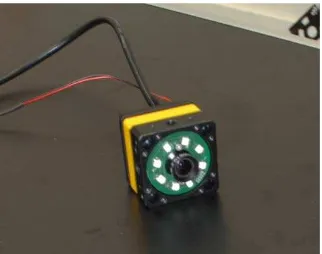
In order to measure retro-reflective targets in an image, suitable lighting is necessary. Therefore eight LEDs are mounted around the lens, similar to a ring light (Fig. 3). The LEDs have an additional power supply. The industrial camera is a quite compact one; due to space restrictions an S-mount was chosen for the lens.
positions for the comparative measurements. The deviations of the low-cost camera system from the professional system are shown in Figure 4.
Figure 4. Reference measurement; deviations of the horizontal angle
low-cost camera system and, for comparison, with the AXIOS 3D SingleCam was performed. Both camera systems were used at the same time and in each case the angle indicated by the test person was determined.
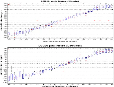
The study involved ten normal hearing test persons, which were divided into two groups. Group A first got sound sources with “Pink Noise” and Group B first got sequences of the International Speech Test Signal (ISTS). This was followed by a change of the noise.
The boxplots (Fig. 5) show similar results in the localization performance for both camera systems. The dispersion of the indicated locations with both cameras is greater at the sides, which corresponds to the human hearing.
The two systems produced some outliers, where either the test person might have been inattentive or the camera detected a wrong angle. Besides, the low-cost camera was not able to capture some angles, which has to be improved. But, altogether, the low-cost system can be used like the professional system.
4. TRACKING IN WAVE FIELD SYNTHESIS SYSTEM 4.1 Audiological background
For the normal-hearing population the human sense of hearing allows to filter background noise in a conversation to concentrate on the significant sounds. This is known as “cocktail party effect”. Hearing impaired people often have problems concentrating in a conversation as they are distracted by other speakers or noise sources e. g. in a cafeteria. They have a higher listening effort. The term ‘listening effort’ refers to the attention and cognitive resources required to understand speech (Gosselin et at. 2011). In recent years, hearing aid manufacturers have made it a priority to find ways to improve the performance of hearing aids in noisy listening situations. One way is through the development of signal-processing algorithms such as noise-reduction algorithms (Desjardins et al. 2014).
As head movements affect the spatial hearing but are not needed for directional hearing, one aim of the research project framework “Hearing in everyday life (HALLO)” is to analyze how far hearing impaired people use head movements to better locate sound sources and thus better understand complex stimuli. Several experiments contribute to the development and evaluation of measuring parameters and techniques to quantify the listening effort. The observation of biosignals like skin conductance and heart rate during hearing tests should allow conclusions on the speech comprehension as there might be a correlation (Mackersie et al. 2015). The rotation of the head is required to be calculated with a relative accuracy of 1°.
4.2 System setup
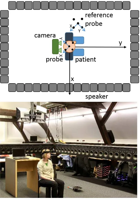
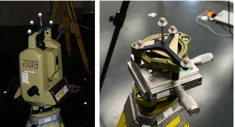
The experimental setup consists of a wave field synthesis system in the center of which a patient listens to complex acoustic events (Fig. 6). The wave field synthesis system is a set of 104 speakers arranged in a rectangle that can reproduce complex acoustic stimuli. After hearing a stimulus the patient rates its level of difficulty. During the experiment several biosignals and the head movement are recorded. For observing the biosignals a NeXus 10-MKI is used. For tracking the head movement an AXIOS stereo camera CamBar B2 (Fig. 7, left) and the proprietary AXIOS software library Metrology are used. The camera is attached to a wooden beam above the patient to have a good view on the markers used. Head movements during listening can be classified into three groups: tilting, inclining and rotating (Blauert 1997). Thus the test person wears a light head belt with a targeted probe that represents the head movement in 6DOF and is tracked by the camera system continuously (Fig. 7, right). The head belt is fixed to the head of the test person as firmly as possible and does not cover the ears, so as not to affect the incoming audio signal and the hearing.
To compensate slight camera movements during the test a reference probe on the floor is observed continuously. All movements of the head probe are related to the reference probe. To associate the head movement with the direction of the stimuli which is generated by the wave field synthesis system, all data have to be transformed into the same coordinate system. For this purpose a simultaneous camera calibration is performed to measure the wave field synthesis system together with the reference probe that represents the origin of the coordinate system.
Figure 6. Patient is sitting in the center of the wave field synthesis system. The stereo camera above observes the points on the patient's head and the reference system on the floor simultaneously
Figure 7. Left: AXIOS stereo camera CamBar B2, Right: light head belt with a targeted probe
As the Metrology library offers the 6DOF parameters (x, y, z, ω, φ, κ) for each probe in the camera coordinate system, a transformation of the probe at the head belt into the coordinate system of the wave field synthesis system is calculated. In order to get the rotation and translation of the head, the relative movement to the first captured frame is calculated.
connected to the floor, slight camera movements may occur during the hearing tests. In order to check the impact of vibration of the wooden beam, a measurement with the vibration sensor ZEB/GS3T (Fig. 8) was performed. The vibration in x-, y- and z-direction was sent to an oscilloscope. Fig. 9 displays the vibration while a person walks through the room. The xy-plane lies parallel to the aluminum plate. The diagram maps a measurement over 120 ms. The sensitivity of the vibration sensor is specified to 10 mV
mm s⁄: if the oscilloscope displays an amplitude of 10 mV, this corresponds to a vibration speed of 1 mm/s. The deviation of the wooden beam in z-direction is calculated as follows:
A = 4 mV (amplitude) ≙v (t) = 0.4 mm/s (vibration speed)
τ = 0.06 s (cycle duration) f = 1 / τ = 16.67 Hz (frequency)
ω = 2 ∙π∙f = 104.72 1s (angular velocity)
x0 = v0 / ω = 0.00382 mm (deviation of the wooden beam)
Figure 8. Top view (left) and side view (right) of the vibration sensor. The cable ties only are for security reasons.
Figure 9. Measured vibration speed in x- (red), y- (green) and z-direction (violet) while a person walks through the room
As shown in Fig. 9, significant vibrations occur. Therefore a stable reference coordinate system provided by fixed targets (Fig. 6) is used to compensate relative movements between camera and loudspeaker system, as described in section 4.2.
Two experiments are conducted in order to verify the measurement accuracy of rotation and position of the head: a targeted probe is successively fixed to a compound slide and a tachymeter Leica TC2002 is used to observe the shifting in x- and y-direction and horizontal torsion with the AXIOS CamBar
Figure 10. Experimental setups for verifying the accuracy of a rotation (left) and position (right).
Compound slide x-direction 0.1 mm y-direction 0.1 mm
Tachymeter angle 0.15 mgon
Table 2. Accuracy of compound slide and tachymeter used for verifying the measurement accuracy
For the three dimensional reconstruction of the wave field synthesis system a Nikon D4 camera with a wide-angle lens is used. A photogrammetric multi-image configuration has been acquired that allows for the 3D measurement of relevant points of the loudspeaker system and of the reference system points as well. In addition, the camera can be calibrated simultaneously.
The simultaneous camera calibration has been tested in a laboratory before it will be applied to the wave field synthesis system. Coded targets were distributed among the whole measuring volume and scales were laid out in all axial directions (Fig. 11). The reference probe has been calibrated before to represent the origin and provide approximate values for the bundle adjustment. The relation between both coordinate systems is established through the origin of the wave field synthesis system. It is defined by the intersection of both diagonal lines of the rectangular wave field synthesis system. To measure the diagonal lines during the calibration the edges are marked with targets. If the head movement and the origin of the wave field synthesis system are known in one coordinate system the head movement can be transformed into the coordinate system of the wave field synthesis system and compared to the stimuli generated by it.
-6,0E- 03 -4,0E- 03 -2,0E- 03 0,0E+00 2,0E-03 4,0E-03 6,0E-03
0 10 20 30 40 50 60 70 80 90 100 110
S
ch
w
in
g
u
n
g
[
v
]
Zeit [ms] Schwingung des Balkens (Person läuft durch den Raum)
CH1
CH2
Figure 11. Coded targets in a 50x50 cm grid and scales for the simultaneous camera calibration. The origin of the measured system is defined in one corner of the reference probe.
5. CONCLUSION AND OUTLOOK
In this paper the system design, accuracy aspects and (first) results of two research projects were presented. For the project ELCoT a low-cost camera tracking solution was presented using an USB industrial camera with LED ring light and a filter to block visible light. The developed solution is practicable and can be used to measure directional hearing. Only the robustness of the entire system should be increased in the future.
To make the system as cost-effective as possible more test series with cost-effective, adhesive markers (Fig. 12) should be performed. First tests have already shown that low-cost probes (material costs of a few euros) are also suitable for the hearing tests with respect to the required accuracy. Furthermore, the robustness of the system should be increased and outliers should be eliminated reliably. In general, the low-cost measurement system can be transferred to other applications.
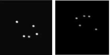
Figure 12. Left: Measuring image of a low-cost probe, Right: Measuring image of the toy drill probe with professional markers
Within the project HALLO a proprietary stereo system is used for tracking a patient's head during hearing tests, performed in a wave field synthesis system. Apart from the head movements other biosignals are analyzed in order to study the speech comprehension and listening effort of hearing impaired people in cocktail party situations.
Extensive test series are planned for the next project stages that will show the real behavior of patients and the relevance of head measurements during hearing events. Currently real test scenarios like a speech conversation in a car or on the street are recorded. These scenarios will be reproduced through the wave field synthesis system to observe the test persons’ behavior and learn how difficult such scenarios appear to them.
Furthermore, another position for the camera system is imaginable. A wide-angle lens could be used to see the targeted wave field synthesis system as well as the test person simultaneously. The advantage of this setup could be that the reference probe is not needed anymore and thus the measuring effort is reduced.
REFERENCES
Blauert, J. (1997): Räumliches Hören. Stuttgart, Hirzel-Verlag
Broers, H. & Jansing, N. (2007): How precise is navigation for minimally invasive surgery? In: International Orthopedics, Springer Verlag Berlin Heidelberg 2007.
D’Apuzzo, N. (2003): Surface measurement and tracking of human body parts from multi station video sequences. Ph.D. Thesis, Institut für Geodäsie und Photogrammetrie, Mitteilungen No.81, ETH Zürich, Schweiz, 2003.
Desjardins, J. L. & Doherty, K. A. (2014): The effect of hearing aid noise reduction on listening effort in hearing-impaired adults. Ear & Hearing, Vol. 35, No. 6, p. 600-610.
Enzweiler, M., Kanter, P. & Gavrila, D.M. (2008): Monocular Pedestrian Recognition Using Motion Parallax. IEEE Intelligent Vehicles Symposium, Eindhoven, The Netherlands, 2008.
Geldermann, C. (2012): Lokalisation von Phantomschallquellen am MAINZER Kindertisch zur Entwicklung eines Diagnose-verfahrens von Auditiven Verarbeitungs- und Wahrnehmungs-störungen. Bachelorarbeit am Institut für Hörtechnik und Audiologie der Jade Hochschule Oldenburg, 2012.
Goebl, M. & Färber, G. (2007): A real-time-capable hard- and software architecture for joint image and knowledge processing in cognitive automobiles. In: Proceedings of the 2007 IEEE Intelligent Vehicles Symposium, pages 734-740, IEEE Press, Istanbul, Turkey, June 13-15, 2007
Gosselin, P. A. & Gagne, J.-P. (2011): Older adults expend more listening effort than young adults recognizing speech in noise. Journal of Speech, Language, and Hearing Research, Vol. 54, p. 944-958, June 2011
Luhmann, T. (2009): Precision potential of photogrammetric 6 DOF pose estimation with single images. ISPRS Journal of Photogrammetry and Remote Sensing, Vol. 65, pp 275-284.
Luhmann, T., Robson, S., Kyle, S., Boehm, J. (2014): Close-Range Photogrammetry and 3D Imaging. 2nd ed., Walter de Gruyter, Berlin, 684 p.
Mackersie, C. L., MacPhee, I. X., Heldt, E. W. (2015): Effect of hearing loss on heart rate variability and skin conductance measured during sentence recognition in noise. Ear & Hearing, Vol. 36, No. 1, p. 145-154.
Pilinski, J., Luhmann, T., Schmidt, K. (2014): Development of a real time low-cost tracking system for medical and audiological problems. LowCost3D – Sensors, Algorithms, Applications, Berlin, 2.+3.12.2014.