Coating in
Primary Reformer’s
Radiant Section
Baskara Aji Nugraha*
PT Kaltim Parna Industri, Kaltim Industrial Estate Bontang, Kalimantan Timur, 75314 Bontang KPI, Jl. Pupuk Raya Km.2 Bontang
Abstract
Kaltim Parna Industri, (KPI), experienced severe fouling on the flue gas side of the coil heat exchangers. This happened on the outer tube side, which some were finned tubes. Although the cause had not clearly been identified, laboratory analysis indicated that the fouling had similar composition with the firebrick. Therefore, preliminary assumption of what causes the problem was firebrick erosion that was carried away by flue gas flow. In order to completely eliminate fouling source and hopefully to reduce cleaning frequency, we planned to coat combustion chamber with special high temperature resistance coating.The result was promising that the material was stable against high temperature and even further helped the operation.
Keywords: convection section, fouling, coating, firebrick, reformer
Abstrak
Kaltim Parna Industri (KPI) mengalami masalah pada coil heat exchanger pada bagian konveksi primary reformer yang memanfaatkan panas flue gas yaitu berupa fouling pada bagian luar tube coil exchanger (finned tube). Pada awalnya belum diketahui sumber penyebab fouling, namun dari hasil analisis laboratorium diketahui bahwa komponen penyusun fouling sama dengan komponen firebrick (batu tahan api). Oleh karena itu diambil kesimpulan bahwa penyebab fouling adalah firebrick yang tererosi lalu terbawa aliran flue gas.
Salah satu cara untuk menghilangkan sumber fouling adalah dengan melakukan coating pada ruang bakar yang terdapat firebrick di dalamnya. Coating dilakukan dengan menggunakan cat khusus yang tahan suhu tinggi yang mampu menahan permukaan fire brick dari erosi.
Kata kunci: seksi konveksi, fouling, pelapisan, firebrick, reformer
Introduction
PT. Kaltim Parna Industri, well-known as KPI, founded on February 13, 1996, has been known as one of leading manufacturer and exporter of ammonia in Asia and Australia. The ammonia plant is designed to produce Anhydrous Ammonia with capacity of 1,500 MT/day along with all supporting utilities. Our vision “To be the most efficient ammonia producer in the world”, embraces High Productivity, Efficiency in Energy, Satisfactory of Market and QSHE (Quality, Safety, Health & Environment).
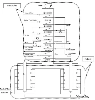
In KPI, plant reforming process consists of two reformers; Primary and Secondary reformers. The primary reformer is divided into two sections: radiant and convection section. Radiant section is located in lower part of the furnace where the burners and catalyst tubes are located. Convection section is located in the upper side adjacent to the radiant section.
KPI’s Primary Reformer is a duplex chamber reformer (having two parallel furnaces) with a
__________
* Alamat korespondensi: baskara.nugraha@kpi.co.id
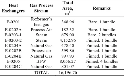
Table 1. Convection section coil heat exchanger
Heat E-0203-2 Steam 4,152.96 Finned. 1 bundle E-0204A Natural Gas 478.40 Finned. 1 bundle E-0202B Process air 599.86 Finned. 1 bundle E-0204B Natural Gas 897.93 Finned. 1 bundle E-0205 BFW 8,056.27 Finned. 4 bundles E-0204C Natural Gas 801.07 Finned. 1 bundle
TOTAL 16,196.76
Figure 1. Primary reformer (radiant and convection section)
Table 2. Fouling composition
Parameters Units Refractory
(reference) Fouling Methods
Appearance - Brown powder Brown dust - Total insoluble
matter % weight 79.64 67.11 Gravimetric
Fe (Iron) % weight 0.10 5.19 AAS
Cr (Chromium) % weight 0.16 0.22 AAS Ca (Calcium) % weight 1.90 0.77 AAS Cu (Copper) % weight Trace Trace AAS Ni (Nickel) % weight Trace Trace AAS Loss on ignition % weight 0.30 0.85 Gravimetric
During process turn around, there was opportunity to inspect the convection section and it was found that exchanger’s coils were severely fouled by red-colored material. Physical appearance indicated that the material was similar to the refractory (radiant wall), which was further confirmed by laboratory analysis.
From this evidence, we concluded that there was evaporation or erosion of refractory material in the radiant chamber. Initial assumption was that the fouling contamination would stop by itself after saturated by the refractory. However, after several cleaning works, we observed that there was no decreasing tendency and therefore
we decided to prevent the source of fouling by coating the firebrick inside radiant section in order to reduce erosion caused by flue gas.
Methodology
Convection Section Cleaning
was chosen due to the following advantages compared to silica:
- High hardness (7.5 - 8 MOHS), not easily break-up and avoiding the convection section dirty.
- High melting point (min. 1,350 C). It is beneficial in case of some left over, it will not add more troubles as operation temperature at the inlet of convection section is about 950C. - Higher specific gravity (SG) of the abrasive grain and low breakdown rate, also resulting in reduced dust level, thus ensuring good operator visibility. Higher SG also means less power required to achieve similar result with requirement (Sukardi and Supriyadi, 2007).
Radiant Section (Combustion Chamber)
Coating
Coating thickness was applied differently, ranging from 1 mm to very thick, to confirm theoretical coverage area of 3 kg/m2 using our chosen furnace coating “Furnascote Novit”. This material was characterized by very high content of zirconia and imparts high resistance to aggressive attacking environments typically encountered at high temperature. Complete chemical composition is as follow: zirconium 62.97%, aluminum 1.63%, calcium 1.37%, magnesium 0.34%, silicon 32.06%, titanium 0.25%, boron 1.1% and fluorine 0.25%.
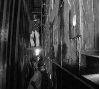
Figure 2. Scafolding installation
A mixture of furnascote in water (25 kg of furnascote in 3.2 Liters water) was applied using a paintbrush. Required quantity was about 2 – 3 kg/m2 in order to achieve a thickness of 1 – 2 mm (arbitrary). It had a good adhesion to the
refractory wall. Then, the sample was aerated several days for natural drying, in order to avoid thermal shock and rapid evaporation upon burner ignition. subcontractor, local based, to install scafolding inside radiant section.
3. Brushing reformer tube and surface preparation. In order to eliminate dust particles attached at tube and radiant wall, we brushed them so the result of coating would be satisfied.
Figure 3. Brushing reformer tube and re-fractory surface hand brushing
4. Coating application. The mixture of furnacecote was spreaded all over radiant section wall.
Figure 4. Application of coating
Results and Discussion
After 9 month operation, we had the opportunity to have visual observation during turn around. Results of the observation were as follow:
deterioration occurred. Further investigation showed that the coating was thicker than the others. Therefore, it was concluded that excessive thickness was not preferable.
Figure 5. After coating (cold condition)
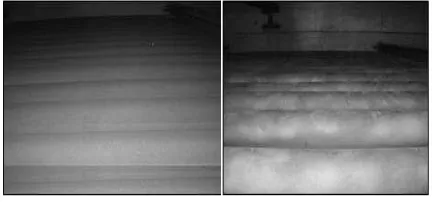
2. Coated surface was smoother than non-coated surface, which is in line with observation during operation. This surface was shiner, which indicated better reflections. Inspection through peephole indicated that radiant wall illuminated brighter than before. It could be said that the radiation heat transfer increased. (Beacon, 2009)
Figure 6. Radiant wall in hot condition before coating (left) and after coating (right).
Red fouling can be removed even from the hardest positions inside the tube bank.
Figure 7. Coil exchangers condition before cleaning (left) and after cleaning (right).
Evaluation was conducted regarding to the consumption of fuel by comparing before and high emisivity of the radiant wall after coating.
Figure 8. Finned coil exchangers condition before cleaning (left) and after cleaning (right).
Based on the visual inspection and evaluation, it could be concluded that coating on the radiant section wall deliver satisfying results. After plant operation for almost one year, the coating remains in a good condition without any damage. In other word, the coating has a good durability toward heat so that annual coating may not be needed.
Table 3. Comparison of fuel consumption before-after coating with NH3 production 1,555 MTPD
Coating Radiant Section in Primary Reformer gives some benefits to KPI on exchanger tubes: - The fouling material is suspected from the
refractory by erosion/evaporation, which enhance the heat reflection of primary reformer wall to the catalyst tube.
- Excessive thickness of coating is not preferable since coating thickness of 1 mm could strongly adhere to the castable surface. - We used to clean convection section once a
year during turn around. After coating radiant section applied, the frequency of convection section cleaning can be reduced.
References
Beacon, J., 2009. Technical Introduction to Cetek Ceramic Coating Technology, PETROTECH, New Delhi, India.
Saefuddin, A., 2007. Catalyst and Technology for Ammonia, Methanol and Hydrogen Produces in Asia Pacific, Topsoe Interactive Technical Seminar, Bali, Indonesia.
Sukardi and Supriyadi, H., 2007. Cleaning of Primary
Reformer’s Convection Section and Combustion
Chamber’s Firebrick Coating, International