NEW DEVELOPMENTS IN BATTERY CHARGERS
by
Emilian Ceuca
Abstract:Electronic equipment is increasingly becoming smaller,lighter and more functional, thanks to the push of technological advancements and the pull from customer demand. The result of these demands has been the rapid advances in battery technology and in the associated circuitry for battery charging and protection.
For many years, nickel-cadmium (NiCd) batteries have been the standard for small electronic systems. A few larger systems, such as laptop computers and high-power radios, operated on “gel-cell” lead-acid batteries. Eventually, the combined effects of environmental problems and increased demand on the batteries led to the development of new battery technologies such as nickel-metal hydride (NiMH), rechargeable alkaline, and lithium ion. These new battery technologies require more sophisticated charging and protection circuitry.
NiCd and NiMH Batteries
NiCd has long been the preferred technology for rechargeable batteries in portable electronic equipment, and in some ways, NiCd batteries still outperform the newer technologies. NiCd batteries have less capacity than lithium or NiMH types, but their low impedance is attractive in applications that require high current for short periods.
Power tools, for example, will continue to use NiCd battery packs indefinitely. Though similar to NiCd types, NiMH batteries have greater capacity. This advantage is offset somewhat by the NiMH battery’s higher self-discharge rate that is approximately double that of the NiCd, which is relatively high to begin with (about one percent of capacity per day). Thus, NiMH batteries are not suitable for applications in which the battery is expected to hold its charge for a long time.
When charging a NiCd battery, the terminal voltage peaks and then declines as the battery reaches capacity. An applied fast-charge should therefore terminate when this voltage starts to drop (when .V/.t becomes negative). Otherwise, the charging current delivers excess energy, which acts on the battery’s electrolyte to dissociate water into hydrogen and oxygen gases. This results in a rise in internal pressure and temperature and a decrease in terminal voltage. If fast-charging continues, the battery can vent (explode).
As a secondary or backup measure, NiCd and NiMH chargers often monitor the battery’s temperature (in addition to its voltage) to ensure that fast-charging is terminated before the battery is damaged. Fast-fast-charging should stop when a NiCd’s .V/.t becomes negative. For NiMH batteries, fast-charging should stop when the terminal voltage peaks (when δV/δt goes to zero).
Trickle charging is simple for NiCd and NiMH batteries. As an alternative to fast-charging, the use of a small trickle current produces a relatively small rise in temperature that poses no threat of damage to the battery. There is no need to terminate the trickle charge or to monitor the battery voltage. The maximum trickle current allowed varies with the battery type and ambient temperature, but C/15 is generally safe for typical conditions.
Lithium-Ion Batteries
The most popular innovation in battery technology over the past few years has been the introduction of lithium-ion batteries. Lithium-ion batteries have a higher capacity than other rechargeable types now in mass production, such as NiCd and NiMH. The advantage of lithium-ion over NiMH is only 10 to 30 percent when measuring the capacity as energy per unit volume, but volumetric capacity is not the only property to consider; weight is also important in a portable device. When measuring the capacity as energy per unit mass, lithium-ion batteries are clearly superior (NiMH batteries are relatively heavy). Because they are lighter, lithium-ion batteries have nearly twice as much capacity per unit mass.
source. To achieve the maximum charge without damage, most lithium-ion chargers maintain a one-percent tolerance on the output voltage. (The slight additional capacity gained with a tighter tolerance is generally not worth the extra difficulty and expense required to achieve it.) For protection, a lithium-ion battery pack usually includes metal oxide silicon field effect transistors (MOSFET) that open-circuit the battery in the presence of under-voltage or over-voltage. These protection MOSFETs also enable an alternative charging method (applying a constant current with no voltage limit) in which the MOSFETs are turned on and off as necessary to maintain the appropriate battery voltage. The battery’s capacitance helps to slow the rise of the battery voltage, but use caution as the battery capacitance varies widely over the frequency, as well as from battery to battery. In some applications, intermittent loads can exceed the main battery’s power capability. A solution to this problem is to provide an additional, rechargeable battery to supply the excess current during a high-load transient. The main battery then recharges the auxiliary battery in preparation for the next transient. Two-way pagers are a good example of this arrangement. Pagers generally run from a single AA alkaline battery, but the load during transmission is too high for an AA battery to handle. An additional NiCd battery powers the transmitter and it can be recharged when the transmitter is off.
Cradle Chargers
For cellular phones and other devices, the preferred battery-charging method involves the use of a separate “cradle charger” into which you place the device or the battery pack (like a baby in its cradle). Because the charger unit is separate, the generated heat is less of a concern than it would be if the charger were integrated into the device.
The simplest circuit for use in a cradle charger is usually a linear-regulator charger.Linear regulators drop the difference voltage (between the dc power source and the battery) across a pass transistor operating in the linear region (hence the name linear regulator). However, the dissipated power (the charging current times the drop across this transistor) can cause overheating if the charger is confined to a small space without airflow.
For example, consider a four-cell NiCd battery charged at 1A. NiCd batteries usually terminate charging at approximately 1.6V or 1.7V per cell, but the voltage can be as high as 2V per cell, depending on the battery’s condition and charging rate. The dc-source voltage must therefore be greater than 4 x 2V = 8V. The voltage level of cells in a fully discharged battery can measure as low as 0.9V each; in this case, the battery voltage is 4 x 0.9V = 3.6V. If the dc source is 8V, the pass transistor sees 8V - 3.6V = 4.4V.
efficiency is even lower because the dc-source voltage must be higher than 8V to account for dropout voltage in the pass transistor and tolerance in the source.
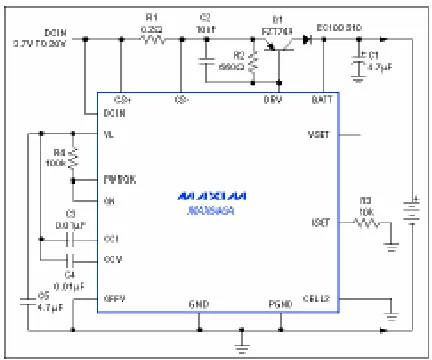
A linear, single-cell lithium-ion charger is suitable for use in a cradle charger (see Figure1). It drives an external power transistor (Q1) that drops the source voltage down to the battery voltage. The external transistor accounts for most of the circuit’s power dissipation; therefore, the controller temperature remains relatively constant. The result is a more stable internal reference, yielding a more stable battery-voltage limit.
Figure 1. Designed for single lithium-ion cells, this battery-charging circuit is ideal for use in a stand-alone cradle charger.
R1 and R3 determine the output current. R1 senses the charging current, and R3 sets the level at which the current is regulated. Current out of the ISET terminal is equal to 1/1,000 of the voltage between CS+ and CS-. The current regulator controls the ISET voltage at 2V; in this case, the current limit [2,000 / (R3 + R1)] is 1A.
Control loops for the voltage and current limits have separate compensation points (CCV and CCI), which simplifies the task of stabilizing these limits. The ISET and VSET terminals allow for adjustment of the current and voltage limits.
Built-In Battery Chargers
critical —not to ensure maximum energy transfer, but simply to minimize heat generation. Heat elevates the temperature, and operation at elevated temperatures shortens a battery’s life. Because this application requires high efficiency over the entire battery-voltage range, the charger should rely on a switching regulator whose power dissipation is relatively low and independent of the input-to-output voltage drop.
The main drawback of switching regulators is the need for a passive inductor/capacitor filter, which converts the switched output voltage to a dc level suitable for the battery. In some cases, the battery capacitance is sufficient to replace the capacitor in this filter; however, as mentioned earlier, a battery’s capacitance can vary greatly with frequency.
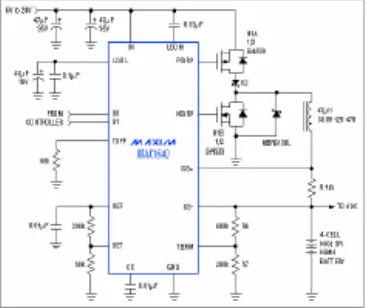
Another drawback of switching regulators is the noise generated by their switching action. This problem can usually be avoided with proper layout techniques and shielding. For applications in which certain frequencies should be avoided, many switching chargers can be synchronized to an external signal — a capability that allows you to shift the charger’s switching noise away from sensitive frequency bands. A linear regulator is generally larger than an equivalent switching regulator because it dissipates more power and requires a larger heatsink. Consequently, the extra time necessary to design a smaller, more efficient switching charger is usually justified. One such design is the four-cell NiCd/NiMH charger shown in Figure 2. It has no provision for terminating the charge; it operates in conjunction with a controller that monitors the voltage across the battery and shuts off the charger when the conditions are met. Many systems already include a controller suitable for this purpose. If your system does not have one, you will need a low-cost, stand-alone microcontroller that includes an on-board analog-to-digital converter. A number of such microcontrollers are available.
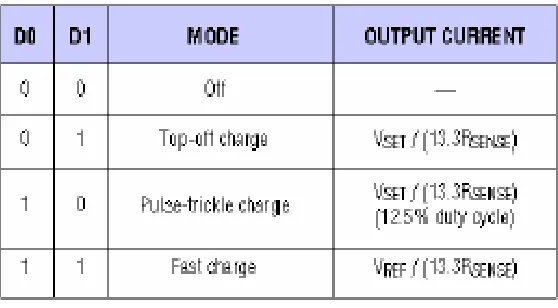
The charger IC (MAX1640) chops the input voltage using a switching transistor (N1A) and a synchronous rectifier (N1B). This chopped voltage is placed across the inductor to form a current source. When the charger is turned off, diode D2 prevents current flow from the charged battery back into the voltage source. In addition to “off,” the MAX1640 operates in one of three modes as determined by the digital inputs D0 and D1: fast-charge, pulse trickle charge and top-off charge (Table 1). In fast-charge mode, the charging current is 150mV divided by the current-sense resistor value (0.1 Ω), or 1.5A. In top-off-charge mode, the voltage at SET produces 24.5 percent of the fast-charge current, or 381mA. The current in pulse-trickle-charge mode is the same as in top-off mode, but it is pulsed with a 12.5-percent duty cycle. Frequency is determined by the resistor connected at TOFF (68 kΩ). In this case, the frequency is 3.125MHz / R3 = 46Hz. The average pulse-trickle current is therefore 0.125 x 381mA = 4.76mA.
Table 1. Charging states for the MAX1640.
The circuit in Figure 2 should terminate a charge when .V/.t equals zero or becomes negative (according to whether a NiMH or NiCd battery is being charged). However, if termination fails to occur, the circuit imposes a secondary voltage limit to prevent the battery voltage from rising too high. As an absolute maximum, the charging voltage for NiCd and NiMH batteries should not exceed 2V per cell, or 8V for the four-cell battery in this circuit. R6 and R7 establish this voltage limit as VLIMIT = VREF [R7 / (R6 + R7)].
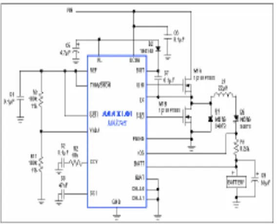
When turned on, this transistor’s source and drain voltages are approximately equal to VIN, but the gate voltage must be higher than VIN to allow the use of inexpensive N-channel MOSFETs. This elevated gate drive is achieved by charging C7 and adding its voltage to VIN.
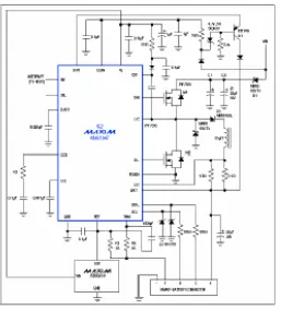
Figure 3.This charger generates a one- percent
accurate charging voltage suitable for charging two lithium-ion batteries in series.
associated with this threshold enables the system to resume charging when a declining battery temperature causes the THM/SHDN voltage to fall 200mV below its 2.3V
threshold.
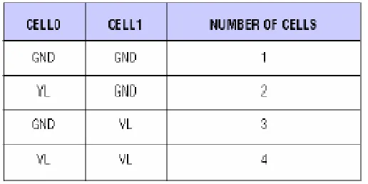
Table 2. Cell-count setting for the MAX745.
Smart-Battery Chargers
Smart batteries represent a new technology that is helping designers and consumers alike. Smart-battery packs include a controller that can “talk” through its serial port to tell an external charger what kind of charging routine the battery requires. This arrangement helps designers because they can design a single charger that handles all the batteries that are compliant with the smart-battery standard.
Smart batteries also benefit consumers, who can replace a given battery without regard to its type as long as the replacement is smart-battery compliant. The smart-battery specification allows any manufacturer to participate in the market, and the resulting competition leads to standardization of products and lower prices.
switched in and out of the host, the fuel gauge is able to maintain the same level of accuracy as it would under continuous operation.
In the smart-battery-compliant charger shown in Figure 4, the controller IC includes an SMBus interface that allows it to communicate with the host computer and the smart battery under charge. Because the switching regulator and its small, power-efficient current-sense resistor cannot achieve a 1mA (minimum) resolution in charging current, the first 31mA (five LSBs) of output current are supplied by an internal linear-current source.
Figure 4. This charger is compliant with the smart-battery specification, and communicates with the host computer and a smart battery via the SMBus
interface.
amplifier. Transistor Q1 off-loads an otherwise heavy power dissipation in the internal linear regulator, which occurs when the input voltage is much greater than the battery voltage. Q1’s base is held approximately 5V below the input voltage. Voltage across the internal current source is less than 5V; therefore, power dissipation in the current source remains below 160mW.
A diode (D3) is placed in series with the inductor to prevent a flow of reverse current aut of the battery. IC2’s high switching frequency (250kHz) permits the use of a small inductor. The circuit accepts inputs as high as 28V and provides pin-selectable maximum output currents of 1A, 2A and 4A.
References
[1] P.A. Jennings, R.J. Ball, P.H. Lever, C Macdonald-Bradley & S. Baker, “W.H.E.E.L.S.: A Statistical Approach to EMC Model Validation”, Proceedings of IEEE 1998 Int’l
Symposium on Electromagnetic Compatibility, Denver USA, August 1998.
[2] “The Foresight Vehicle”, Technology Foresight No.5: Transport, pp 74-83, Office of Science and Technology, HMSO 1995.
[3] D. Ward & S. Lawson, “Numerical Modelling for Automotive EMC”, Proceedings of IEEE 1995 Int’l Symposium on Electromagnetic Compatibility, Atlanta USA, August 1995.
[4] K.S. Kunz & R.J. Luebbers, “The Finite Difference Time Domain Method for Electromagnetics”,
CRC Press,Boca Raton, Florida, 1993.