Temperature Effect on Output Voltage Stability of
Fluxgate Magnetic Sensor
Yulkifli[1,2], Rahmondia Nanda S.[1], Suyatno[3], Mitra Djamal[1] [1]
Theoretical High Energy Physics and Instrumentation (THEPI) Research Division, Faculty of Mathematics and Natural Sciences, Institut Teknologi Bandung
Jl. Ganesa 10, Bandung 40132
[2]
Instrumentation Division, Department of Physics, Faculty of Mathematics and Natural Sciences, Padang State of University, Jl. Prof Dr. Hamka Airtawar Padang
[3]
. Department of Physics, Faculty of Mathematics and Natural Sciences, ITS, Surabaya [email protected]
Abstract - This paper explains the influence of the temperature on the stability of the fluxgate sensor’s output voltage. The stability of a sensor was really influenced by the environment temperature. By the increase of the temperature, causes the increase of the error, moreover the sensitivity of the output voltage is getting larger. For the magnetic field response from -100 uT to 100 uT, it was obtain the output voltage that is ranging from -3.12 to 3.30 Volt, -3.41 to 3.72 Volt, and -4.33 to 4.68 Volt for 25°°°°C, 50°°°°C and 75°°°°C respectively. From the results of the output voltage measurement, the voltage of the sensor's output was varied depends on the applied temperatures. It is also obtained the absolute error value for applied temperatures, these are 0.05V, 0.09V, 0.12V, and the relative error 0.77%, 1,27%, 1,34% for temperature 25°°°°C, 50°°°°C, and 75°°°°C respectively.
I. INTRODUCTION
The use of magnetic sensor in the engineering world, especially in measurement technique and control was increasingly developing in line with the progress of technology [1] in the following areas: for materials magnetic research, geophysics, space, navigation system (detecting transportation goods), mapping earth magnetic field, electronics compass, determining position of an object or distance sensor in the small order[1-6]. For controlling and measurement, it was needed a magnetic sensor with high resolution and has stability concerning to the change in temperature of the environment.
Magnetic sensor represents a sensor exploiting the magnitude of magnetic field intensity around the sensor. The usage of magnetic sensor in the world of technique, especially in measurement technique and control progressively expands in line with the progression of technology [1], such as: for the research of magnetic materials, geophysics, space, navigation system (detecting wafting goods), mapping of earth's magnetic field, electronic compass, and determination of object’s position or sensor apart in small orderi [4,5,7]. For controlling and measuring of distance in the small order required a magnetic sensor with has high precision and resolution.
There are many sensors that can be used to detect magnetic field, e.g.: Hall sensor, magnetic induction, and fluxgate. Hall sensor detects magnetic field using Hall Effect, magnetic
induction using wire coil, and fluxgate using primary and secondary coil. From these sensors, fluxgate has some advantages such as measuring either AC or DC magnetic field; measuring very low magnetic field, having high linearity, having adequate stability, having great sensitivity, reliability, ruggedness, small dimensions, relative simple, and economy [8]
Based on the measurement’s range of magnetic field, magnetic sensor is groped into three categories, low field (smaller than 1 µ G), medium filed (1-10) µG and high field ( above 10 µ G). Those categories can be seen at table 1.
TABLE 1
MEASUREMENT’S RANGE OF MAGNETIC FIELD
According to table 1, it shown that fluxgate magnetic sensor is very compatible to be used in measurement of very weak magnetic field [9]. Due to the potency of fluxgate, it will give an opportunity for this sensor to be applied as sensor apart in measurement of very small order. Furthermore, this sensor also has opportunity to be applied in other quantities such as: pressure, stream, vibration sensor, etc.
because fluxgate sensor uses core that was made from ferromagnetic material.
The ferromagnetic material that often used was: Co68,25Fe4,5Si12,35B15, which also known as Vitrovac and Metglas. Based on the ferromagnetic core Vitrovac 6025 Z datasheet, this material could work well on temperature below 90oC (datasheet 1998).
II. THEORETICAL BACKGROUND
A. Sensor Fundamental
The basic principle of fluxgate sensor's system is comparison of measured magnetic field Bext with a reference magnetic field Bref. The principle is seen on Fig. 1. Magnetic field reference could have shape of the sinusoid, square, or triangle alternating signal. It was excited to the core through the primary coil. The magnetic field that is going to be measured Bext is superposed with Bref magnetic field reference. Then it
was sensed in the core by the secondary coil (pick-up coil) to be evaluated. Fluxgate sensor sensitivity is dependent on core material permeability [10].
Fig. 1. Magnetic field measurement principle: a) with direct method; b) uses magnetic field reference Bref as a comparator against measured
magnetic field Bext. [8,11,12] .
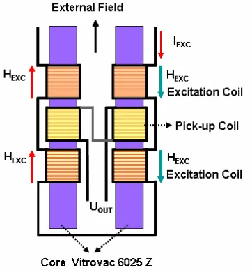
The fluxgate magnetic sensor was made based on characteristics of the ferromagnetic core that has linear response. In the simple construction, the fluxgate magnetic sensor consists of two coils, that is the primary coil for excitation and the secondary coil for pick-up, as shown in Fig. 2.
The excitation coil is used to generate the magnetic field. The principle that happened at excitation coil is the magnetic field that emerged in the solenoid. Where the magnetic field that emerged is resulted from the existence electric field (the Faraday Law). The secondary coil (pick-up coil) is the coil functioned as a sensor to sense the change of magnetic field caused by the excitation coil.
The fluxgate sensor's output was influenced by several things, like density of the magnetic flux, frequency and environment temperature. Because of the existence of these components, it was need an evaluation on the output voltage obtained. In the research that was carried out, it was inspected
the influence of the environment temperature on the stability of the sensor’s output voltage.
Fig. 2. Simple construction of fluxgate magnetic field sensor
The measuring principle is based on the shape of the magnetization curves, which are formed by annealing in accordance with the appropriate principle. A mathematical approach in accordance with the functional principle and the driving current has been made to describe the functional principle of the fluxgate magnetometer. For magnetization curve of Z characteristic and the second harmonic principle, a polynomial approach or piecewise linear function can be used [13].
B. Second Harmonic Fluxgate magnetometer
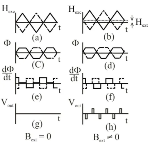
Basic Principle of Operation
Figure 3. Principle of fluxgate magnetic field sensors [14].
One of the most popular magnetometers is the second harmonic fluxgate magnetometer, which came into use in the 1940s. Many different types of second harmonic fluxgate magnetometers have been investigated and developed since then. The advantages of this type of magnetometer are ruggedness, small dimensions, great sensitivity, adequate stability, reliability and economy. Special second harmonic fluxgate magnetometers have reached the highest sensitivity
(b)
Magnetometer
B
extOutput
(a)
Magnetometer
B
extOutput
B
refand the lowest noise of all fluxgate magnetometers. Basic principle of operation shown in Figure 3.
A ferromagnetic core is alternating driven into saturation. The magnetization is a function of the applied field of excitation coil. Pick-up coils measure dΦ/dt. A differential arrangement of pick-up coils leads to a symmetric dΦ/dt when there is no external field applied. The integrated signal is zero. With an external field the symmetry is broken, dΦ/dt shifts and the integrated signal depends on the external magnetic field. When the frequency of the signal is twice of the excitation frequency, a second harmonic readout can be used
C. Transfer Function
The transfer function of a fluxgate magnetometer can be calculated by evaluating the output voltage of the probe by using a polynomial approach [15] and looking for the frequency components which are within the magnetic flux density of the probe core. The use of polynomial approach simplifies the subdivision into frequency components. When a triangular approach is used [16], a more complicated subdivision into Fourier components has to be performed.
Assuming that the probe core is of the linear type, a sinusoidal premagnetization field will saturate
t ω sin H
Href = refmax (1)
It will be superposed on the external magnetic field Hext. The
magnetic field within the probe core will be
(
max)
where N is the demagnetization factor for a linear probe core ii): advantageous to normalize the internal magnetic field strength
to
Hence, the internal magnetic field strength becomes
int normalized polynomial approach of the third order [19]
( )
3where b is the normalized flux density:
0
This approach is used for both the positive and the negative branches of the magnetization curve. The normalized flux density becomes
3 proportional to the external magnetic field strength.
The output voltage of the pick-up coil is proportional to the time derivative of the flux density inside the core:
dt
where N is the number of turns of the pick-up coil and A the cross section of the probe core. The output voltage of the pick-up coil will be reproduced by the normalized output voltage:
dt
t ω sin h
h a ω NA B
Uout2h =−3 0 3 ext ref2 max 2 (14)
or
t ω sin K h
Uout2h= ext 2 (15)
as a linear approximation where K is a constant including the demagnetization factor, the peak value of the premagnetization current, the shape of core, the polynomial coefficient a3, and the saturation flux density of the core. The second harmonic component of the output voltage of the pick-up coil is proportional to the magnetic field which will be measured and the frequency of the premagnetization current.
III. MATERIAL AND EXPERIMENT METHOD
In this research, the element of the fluxgate sensor was designed using email wire with diameter of 0,1 mm, whereas the core is Vitrovac 6025. It has permeability about µr ~105, saturating magnetic induction at 0,55 T, and low coercivity field [17,18]. The number of the fluxgate sensor’s element consists of 7 cores, [40 x 40] x 2 excitation turns, 60 x 60 pick-up turns with double pick-pick-up coil. Design construction of fluxgate sensor element is shown in Fig. 3.
After designing element, the sensor is calibrated uses solenoid and Fluke calibrator and tests the temperature effect uses Noske-Kaeser room temperature controller. In this test, that was carried out some steps, that is:
1. Sensor response test (calibration): sensor response test against external magnetic field change, test against current change uses magnetic field and current calibrator.
2. Data acquisition, doing measurement of sensor’s output voltage against temperature variation.
From the acquired data and analysis can be concluded fluxgate magnetometer perform and advantages against the other magnetometer.
Fig. 3. Design of fluxgate magnetometer sensor element
IV. RESULT AND DISCUSSION
The measurement of output voltage response against external magnetic field is carried out by applying a certain current to the solenoid. From the result was shown, there is an effect of this magnetic field which caused saturation at ± 20mA. It shows that the linearity of the sensor response to the external magnetic field is laying on the source current about ±20mA.
V = 0.0448*B - 0.0167
-6 -4 -2 0 2 4 6
-150 -100 -50 0 50 100 150
Magnetic Field (µT)
O
u
tp
u
t
V
o
lt
a
g
e
(
V
)
Fig. 4. Output voltage response Vo to magnetic field B
From the measurement, then was obtained the correlations between the magnetic field and sensor output’s voltage which mathematically could be approached by the following equation:
0167
.
0
0448
.
0
−
=
B
V
(16)V in volt and B in uT. It means that the change of sensor output’s voltage response to magnetic field change is proportional with field response range that is ±100uT.
The measurement of temperature influence to the sensor output voltage is shown in Fig. 5.
-6 -4 -2 0 2 4 6
-150 -100 -50 0 50 100 150
Magnetic Field (µT)
O
u
tp
u
t
V
o
lt
a
g
e
(
V
).
25C 50C 75C
Fig. 5. The influence of temperature to sensor’s output voltage
measurement results range respectively with temperature 25°C, 50°C, and 75°C are -3.12-3.3 volt, -3.41-3.72 volt, and -4.33-4.68 volt.
Absolute and relative errors from each measurement are shown in the Fig. 6 and 7.
-0.15 -0.1 -0.05 0 0.05 0.1 0.15
-150 -100 -50 0 50 100 150
Magnetic Field (µT)
A
b
so
lu
te
E
rr
o
r
(V
)
25C 50C 75C
Fig. 6. Sensor’s output absolute error for applied temperature
-1.5 -1 -0.5 0 0.5 1 1.5
-150 -100 -50 0 50 100 150
Magnetic Field (µT)
R
e
la
ti
v
e
E
rr
o
r
(%
).
25C
50C
75C
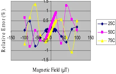
Fig. 7. Sensor output relative error for applied temperature
From Fig. 6 and 7 we can see that absolute error are 0.05V, 0.09V, and 0.118V and relative error are 0.77%, 1.27%, and 1.34% respectively for 25°C, 50°C, and 75°C.
V. CONCLUSION
From this research and the analysis we can obtain the conclusion as follows:
a) Fluxgate sensor’s output voltage stability is influenced by the environment temperature.
b) For increasing the sensor’s response quality, it needs better design of the sensor and signal processing circuit.
REFERENCES
[1] Fraden, J., 1996: Handbook of Modern Sensor. New York, Springer-Verlag New York, Inc.
[2] Ripka, P., 2001: Magnetic Sensor and Magnetometers, Artec House. [3] Ioan, C., H. Chiriac, E.D. Diaconu, A. Moldovanu, E. Moldovanu, C. Macovei, 2002: High-Resolution Fluxgate Sensing Elements Using Co68,25Fe4,5Si12,25B15 Amorphous Material, J. of Optoelectronic and Advanced Materials, Vol. 4 No. 2. pp. 319-324.
[4] Kaluza, F., Angelika Gruger, Heinrich Gruger, 2003: New and Future Applications pf Flxgate Sensors, Sensor and Actuator, Vol. 106, pp. 48-51. [5] Ando, B., S. Baglio, V. Caruso, V. Sacco, A. Bulsara: 2006: Multilayer Based Technology to Build RTD Fluxgate Magnetometer, J. Sensor & Transducer Magazine, (S&T e-Digest), Vol 65 pp. 509-514.
[6] Carr, C., P. Brown, T.L. Zhang, O. Aydogar, W. Magnes, U.Auster, A. Balogh, T. Beek, H. Eicherberger, K.H. Fornacon, E. Georgerscu, J. Gloag, H., Liao, M. Ludlam, R. Nakamura, H. O’Brien, T. Oddy, I. Richter, 2006: The Star Magnetic Field Investigation: Overview of Instrument Performance and Initial Result, J. Advances in Spce Research, 38, pp. 1828-1833.
[7] Caruso, M.J, Tamara B., 1998: A New Perspective on Magnetic Field Sensing, Sensor Magazine, Magnetic Sensor, www.ssec.honeywell.com. 2007. [8] W. Goepel, J. Hesse, J. N. Zemel, Sensors, A Comprehensive Survey, Vol. 5, Magnetic Sensors, VCH, Weinheim, 1989
[9] Smith, C.H, Robert Scheneider, 1998: A New Perspective on Magnetic Field Sensing, Sensor Magnazine, Magnetic Sensor, www.nve.com. 2007. [10] Li, X.P., J. Fan, J. Ding, H. Chiriac, X.B. Qian, J.B. Yi, 2006b: A Design of Orthogonal Fluxgate Sensor, J. of Apllied Physics, Vol 99, pp. 08B33131-08B33133.
[11] Djamal, M., R. N. Setiadi, 2006: Pengukuran Medan Magnet Lemah Menggunakan Sensor Magnetik Fluxgate dengan Satu Koil Pick-Up, Jurnal Proceedings ITB.
[12] Limansyah, I., M. Djamal, 2003a: AC External Magnetic Field Detection with Fluxgate Magnetometer, Seminar Instrumentasi Berbasis Fisika (SIBF 2003), 12-13 Juni, Bandung
[13] Acuna, M. H., Pellerin, Ch. J., “A Miniatur Two-Axis Fluxgate magnetometer”, IEEE Trans. Geisci. Electr. GE-7, No. 4 (1969) 252-260. [14] Grueger, H., Gottfried-Gottfried, R., “CMOS Integrated Two Axes Magnetic Field Sensors – Miniaturized Low Cost System With Large Temperature Range”, Fraunhofer Institute for Microelectronic Circuits and Systems IMS (2000), p. 35-38
[15] Aschenbrenner, H. et al, “Eine Anordnung zur Registrierung rascher magnetischer Stoerungen”, Hochfrequenztechnik und Elektroakustik 47, No. 6 (1936) 117-181.
[16] Greiner, I., “Feldmessungen nach dem Oberwellenverfahren, Sieb- und Differenzsonden”, Nachrichtentechnik 10, No. 3 (1960) 123-126.
[17] Djamal, M., 2007: Sensor Magnetik Fluxgate dan Aplkasinya untuk Pengukuran Kuat Arus , J. Sains dan Teknologi Nuklir Indonesia, III, pp. 51-69 [18] Baschirotto, A. E. Dallago, P. Malcovati, M. Marchesi, G. Venchi, 2006: Development and Comparative Analysis of Fluxgate Magnetic Sensor Structure in PCB Technology, IEEE Transaction on Magnetics , Vol. 42 No. 6 pp. 1670-1680.
[19] Kerta, W., Einfuhrung in die Geophysic, in BI – Hochshultaschen bücher, Manheim : BI – Wissenschaftsverlag, Vol. 275, 1969, pp. 171 ff.