ISSN: 2278-4861.Volume 2, Issue 5 (Nov. - Dec. 2012), PP 29-35 www.iosrjournals.org
A Magnetic Distance Sensor with High Sensitivity Based on
Double Secondary Coil of Fluxgate
Widyaningrum Indrasari
1, Mitra Djamal
2, Wahyu Srigutomo
2, Ramli
3 1Department of Physics, State University of Jakarta, Indonesia
2Department of Physics, Bandung Institute of Technology, Indonesia 3Department of Physics, State University of Padang, Indonesia
Abstract : A magnetic distance sensor with high sensitivity based on double secondary coil of fluxgate has been investigated and discussed in this paper. Fluxgate sensor element is made using conventional methods, based on double secondary coil design, consists of four primary winding and two secondary windings. Secondary coil is located in the center core and is flanked by the primary coil. Effect of the number of pick-up coil on sensitivity and sensor work area were investigated by making four pick-up coil configurations with a fixed number of winding excitation. Sensor sensitivity increased significantly with increasing the number of pick-up windings while the coil excitation is fixed. Characterization of distance sensor is using permanent magnets as magnetic source and flux meter as calibrators, by changing the position of the magnet on flux meter. We found that the output voltage and sensitivity of sensor is inversely proportional to the distance range of the sensor. The relative error of sensor measurement to the measurement results of flux meter has a maximum value of 3.97 %. . For distance sensor, we found that the maximum relative error of measurement is 4.77 %.
Keywords – Distance sensor, fluxgate, magnetic sensor, secondary coil, sensitivity
I. Introduction
Magnetic sensor is widely used for study of magnetic materials, space research, navigation systems, positioning objects, etc. Fluxgate sensor is one of magnetic sensor that still attracts the attention of many researchers. This is caused by advantages of fluxgate sensor which is more sensitive [1,2,3] and more precise [4]. Fluxgate has been used as magnetic sensors since the 1930's [5]. Nowadays, fluxgate sensors have been developed as an instrument of geophysics [6], detection of ferromagnetic objects [7], the space instruments [8], the instrument bio-magnetic [9], magnetic tracker [10] and magnetic distance sensors [11].
Measurement of the position and displacement of objects is very important for many applications, such as process feedback control, performance evaluation, transport traffic control, robotics, and security systems. However, most of the sensors for position measurement have drawbacks such as complicated structure, high cost, and low accuracy. To achieve a position measurement with high accuracy and low cost, many new technologies have been applied [12, 13]. Fluxgate sensor seems to be one of the best candidates to meet the criteria of low cost, simple structure and high sensitivity.
Fluxgate sensor can measure DC and AC magnetic fields in the range 100pT – 1mT. Fluxgate sensor has a very high sensitivity, small size, small power requirements, and has high temperature stability [14]. The sensitivity of the fluxgate sensor depends on the number of sensor windings and permeability of the core material [15]. Although the use of the core material will cause demagnetization factors that influence the magnitude of the voltage sensor. Generally, the core material that used is a material that can be magnetized with high permeability (μr ~ 105), low coercivity, and saturation magnetic induction at 0,55 T [5].
Several manufacturing technologies have been used by researchers to optimize fluxgate sensors, among others; using conventional technologies, PCB technology, micro technology and hybrid technology. The use of different technologies will make a difference in sensors shape, the core material, core cultivation technology, and the power of the sensor, such as sensitivity, accuracy, and resolution of the sensor. In this paper, we propose the use of fluxgate sensor with double secondary coil using conventional technology as a distance sensor.
II. Overview
2.1. Basics Principle of Fluxgate Sensor
A fluxgate sensor is designed to have an output proportional to the magnetic field being sensed. Fluxgate sensor works by comparing the measured magnetic field Bext with reference magnetic field Bref.
Fig. 1. The simple form of the magnetic fluxgate sensor
Excitation coils used to generate the magnetic field due to the electric field in the solenoid (Faraday's law), whereas pick-up coil serves to capture the magnetic field changes caused by external magnetic field. Pick-up coil will evaluate the sPick-uperposition result of the reference magnetic field Bref and the measured magnetic field
Bext, than produce e.m.f induction. The output voltage (Vout) in the pick-up coil is the rate of change of the
magnetic flux in the core. Based on Faraday's law, amplitude of output voltage induced is written as:
out
where N is the number of secondary coil windings and A is the cross-section area of the sensor core pieces. So the output voltage on the second harmonization of secondary coils is [16]:
2
where hext is the external magnetic field, and K is a constant. It appears that the second harmonic output voltage is proportional to the intensity of measured magnetic field, B0.
2.2. Distance Sensor Based on Fluxgate
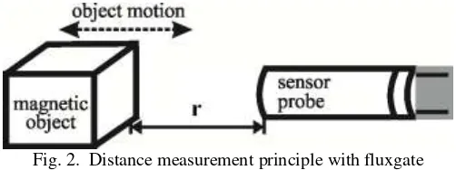
Development fluxgate as distance sensors based on the ability to detect changes in the magnetic field. Changes in the magnetic field are due to changes in the distance between the probe fluxgate with the object being measured. Fluxgate can only detect the magnetic material. Magnetic materials derived from a permanent magnet or a ferromagnetic material. To apply as distance sensors then the object is placed at a certain distance from the fluxgate as shown in Fig. 2.
Fig. 2. Distance measurement principle with fluxgate
If the object is moving toward or away from the sensor, then the magnetic field around the equilibrium point will experience a change in magnetic flux (Φ). Changes in the magnetic flux of the sensor depend on the
If the intensity of the magnetic field of the source is B, then the magnetic field detected by a sensor at a distance
r is:
According to (5), decrease in the magnetic field is proportional to 1/r3 [11], whereas the sensor output voltage is proportional to the external field. So it can also be stated that the output voltage corresponding to the relationship between the external field with distance.
III. Experiment
on sensitivity and sensor work area were investigated by making four pick-up coil configurations with a fixed number of winding excitation. Conversely, to investigate the effect of changes in the excitation coil on sensitivity and the sensor work made four excitation coil configurations with remains winding number pick-up. The ferromagnetic core used vitrovac 6025 Z (Vacuumschmelze) with a width of 1.5 mm and thick 0.025 mm. Core length varied and adjusted to the length of each sensor. The number of the core layer is used as one layer, since greater number of the core layer, the greater the demagnetization factor [17].
Fig.3. Design of fluxgate elements with doube secondary coil (adopted from [18])
Characterization of the fluxgate sensors performed inside a Faraday room, using the calibration coil as an external magnetic source of the sensor, with a current of 80 mA to - 80 mA flow to this coil. While for measurement of distance used a permanent magnet as the source magnetic field and a flux meter as a reference.
IV. Result and Discussion
4.1.Effect of Number of Pick-Up and Excitations Winding to the Sensor Sensitivity
The response of sensor output voltage due to an applied external magnetic field, for some variety number pick-up coils and excitation coils are depicted in Fig. 4. The range of linear work area of sensors for each sensor is different, depends on the number of pick-up coil winding and the length of sensor core. The increasing of the number of pick-up coil windings and the length of sensor core will decrease the number of demagnetization factor [19], as expressed in (6) and (7).
1 1 r A
r
D
(6)
1 core coil coil A
coil core
L L A
L A
(7)
where D and µr is demagnetization factor and relative permeability, Lcore and Lcoil is inductance of pick-up coil with core and without core. While Acore and Acoil , is cross section area of coil with core and without core. The result of demagnetization factor is listed in Table 1. The decreasing of the number of demagnetization factor will reduce the current needed to reach saturation sensor, consequently the sensor has a shorter linear work area.
Fig. 4. Characterization curve of sensors in the work area ± 40μT (a) pick-up coil varies; 10, 30, 40, 60, fixed excitation coil of 20 (b) excitation coil varies: 20, 30, 40, 50, and fixed pick-up coil of 60.
than others. This is due to the sensor has the highest pick-up coil number among them. As a result, the e.m.f produced larger than others, so quickly experience saturation. Whereas in Fig 4b, sensors with number of excitation coil was varies and the number of pick-up coils remains constant, seen having the similar saturation. As the numbers of pick-up coils are fixed, then the number of demagnetization factor is the same.
Sensitivity (S) is the ratio of the change in the output signal to the respective change in the input signal of
The measured sensitivity and relative error of each sensor was taken in the work area 8 μT as shown in Table 1. The sensitivity of the sensor is proportional to the number of pick-up windings. Sensor sensitivity increased significantly with increasing the number of pick-up windings while the coil excitation is fixed (Table 1, No. I-IV). This occurs because the increasing of the windings number of the pick up coil will improve the sensor ability to capture the magnetic flux of the core material.
Conversely, for a number of excitation winding varies while the number of pick-up coils fixed (Table 1, No. IV-VII), range increased of sensor sensitivity is only 90 mV/μT. Sensitivity of the sensor increases due to the increasing number of primary windings will increase the number of the excitation field, so the amount of magnetic flux captured by the secondary coil will increase.
Table 1. Sensitivity, relative errors and demagnetization factor of fluxgate sensor
Sensor No.
Through a third-order polynomial approximation, relative error sensors can be reduced, except in excitation coil number 20 and pick-up coils number 10, as seen in Table 1 above. This is due to range of the linear area of the
sensor was much quite in the amount of ± 40μT (Figure 4a (sensor I)).
4.2.Characterization of Distance Sensor
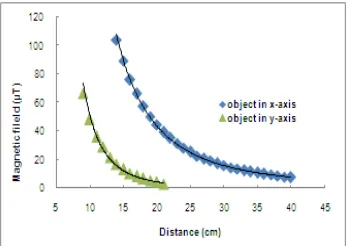
Characterization of initial distance is using permanent magnets as magnetic source and flux meter as calibrators, by changing the position of the magnet on flux meter. Given magnetic field from the south pole of the bar magnet is firstly placed in the direction of the x-axis (parallel to the flux meter), secondly it placed in the direction of the y-axis (parallel to the earth’s magnetic field). The responses of the flux meter output as the function of object position are shown in Fig. 5. Difference of the flux meter output response to the object on the x-axis and the y-axis due to the influence of the earth's magnetic field, especially on the y-axis. In the DC-field, the using of permanent magnet as a magnetic marker is quite difficult to be distinguished from the earth’s field, that cause gross error in larger distances [11].
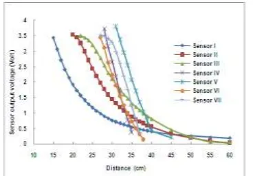
The response of the sensor output voltage to a magnetic field, in the x-axis, for several variations of the number of pick-up windings and excitation has been depicted in Fig. 6. The output voltage and sensitivity of sensor is inversely proportional to the distance range of the sensor, due to the limited of sensor linear work area. Sensor I which has lowest sensitivity capable of detecting a greater magnetic field, due to the linear work area of the sensor is larger than other sensors (± 115μT). This sensor is able to detect changes in the distance of 2.5 - 38 mV/mm. Meanwhile, sensor VII that has the highest sensitivity and the shortest linear work area has the shortest distance range 30-45 cm. When the external magnetic field have given to a sensor with higher sensitivity, this sensor will be easier to reach saturation, so the ability of the sensor to detect external magnetic field is more limited. Distance changes that can be detected sensor VII is at 3.8 - 42.2 mV/mm.
Fig.6. Characterization distance curves using fluxgate sensor (sensor placed in x- axis parallel to the source of magnetic field).
Based on the results in Fig. 5, and then performed characterization distances on y-axis using sensor I. These results are compared with the results of the characterization by flux meter. Thus, it can be obtained linear equation expressing the relation between the sensor output voltages with the field measured by flux meter, i.e.
Bx = 28.10Vx - 4.785 (9)
By = 36.85Vy - 8.127 (10)
where Vx and Vy is the output voltage of the sensor on the x and y-axis. Meanwhile, Bx and By is the magnetic
field intensity measured by flux meter on the x and y-axis. Through (9) and (10) obtained conversion curves of intensity magnetic field to the distance of sensor for sensor I (Fig. 7a). Relative error of sensor has a maximum value for Bx measurement was 3.8% at the distance of 0.18 m, meanwhile for By measurement was 3.97 % at the
distance of 0.09 m (Fig. 7b).
Fig. 7. (a) The curve of the position versus magnetic field output of sensor I in x and y-axis. (b).The curve of relative error of the sensor to the flux meter
Based on curve in the Fig. 7 can be obtained equations expressing the relation of the magnetic field intensity to the objects position in the x and y-axis, i.e.
Bx = 0.788 x-2.5 (11)
By = 0.022 y-3.3 (12)
where x and y is the distance of object to the sensor on the x and y-axis, in meters. Meanwhile, Bx and By is the
intensity of magnetic field measured by sensor in the x and y-axis.
4.3.Application of Sensor for Displacement Measurement
Fig. 8. Scheme of displacement measurement, r is the distance of the object to the sensor, while is an angle of the object to the-x axis
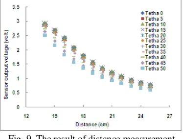
Fig. 9. The result of distance measurement
Measurements were also performed using flux meter, as the reference data of magnetic field intensity at each position. Based on sensor output data on Fig. 9 and measurement data of magnetic field intensity using a flux meter, the relationship between these parameters can be determined, i.e.
1.73
B
V (13)0.105 31.22
(14)
where V is the output voltage of the sensor on the r distance, and B is the magnetic field intensity measured by flux meter. Meanwhile, is an angle of the object to the-x axis (00 500). Through (13) obtained conversion
curves of intensity magnetic field to the distance of sensor as a function of r and, i.e. a
r
B kr (15)
0.776 cos 0.207
k (16)
0.328 2.949
a cos (17)
where r is the distance of the object to the sensor probe, in meter (m), B is the magnetic field intensity measured by sensor at position (r,) to sensor. While k and a are the coefficients rely on the angle between the object and the sensor (). The result of Br calculations is shown in Fig. 10a. The magnetic field of the sensor decreases with increasing and r of the object. The maximum relative error of calculation is 4.33 % to the flux meter, as shown in Fig. 10b.
After calibration, the sensor was tested to measure the arbitrary position of objects. The sensor output voltage of the distance measurement then was converted to magnetic field intensity according to (13). The result of calculation is compare to the Br calculation. The maximum relative error of calculation is 4.77 % at position (22 cm, 43.150) to the Br calculation.
V. Conclusion
An alternative method based on a magnetic fluxgate sensor with double secondary coil has been developed for the distance measurement. This method based on the ability of fluxgate to detect changes in the magnetic field. Changes in the magnetic field are due to changes in the distance between the probe fluxgate sensors with the object being measured. The sensitivity of the sensor is proportional to the number of pick-up windings. Sensor sensitivity increased significantly with increasing the number of pick-up windings while the coil excitation is fixed. The output voltage and sensitivity of sensor is inversely proportional to the distance range of the sensor, due to the limited of sensor linear work area. In application of sensor to displacement mesurement, have been found that the magnetic field of the sensor decreases with increasing and r of the object. The maximum relative error of measurement is 4.77 %. These results indicate that the fluxgate sensor with dual secondary coil that have been developed can be used as a magnetic distance sensor. Furthermore, we will develop these sensors as receiver in the CSEM (controlled source electromagnetic) device for subsurface resistivity mapping.
Acknowledgment
The authors would like to thank Directorate of Research and Community Service, the Ministry of Education and Culture of the Republic of Indonesia that has funded this research through Competitive Grant under Contract No. 06/SP2H/Dit.Litabnas/HB/LP-UNJ/II/2012.
References
[1] F. Primdahl, The fluxgate magnetometer, J.Phys. E: Sci. Instrum. 12, 1979, 241-253. [2] J. Lenz, A review of magnetic sensors, Proc. IEEE78 (6), 1990, 973-989.
[3] M. Janosek and P. Ripka, PCB sensors in fluxgate magnetometer with controlled excitation, Sensors and Actuators A151, 2009, 141–144.
[4] P. Ripka, Magnetic sensors and magnetometers (Artech; London, 2001). [5] P. Ripka, Review of fluxgate sensors, Sensors and Actuators A33, 1992, 129-141,.
[6] W. Srigutomo, T. Kagiyama, W. Kanda, H. Munekane, T. Hashimoto, Y. Tanaka, H. Utada, M. Utsugi, Resistivity structure of Unzen Volcano derived from time domain electromagnetik (TDEM) survey, Journal of Volcanology and Geothermal Research175, 2008, 231–240.
[7] H.S. Park, J.S.Hwang, W.Y.Choi, D.S.Shima, K.W.Na, and S.O.Choi, Development of micro-fluxgate sensors with electroplated magnetic cores for electronic compass, Sensors and Actuators A,114, 2004, 224-229.
[8] M.H. Acuna, Space-based magentometers, Rev. Sci. Instrum. 73 (11). 2002, 3717–3736.
[9] P.Ripka and P. Navratil, Fluxgate sensor for magnetopneumometry, Sensors and Actuators A,60, 1997, 76-79. [10] P. Ripka and A. Zikmund, Magnetic Tracker with High Precision, Procedia Engineering, 25 ,2011, 1617 – 1620.
[11] A. Zikmund and P. Ripka, A Magnetic Distance Sensor with High Precision, Sensors and Actuators A,186, 2012, 137 – 142.
[12] X. Lu, W. Li, and Y. Lin, Development of wide range displacement sensors based on polarized light detecting technology, Optica Applicata, Vol. XLI, No. 1, 2011, 97-108.
[13] W. Li, X. Lu and Y. Lin, Novel Absolute Displacement Sensor with Wide Range Based on Malus Law, Sensors, 9, 2009, 10411-1042.
[14] Yulkifli, Pengembangan Elemen Fluxgate dan Penggunaannya untuk sensor –sensor berbasis magnetic dan proksimiti, doctoral diss., Bandung Institute of Technology, Bandung, Indonesia, 2010.
[15] X.P. Li, J. Fan, Ding, X.B. Qian., Multi-core Orthogonal Fluxgate Sensor, J. Magnetism and Magnetic Material, 300, 2006, 98-103. [16] W. Göpel, J. Hesse, J. N. Zemel, Sensors: A Comprehensive surveyVol (VCH Verlagsgesellschaft mbH, Berlin, 1989).
[17] Widyaningrum Indrasari, Umiatin, Mitra Djamal, Karakterisasi Sensor Magenetik Fluxgate Kumparan Sekunder Ganda Menggunakan Elemen Sensor Multi-core (core : Vitrovacs 6025Z l = 1.5 mm), Proc. Seminar Fisika Nasional, Jakarta, 2012. [18] M. Djamal, E. Sanjaya, Yulkifli and Ramli, Development of Fluxgae Sensors and Its Applications, Proc. 2011 International


