A SENSOR AIDED H.264/AVC VIDEO ENCODER FOR AERIAL VIDEO SEQUENCES
WITH IN THE LOOP METADATA CORRECTION
L. Cicalaa, C. V. Angelinoa∗
, G. Ruattab, E. Baccaglinib, N. Raimondob a
CIRA, the Italian Aerospace Research Centre, 81043 Capua, Italy - (l.cicala, c.angelino)@cira.it bIstituto Superiore Mario Boella, Torino, Italy - (ruatta, baccaglini, raimondo)@ismb.it
Commission III, WG III/3
KEY WORDS:UAV, sensor aided video coding, metadata correction, h.264, x264, vision aided navigation, sensor fusion
ABSTRACT:
Unmanned Aerial Vehicles (UAVs) are often employed to collect high resolution images in order to perform image mosaicking and/or 3D reconstruction. Images are usually stored on board and then processed with on-ground desktop software. In such a way the computational load, and hence the power consumption, is moved on ground, leaving on board only the task of storing data. Such an approach is important in the case of small multi-rotorcraft UAVs because of their low endurance due to the short battery life. Images can be stored on board with either still image or video data compression. Still image system are preferred when low frame rates are involved, because video coding systems are based on motion estimation and compensation algorithms which fail when the motion vectors are significantly long and when the overlapping between subsequent frames is very small. In this scenario, UAVs attitude and position metadata from the Inertial Navigation System (INS) can be employed to estimate global motion parameters without video analysis. A low complexity image analysis can be still performed in order to refine the motion field estimated using only the metadata. In this work, we propose to use this refinement step in order to improve the position and attitude estimation produced by the navigation system in order to maximize the encoder performance. Experiments are performed on both simulated and real world video sequences.
1. INTRODUCTION
Nowadays, collection of data is the most important purpose of any Unmanned Aerial Vehicles (UAVs) (Chen et al., 2011). In military applications, long range UAVs can penetrate areas and locations that manned expeditions cannot effort without excep-tional risks. Often this task is achieved using a set of on-board HD digital video cameras. The STANAG 4609 standard (NATO, 2009) is currently employed in NATO military UAV applications and adopts MPEG-2 and H.264/AVC standards for both Standard (SD) and High Definition (HD) motion imagery coding. How-ever, these standards have been developed for general purpose video encoding and do not exploit the typical features of aerial video sequences. For instance, during the completion of mission, it is often required for UAVs to operate BLOS (Behind Line of Sight), a condition in which the direct communication between the vehicle and the ground control station is unfeasible. In this scenario the motion imagery acquired from payload sensors must be uploaded on a satellite data-link whose bandwidth is usually limited. It is then unlikely to achieve a high frame rate acquisi-tion even because addiacquisi-tional data gathered by the other payload sensors share the same data-link and further reduce the band-width available to the video stream. In civilian application mini-UAVs,i.e., small remote piloted multirotorcrafts, are used in line of sight, often to acquire high resolution images for mosaicing and/or 3D reconstruction. During the mission, these high resolu-tion data are stored on-board, while only the video coming from the first person view camera is sent on-ground to the remote pilot. In this situation the main mission constraint is the duration of the battery that supplies the vehicle.
In both the mentioned situations, it can be desirable to optimize the available resources (bandwidth, power supply) in order to improve the mission performance (more data, more flight time). When high frame rate videos are not a desiderata of the mission,
∗
Corresponding author
one solution can be the reduction of the acquisition frame rate. In such a scenario, the video sequences are sent/stored at few frames per second (fps) and hence the overlap between two con-secutive frames is lower than standard video streams. Usually at low frame rates the commercial video encorders fail in perform-ing a good motion estimation/compensation, due to the length of the motion vectors and to the prospective changes among frames that make hard the motion vector prediction. In such situations a still image encoder can be more or equally performing.
MVs. Both approaches guarantee the generation of a standard-compliant H.264/AVC bitstream, thus no changes at the decoder side are required.
In this paper, as a natural continuations of the studies reported in (Angelino et al., 2012, Angelino et al., 2013b) and (Angelino et al., 2013a), we propose a sensor aided video encoder to be used at high resolution and low frame rates on aerial video sequences. The proposed encoder is obtained modifying the open source implementation of h.264/AVC video coding standard (ISO/IEC, 2006) x264 (Merritt and Rahul, 2006) and fully compliant with h.264. As opposed to the previous works, here the problems of video coding and of the needed metadata correction are tackled in the same integrated design. This paper is focused on the im-provements in terms of rate-distortion performance. Moreover, further aspects about a sensor aided encoder design, unpublished results and considerations are reported.
The remainder of this paper is organized as follows. Section 2. introduces the proposed sensor aided coding scheme with in the loop metadata correction. Section 3. presents in details the mod-ifications to the original x264 open source code and reports a comparison of the computational complexity of the proposed ap-proach with the original scheme. Section 4. describes how to improve the navigation data using the optical flow calculated by the proposed video encoder.In Section 5. experimental results are presented and in Section 6. conclusions and future work are dis-cussed.
2. SENSOR AIDED VIDEO CODING
2.1 Encoding scheme
The h.264 standard design follows the so-called block based hy-brid video coding approach in which each coded picture is rep-resented in block-shaped units. The approach is hybrid because inter-picture prediction is used to exploit temporal statistical de-pendencies and transform coding of the prediction residual is the performed to exploit spatial statistical dependencies. The blocks can be predicted in Intra (from blocks of another frame) or In-ter mode (from blocks of the same frame). The InIn-ter prediction can be of type Predicted (from a single frame), or of type Bi-predicted (from two frames, one belonging to the previously ac-quired frames, the other belonging to the successively acac-quired frames). If type Bi-predicted frames are used, the encoder must wait some frames before to encode the current frame, introduc-ing a delay. For every Group Of Pictures (GOP) to encode, the sequence of I (Intra), P (Predicted) and B (Bi-Predicted) frames is determined by a GOP decision algorithm.
The Inter prediction is performed by a ME step, in witch the translational motion vector is estimated for every block of the video frame to encode, followed by a motion compensation pro-cess, in witch the block of the previously encoded (and decoded) video frame is translated on the current block position. In (An-gelino et al., 2013b) the authors propose to modify a well known open source implementation of a standard h.264 encoder, x264, which uses the metadata provided by the navigation system of the UAV in order to accurately predict the MVs, at low frame rates also. Experimental results showed that in such way both better qualityvsbitrate tradeoffs and lower computational complexity can be reached.
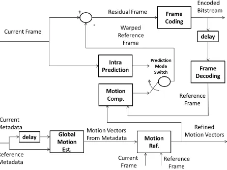
In this work we present a similar encoder, whose structure is shown in Figure 1. A common h.264 encoding scheme is modi-fied in order to take in account of metadata (position and orienta-tion) coming from the navigation system of the UAV. The camera is supposed to be internally and externally calibrated with respect
Figure 1: Sensor aided video encoder scheme.
to the navigation system. A Global Motion Estimation (GME) is performed using metadata and a rough planar representation of the overflight scene (i.e., supposing the ground an horizon-tal plane and using an altimeter to determine the distance of the aerial platform from the ground). A further MV refinement is performed by block matching, as proposed in the original version of x264, but starting from a more accurate initial estimate of the MVs, as provided by the GM estimation module.
Further, in addition to the scheme presented in the cited work, the proposed solution uses the estimated motion field as opti-cal flow estimation for a state-of-the-art camera egomotion al-gorithm based on RANSAC homography model estimation and algebraic motion data extraction. The camera egomotion is used in loop with an Unscented Kalman Filter (UKF) in order to re-fine the position and orientation data provided by the navigation system. Such use of the motion field will be discussed in the Subsection 4..
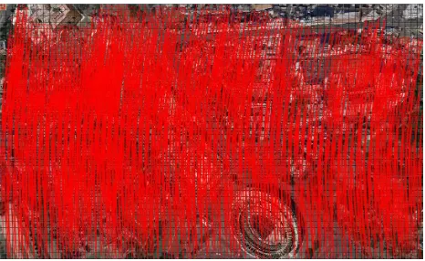
Figures 2 and 3 show a situation in which the ME algorithm of x264 fails while the proposed ME process, initialized with the sensor based GME, performs with success. The vectors in over-lay represent the motion vectors found by the ME process. When an appropriate MV cannot be estimated, Intra prediction is per-formed instead.
Figure 2: An example of failure of the motion estimation at low frame rates (0.5 fps).
2.2 Sensor aided Global Motion estimation
Figure 3: An example of correct motion estimation initialized by a sensor aided global motion estimation. The analyzed video is the same of Figure 2.
metadata in order to initialize the motion field (Global Motion estimation).
We first introduce some notation. Matrices are denoted by capital italics. Vectors are denoted by bold fonts either capital or small. A three-dimensional column vector is specified by(s1, s2, s3)T.
A vector is sometimes regarded as a column matrix. So vector operation such as cross product (×) and matrix operations such as matrix multiplication are applied to three-dimensional vectors. Matrix operations precede vector operations. 0denotes a zero vector. For a matrixA= [aij],||A||denotes the Euclidean norm
of the matrix,i.e.,||[aij]||=
qP
ija2ij. We define a mapping
[·]×from a three-dimensional vector to a 3 by 3 matrix:
h
(x1, x2, x3)T
i
×
=
0 −x3 0
x3 0 −x1
−x2 x1 0
. (1)
Using this mapping, we can express cross operation of two vec-tors by the matrix multiplication of a 3 by 3 matrix and a column matrix:
X×Y = [X]×Y. (2)
The reference systems, in which the coordinates of the vectorx are expressed, is reported as superscribe on the upper-left corner ofxwith the notationxs.
The reference systems considered in the paper are the following:
i inertial system;
e the ECEF (Earth Cenetered Earth Fixed) system;
n the NED (North East Down) system, tangent to the earth ellip-soid, at a reference Latitude and Longitude(Lat0,Lat0);
b the ”body” system as seen by the IMU (Inertial Measurement Unit);
c the camera system, with fixed orientation with respect the IMU.
The default coordinate system in which the UAV position,i.e. (Lat, Lon, Alt) of the vehicle center of mass, is given is the ECEF system. Ce
nis the reference change matrix from NED to ECEF.
The attitude and heading of the vehicle is given asCn b(φ, θ, ψ)
whereCn
b is the reference change matrix associated with the roll
(φ), pitch (θ), and yaw (ψ) angles. In general, the camera stan-dard reference system might be rotated with respect to the body reference system. Thus, the transformation from the camera ref-erence to ECEF is given by
Cce=Cne(Lat, Lon)Cbn(φ, θ, ψ)Ccb (3)
whereCb
c represents the constant reference change matrix from
camera systemcto body unit systemb.
Let us consider a 2-D planeΠin 3-D space. Consider two images taken by the camera at different time. The equation linking two image pointsp′
andpwhich are the projection of the same point ofΠis:
p′
≃HΠp, (4)
wherep′
= [u′
, v′
,1]T
andp= [u, v,1]T
are the (normalized) homogeneous coordinates in the second and the first camera ref-erence frame respectively and the symbol≃means that equality is up to a scale factor. We call the matrix
HΠ=
Cc2
c1+
rc2 21NT
d
(5)
the planar homography matrix induced by the planeΠ. It contains the information about the camera movement ([Cc2
c1, rc212]) ant the
scene structure (the normal to the planeN, and the distanced).
We suppose that the scene structure is known, supposingNn=
(0,0,−1)and using an altimeter to determine the distancedof the aerial platform from the ground. Here[Cc2
c1, rc212]represents
the rigid transformation (rotation and translation) which brings points (i. e. transforms coordinates) from the camera 1 to the camera 2 standard reference system.
The coordinates change equation is given by
xc2=Cc2 c1x
c1
+rc2
21 (6)
wherexck
represent the coordinates in the camerakstandard ref-erence system.
The translation vector between the two camera centerrs
12=Os2−
Os1expressed in a generic reference systemsis equal to−C2src212.
The matrixCc2
c1 contains in it different contributions:
1. the rotation of the camera by the pan-tilt unit;
2. changes in the vehicle attitude and heading;
3. rotation between the two NED systems (int2andt1).
Indeed it can be also expressed as
Cc2 c1 =C
c2 e C
e c1 =C
e c2
T
Cce1 (7)
Cc2 c1 =C
c2 b2C
b2 n2 C
n2
e C
e n1
| {z }
≈I
Cn1 b1 C
b1
c1 (8)
In the above equation we supposed (Lat,Lon) did not change a lot between two consecutive frames, hence the identity approxima-tion. This also means that the two NED reference systems (i.e., corresponding ton1andn2) can be thought to be coincident up
to a translation. The eq.(8) then reads as
Cc2 c1 ≈C
c2 b2C
b2 n2C
n1 b1 C
b1
c1. (9)
Therefore, supposing a fixed camera orientation with respect to the body, the functional dependency is only in the rotation of the body,i.e.in the change of the vehicle attitude and heading,
Cb2 b1 ≈C
b2 n2C
n1
b1 ≈R(dφ, dθ, dψ) =Rx(dφ)Ry(dθ)Rz(dψ)
(10)
wheredφ=φ2−φ1, dθ=θ2−θ1anddψ=ψ2−ψ1.
The notationRa(α) denotes the matrix describing the rotation
alongaaxis of angleα.
3. X264 MODIFICATIONS FOR MOTION DATA EXTRACTION
This section presents the changes made to the x264 encoder (core 142) in order to allow the extraction of the motion data computed during the compression procedure. The modifications do not alter the result video bitstream and the output is still an H.264/AVC compliant stream. A brief preliminary discussion on the x264 library (VideoLan, 2014) is reported followed by the proposed modifications.
The encoder consists of three main stages: the lookahead block, which is responsible, on the basis of user-selected parameters and temporally neighboring frames, to decide each frames type (In-tra, Predicted or Bi-predicted) and the proper quantization step; the analysis block, which analyses each macroblock (MB) within the frame to select the more convenient prediction type (Inter or Intra) and computes all the information required for motion compensation; the coding block, which writes in the output bit-stream the information related to each MB. All the motion in-formation related to the motion compensation of each MB (such as partitions, MVs and reference frames) is available into the
x264 macroblock analyse function. This function performs an analysis according to the frame type. In the case of I frame, only spatial prediction modes are tested, checking which neigh-bours are available and computing for each mode and for each possible partition a cost. Then, the combination of partition and prediction that maximize the quality and minimize the coding rate is selected. In the case of P and B frames the procedure is simi-lar, but Inter prediction is also tested, computing a MV for each available reference frame. Motion compensation is initially ap-plied to 16x16 MBs and then for each possible partition. The partitions with the minimum cost are selected, each one with its correspondent MV and reference. All these motion data are then copied in a cache structure within the mb structure, which con-tains all the information related to the current MB, and the fol-lowingx264 macroblock encodefunction write them into the bitstream. Within the cache structure, the reference indexes and the MVs are stored in two different integer arrays, i.e. ref and
mv. The bi-dimensional ref array contains the frame reference indexes. The first dimension of the array refers to the reference list, namely L0 for previous reference frames (used for both P and B frames) and L1 for future reference frames (used only by B frames). The second dimension refers to the spatial position of the partition within the MB. Since the minimum partition in H.264/AVC standard is 4x4 then there are 16 different indexes. If a bigger partition is selected by the encoder for that specific MB, all the reference indexes are duplicated. The array mv con-tains the MV of each MB. The first and the second dimension are as before, while the third dimension distinguishes the hori-zontal and vertical component of the MV. Once the encoder has finished encoding a MB, it starts with the following one and all the motion data stored in the mb structure is overwritten. The proposed framework implements at this stage a function whose task is to save all the motion information related to every MB. The preserved parameters are MVs, reference indexes, MB type, partitions and position within the frame.
4. METADATA CORRECTION BY VISION AIDED SENSOR FUSION
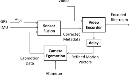
The overall data fusion architecture is sketched in Figure 4, where the sensor fusion block implements the Kalman filtering of the data provided by the Navigation System and the camera tion data from the video processing system. The camera egomo-tion module is based on the homography matrix, which relates homologous points in two different views of the same scene. In this work the correspondences are given by the refined motion vector provided by the encoder.
Figure 4: Metadata improvement by sensor fusion.
From the motion vectors calculated by the encoder, after the mo-tion refinement step, the homography matrix is estimated and then decomposed into his motion and structure parameters. The homography estimation (based on the RANSAC algorithm) and decomposition procedure is behind the scope of this work and will be omitted. The interested reader may refer to (Hartley and Zisserman, 2004) and the reference therein.
be used to calculate the Kalman gain and to update the state pre-diction. Often such a filter has been used to estimate the pose of an UAV. In particular, in this work, we adopt the same solution proposed in (Angelino et al., 2013a).
Angular velocities and linear accelerations provided by the IMU are used in the Kalman prediction step. GPS position and speed as well as camera egomotion parameters are used in the Kalman update step, in order to correct the position and the orientation drift due to the integration of the IMU data. With respect to (An-gelino et al., 2013a) a magnetometer is added, in order to correct the heading.
The state vector includes the position and speed of the aircraft UAV (eq. 11 and 13) in the tangent reference frame, and the rotation matrix from body to tangent reference frame (eq. 14). Moreover, the state vector includes also two variables relative to the delayed aircraft position and the delayed rotation matrix (eq. 12 and 15). The delay is related to the video coding frequency fEN C. The UKF is applied to estimate the state variables. The
input measurements for prediction of state variables are the iner-tial accelerations˜aband the angular speedsΩ˜b
processed by the IMU. Therefore, we have:
Output equations are based on the following measurements:
• GPS antenna positionxeain the ECEF reference frame (eq.
16);
• GPS speedvn
a in the NED reference frame (eq. 17);
• Magnetic headingψµ(eq. 18);
• Camera center position change∆¯xnin the tangent reference frame (eq. 19);
• Camera attitude change∆ ¯Cbrespect to the tangent
refer-ence frame (eq. 20-22).
The state vector equations (11-15) update at thefIM Urate, while
equations (16-18) and (19-22) update respectively atfGP Sand
fEN Crates. When Intra coding is performed, the Kalman update
step based on camera egomotion (eq. 19-22) is skipped.
5. EXPERIMENTAL RESULTS
5.1 Test video sequences
Three different aerial sequences (ISMB/CIRA, 2013) have been encoded and then their motion data have been processed. We con-sidered low frame rate sequences (0.5 - 1 fps) and relative long MVs as this is often the case for UAV acquired high resolution video sequences. The characteristics of the three sequences are reported in Table 1.
Video Seq. FR Res h-FOV Speed Alt [fps] [pix x pix] [deg] [km/h] [m]
Camp Pend. 1 1088x672 60 250 800
Rome 0.5 1088x672 60 250 800
Brezza 1 3000x2000 73.7 2 80
Table 1: Aerial video sequences characteristics.
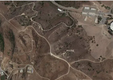
The sequences ”Camp Pendleton” (a snapshot in Figure 5) and ”Rome” (a snapshot in Figure 6) have been generated using Google Earth. In the ”Camp Pendleton” sequence, the overflight region is a military base and the surrounding areas. The area is substan-tially homogeneous and with few details. The ”Rome” sequence refers to a flight over the city of Rome, rich of details. For the simulated sequences the horizontal Field Of View is 60 degrees, the frame resolution is 1088x672 pixels. The flying altitude is 800 m for both the simulated video sequences. The ”Brezza” 7 sequence is part of a video recorded using a real multi-rotorcraft mini-UAV over a rural region poor of details (grass with some trees and only a few of man-made structures). The frame reso-lution is 3000x2000 pixels. The flying altitude (80 m) is much lower than the simulated video sequences. The horizontal FOV is 73.7 degrees.
Ground truth metadata are provided by the image generator for the synthetic video sequences, while for the ”Brezza” sequence, they are estimated from multiple views by a bundle adjustment technique. However, in the experiments a noisy version of these metadata has been generated according to the sensors model de-scribed in (Angelino et al., 2013a). The parameters of the sensors model are extracted by the datasheet of a well known commercial GPS aided Attitude and Heading Reference System commonly employed in aeronautical applications.
Figure 5: A snapshot from the sequence Camp Pendleton, as sim-ulated in Google Earth, with a 1088x672 resolution.
5.2 Data fusion performance
Figure 6: A snapshot from the sequence Roma, as simulated in Google Earth, with a 1088x672 resolution.
Figure 7: A snapshot from the sequence Brezza, with a 3000x2000 resolution.
report the main conclusions on the obtained results. The working conditions of the experiments showed in the Figures 8-10 (i.e. sensors performance) are the same as reported in (Angelino et al., 2013a). The test video sequence is Rome. In the reported experiments, the IMU sampling rate is supposed 100 Hz, the GPS data update is 10 Hz, the camera egomotion processing rate is 5 Hz.
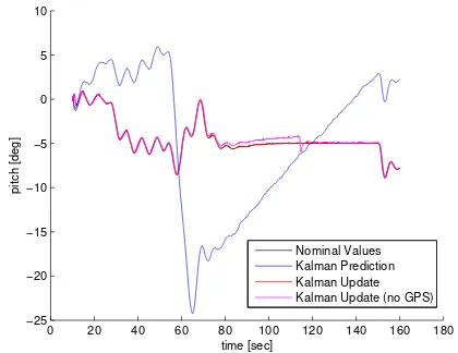
The black line represents the ground truth while the red line rep-resents the estimation performed with the Kalman Filter. In or-der to outline the IMU drift phenomena, the direct integration of the IMU data (Kalman prediction equations only) is represented with a blue line. In this case the corrections performed with the measures coming from GPS, magnetometer and camera (Kalman update equations), are completely skipped.
Figure 8 shows the UAV attitude estimation in terms of pitch an-gle using the UKF. Estimation of Euler anan-gles is independent by GPS measurements. This is due to the choice of installing the GPS antenna at aircraft c.g., in order to highlight the advantages in the application of camera measurements (GPS measurements can be used to estimate attitude only in the presence of a suf-ficient lever arm). In this situation GPS measurements do not provide observability of attitude error.
Figures 9 and 10 show the UAV position and speed estimation along the North direction. As in the attitude estimation, speeds and positions are also estimated with very good performances. The simulation results show that the position and orientation data
can be recovered with high precision with such sensor fusion strategy.
Other experiments have concerned use of the output camera equa-tion alone, in order to simulate GPS outages. The curves are reported in magenta in the same Figures 8-10. Attitude estima-tion, as already explained, is not influenced by GPS. GPS speed, and hence the position, is estimated with degraded performances. However, estimation allows the flight continuation for some time with a reasonable position error. The same sensors model has been used in the experiments concerning video coding, reported in Subsection 5.4.
0 20 40 60 80 100 120 140 160 180
−25 −20 −15 −10 −5 0 5 10
time [sec]
pitch [deg]
Nominal Values Kalman Prediction Kalman Update Kalman Update (no GPS)
Figure 8: Pitch angle estimation (Roma Sequence). Nominal value (black line), Kalman Prediction without GPS (blue line), Kalman Update (red line), Kalman Update without GPS (ma-genta line).
0 20 40 60 80 100 120 140 160 180
41.74 41.76 41.78 41.8 41.82 41.84 41.86 41.88 41.9
time [sec]
lat [deg]
Nominal Values Noisy Data Kalman Prediction Kalman Update Kalman Update (no GPS)
Figure 9: Latitude estimation (Roma Sequence). Nominal value (black line), Kalman Prediction without GPS (blue line), Kalman Update (red line), Kalman Update without GPS (magenta line).
5.3 Encoder settings
0 20 40 60 80 100 120 140 160 180 −200
−150 −100 −50 0 50
time [sec]
Vnorth [m/s]
Nominal Values Noisy Data Kalman Prediction Kalman Update Kalman Update (no GPS)
Figure 10: Linear speed in North direction (Roma Sequence). Nominal value (black line), Kalman Prediction without GPS (blue line), Kalman Update (red line), Kalman Update without GPS (magenta line).
order to reach better encoding quality. These preset options for the proposed modified x264 encoder are labeled in the figures as ”medium” and ”slower”, instead the same configurations in the original x264 encoder are labeled with the prefix ”x264”, and are respectively ”x264 medium” and ”x264 slower”.
The sensor aided encoder often uses only one reference frame in the GOP, because the low overlap among the frames. For this reason, the comparison with the reference x264 encoder with only one reference frame in the GOP is presented. In this case only the ”medium” preset is reported. The corresponding label is ”x264 medium ref1”.
Two other coding option are specifically presented for the pro-posed sensor aided encoder. A first option excludes the refine-ment step of the motion estimation trough video analysis. This option is labeled as ”medium nors”, where the word ”medium” indicates the used preset and the acronym ”nors” is for NO Re-finement Search.
A further option is added in order to force the sensor aided en-coder to perform the motion estimation also when Intra coding is possible. This processing step can be useful in order to produce more accurate motion fields that can be used by the sensor fusion module. These experiments, reported for the preset ”medium”, are labeled as ”medium uem” or ”medium nors uem”, where the latter acronym is for Use Estimated Motion vectors.
5.4 R-D performance improvements
In this section the Rate-Distortion (R-D) performance of the pro-posed sensor aided encoder, using corrected metadata, is com-pared to that of the x264 implementation of h.264. Eight rate-distortion curves are plotted in the Figures 11-13 for each test video sequence. On the x-label the encoding bitrate is reported, while on the y-label the PSNR (Peak Signal to Noise Ratio), that is a commonly used objective video quality measure.
A first observation is that the proposed sensor aided encoder out-performs the reference x264 encoder both with the medium and the slower preset. For example, for the ”Camp Pendleton” video sequence, at 400 kbps, the PSNR of the proposed encoder is 35.41 dB versus 34.76 dB of the reference with the medium preset, and 36.24 dB versus 34.31 dB, with the slower preset. For the se-quence ”Rome”, at the same bitrate of 400 kbps, the PSNR of the sensor aided encoder is 33.93 dB versus 32.74 dB of the reference
with the medium preset, and is 35.18 dB versus 32.50 dB for the slower preset.
The proposed sensor aided encoder has a similar behaviour on real video sequences also. On the sequence ”Brezza”, for exam-ple, at 3250 kbps, the PSNR is 35.12 dB versus 34.48 dB of x264.
It is worth to notice that the reference x264 encoder uses a com-plex GOP analysis in order to optimize the use of the I, P and B frames. The proposed sensor aided implementation instead, at the current stage of development, uses a more simple strategy based on only a I frame per GOP and all P frames (this strategy is reasonable, due to the continuity of the camera motion). For this reason it is more correct to compare the ”medium” curve with the ”x264 medium 1Ref” curve, instead of the ”x264 medium” curve. Comparing these couples of curves, the proposed solution can be further appreciated.
From the figures it is also possible to note that the ”slower” preset has lower quality than ”medium” preset for the reference x264 encoder. This is due to the large number of B-frames selected by the x264 GOP decision algorithm. In the considered scenarios, in which there is low overlap among successive frames, the use of B frames has bad effects on the output quality. The proposed sensor aided implementation, instead, uses the same GOP structure for the two different presets, that is similar to the best option selected by x264.
Further considerations can be made by analyzing only the the sen-sor aided implementations. Indeed, by comparing the ”medium” and ”medium nors” curves, it is clear that the motion search re-finement step, based on video analysis, is essential to reach high rate distortion performance. On the contrary, by comparing the ”medium nors” and ”medium nors uem” curves, it is possible to conclude that a pure motion estimation approach cannot be preferred to a combined strategy, based both on Intra and Inter block prediction, at least in the case in which video analysis is not used to refine the motion vectors. The comparison between the ”medium” and the ”medium uem” curves, however show that, using the video analysis for motion vectors refinement, also don’t considering the Intra option, it is possible to reach a performance near to the combined approach (both Intra and Inter blocks). In the case of Camp Pendleton and Rome, the gap is negligible.
As final remark, we would like to point out that the metadata cor-rection performance is generally very good. Indeed, the standard deviation of the orientation estimation error results less than 0.2 degrees for all video sequences. As a consequence, the encod-ing results are very similar to the ones obtained usencod-ing the ground truth (difference in PSNR lesser than 0.15 dB). For this reason, a comparison of R-D curves between ground truth and corrected metadata is not shown.
6. CONCLUSIONS
Figure 11: R-D Curves for the ”Camp Pendleton” sequence, with a resolution of 1088x672 pixels and a frame rate of 1 fps.
Figure 12: R-D curves for the ”Rome” sequence, with a resolu-tion of 1088x672 pixels and a frame rate of 0.5 fps.
REFERENCES
Angelino, C. V., Baraniello, V. R. and Cicala, L., 2012. Uav position and attitude estimation using imu, gnss and camera. In: Proceeding of the 15th International Conference on Information Fusion (FUSION), Singapore, Singapore, pp. 735–742.
Angelino, C. V., Baraniello, V. R. and Cicala, L., 2013a. High altitude uav navigation using imu, gps and camera. In: Proceed-ings of the 16th International Conference onInformation Fusion (FUSION), Istanbul, Turkey, pp. 647–654.
Angelino, C. V., Cicala, L., De Mizio, M., Leoncini, P., Baccaglini, E., Gavelli, M., Raimondo, N. and Scopigno, R., 2013b. Sensor aided h.264 video encoder for uav applications. In: Proceedings of the 30th Picture Coding Symposium (PCS), pp. 173–176.
Bhaskaranand, M. and Gibson, J., 2015. Global motion assisted low complexity video encoding for uav applications. IEEE Jour-nal of Selected Topics in SigJour-nal Processing 9(1), pp. 139–150.
Chen, X.-l., Zhang, S.-c. and Liu, J., 2011. Design of uav video compression system based on h.264 encoding algorithm. In: Pro-ceedings of the 1st International Conference on Electronic and
Figure 13: R-D curves for the ”Brezza” sequence, with a resolu-tion of 3000x2000 pixels and a frame rate of 1 fps.
Mechanical Engineering and Information Technology (EMEIT), Vol. 5, Harbin, China, pp. 2619–2622.
Gong, J., Zheng, C., Tian, J. and Wu, D., 2010. An image-sequence compressing algorithm based on homography transfor-mation for unmanned aerial vehicle. In: Proceedings of the 1st International Symposium on Intelligence Information Processing and Trusted Computing (IPTC), Huanggang, China, pp. 37–40. Hartley, R. I. and Zisserman, A., 2004. Multiple View Geometry in Computer Vision. Second edn, Cambridge University Press, ISBN: 0521540518.
ISMB/CIRA, 2013. Test sequences [online] available at: http://www.ismb.it/mise cira.
ISO/IEC, 2006. ISO/IEC International Standard 14496–10, In-formation Technology Coding of Audio-Visual Objects Part 10: Advanced Video Coding. Third edn, ISO/IEC.
Julier, S. J. and Uhlmann, J. K., 2004. Unscented filtering and nonlinear estimation. Proceedings of the IEEE 92(3), pp. 401– 422.
Merritt, L. and Rahul, V., 2006. X264: A high performance h.264/avc encoder [online] available at:
http://neuron2.net/library/avc/overview x264 v8 5.pdf.
Morimoto, C., Burlina, P. and Chellappa, R., 1997. Video cod-ing uscod-ing hybrid motion compensation. In: Proceedcod-ings of the 4th International Conference on Image Processing (ICIP), Vol. 1, Santa Barbara, California, USA, pp. 89–92.
NATO, 2009. Stanag 4609, nato digital mo-tion imagery format [online] available at http://www.nato.int/structur/ac/224/standard/4609/4609-documents/4609eed03.pdf.
Soares, P. H. F. T. and Pinho, M. d. S., 2013. Video compression for uav applications using a global motion estimation in the h.264 standard. In: Proceedings of the 6th International Workshop on Telecommunications, Vol. 1, Santa Rita do Sapuca`ı, Brazil. Steinbach, E., Wiegand, T. and Girod, B., 1999. Using multiple global motion models for improved block-based video coding. In: Proceedings of the 6th International Conference on Image Processing (ICIP), Vol. 2, Kobe, Japan, pp. 56–60.
Van Der Merwe, R. and Wan, E., 2003. Sigma-point kalman fil-ters for probabilistic inference in dynamic state-space models. In: Proceedings of the Workshop on Advances in Machine Learning, Montreal, Canada.