CLOSE-RANGE PHOTOGRAMMETRIC TOOLS FOR SMALL 3D
ARCHEOLOGICAL OBJECTS
Mariam Samaan1,2, Raphaële Héno1, Marc Pierrot-Deseilligny1,2
1
Laboratory of Research in Applied Geomatics (LGA), National School of Geographic Sciences (ENSG)
6-8 avenue Blaise Pascal, 77455 Champs-sur-Marne France
[email protected]
2University of Paris East, 5 boulevard Descartes, 77455 Champs-sur-Marne France
KEY WORDS: Close-Range Photogrammetry, 3D Modelling, Automation, Cultural Heritage, Dense correlation, Quality, Open Source
ABSTRACT:
This article will focus on the first experiments carried out for our PHD thesis, which is meant to make the new image-based methods available for archeologists. As a matter of fact, efforts need to be made to find cheap, efficient and user-friendly procedures for image acquisition, data processing and quality control. Among the numerous tasks that archeologists have to face daily is the 3D recording of very small objects. The Apero/MicMac tools were used for the georeferencing and the dense correlation procedures. Relatively standard workflows lead to depth maps, which can be represented either as 3D point clouds or shaded relief images.
1. INTRODUCTION
3D reconstruction for archaeological objects has great significance for the protection of ancient cultural heritages. In order to document small cultural assets, adapted 3D measurements are required.
With the increase in performance of digital cameras and the development in calibration technology, close-range photogrammetry is more easily used to recover 3D models of objects with high accuracy.
The recovery of object models in 3D requires the whole surface. In order to ensure not only the precision of the intersection, but also the continuity of the feature of the images, multiple stereo pairs with short baselines are used.
The construction process based on close-range photogrammetry can be divided mainly into several steps: images acquisition, scenes, occlusion, distortion, and the object has various shapes to be taken into account.
The National Institute of Geographic and Forest Information (IGN), has adapted and developed algorithms of photogrammetry and computer vision to model objects such as dense point clouds. Its software, called Apero/MicMac (Pierrot-Deseilligny M. et al) has reached a maturity which makes possible the dense correlation procedures. In this paper, we will focus on the experiments carried out for our PHD thesis, which are meant to transfer methods of automated close-range photogrammetry into the field of archeology.
2. METHODOLOGY
All the images have been acquired with a canon EOS 5 D Mark II camera; various lenses have been used, they were all at fixed
focal lengths (no zooms); among which, the Canon 100mm macro lens, and a 90mm tilt-shift lens to allow movements of tilt and shift. Table 1 (below) lists the specifications of the macro lens and tilt-shift lens that were used in the experiments. These lenses were mounted on a Canon EOS 5D.
Camera
The Apero/MicMac tools were used for the georeferencing and the Cloud Compare Open Source software (CloudCompare, 2012) was used for meshes of the scenes.
2.1 Apero/MicMac
IGN has developed a “suite” of free open source photogrammetric software to build 3D models from images. A detailed documentation of these tools can be downloaded on (MicMac 2012). Like several other solutions, IGN’s pipeline for computing 3D models out of an unordered collection of images is made of three main following modules:
-First module: Pastis (acronym of “Program using Autopano SIFT for the Tie-pointsin the Images”) software computes tie-points from non-oriented images; it uses algorithms focusing on invariant descriptions of salient points like SIFT(Lowe 2004), SURF or MSER; when no information on image acquisition is available.This coputation can be made on all pairs of images.Pastis run the SIFT algorithm on several image pairs in parallel to accelerate the calculation, and can be handle very weighted images by dividing them up among blocks;
software is a computer program that takes as input a set of redundant, and possibly heterogeneous, observations and produces internal and external calibration that minimizes the global incompatibility with these redundant observations. It computes the orientations of the cameras, external and internal, compatible with all the observations; these observations can be restricted to tie-point output from the first module, but they can also include many other types of information (GPS, ground control points ...);
-Third module: MICMAC (acronym of “Multi Image Matches for Auto Correlation Methods”)(Pierrot-Desseilligny 2010) is an image mapping software, which computes dense matching from images accurately oriented by the second module. The matching has a multi-scale, multi-resolution, pyramidal approach and derives a dense point cloud using an energy minimization function. The pyramidal approach speeds up the processing time and ensures that the matched points extracted in each level are similar.
2.2 First experiment (3D model acquisition of a small archeological object made of wood):
2.2.1 Data acquisition:
The first experiment was made in a regular room, with no specific lighting. For this experiment, we were lent a small wooden object by a research laboratory in archeology (LAMS - UMR 8220). It’s a small object whose size is approximately equal to 50x15x5 cm. The objective was to represent 3D point clouds.
To reduce capture time, we used the video mode that provides the option of producing all the images required more quickly. So, we started the video acquisition by turning the camera around the object and making a video with a short 35 mm focal lens meant to strengthen the orientation between all images captured (taking convergent views). After that, we came closer to the object to acquire images at a higher resolution because in this case, a longer focal length was a good solution. The longer focal lens (50mm) could then be used to produce 5 convergent images on key areas: a reference image and four images taken by cross-framing the image reference to avoid missing any hidden parts for 3D modelling.
Figure 1. The diagram of Figure 2. Wooden object acquisition protocol (Laboratory LAMS) 2.2.2 Data processing:
Tie-point search:
For the tie-point module, we used Pastis software to automatically find matching points on different pairs of partially overlapping images. The tool to compute the Sift-match is named Tapioca. To limit the computation time in Tapioca, we had to specify the parameter that defines the strategy to be used for restricting the computation time, to limit the number of image pairs on which the SIFT matching had to be computed (to avoid a computation time in N2, with N images). The value of this key word was “MulScale”, which specifies a multi-scale strategy: in a preliminary step, all the pairs are computed at a very low resolution. Only the pairs giving sufficient matches at low resolution are selected for computation at higher resolution.
To compute camera positions:
This processing is carried out with Apero software. The tool to compute orientation is named Tapas.
With this acquisition protocol (cf 2.2.1), the images are oriented in two steps:
1. Compute a purely relative initial value of the orientation from the set of images whose focal is 35mm.
2. Compute the orientations of the 50mm images in the same coordinate system as the previously oriented 35mm images. The first call to Tapas is made with the group of images whose focal is 35mm; this group is chosen first as an optimum internal calibration. The computed internal calibration is then used as an initial value in the second call to Tapas.If we don’t use this two-step procedure, the error accumulation in orientation estimation along long chains of images can be high (due to poor estimations of internal parameters); this can lead to divergence, especially when closing the rotation.
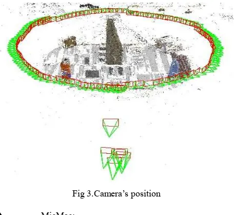
Figure 3 shows the 3D view of this experiment after the estimation of the camera poses, where the positions of the camera, footprints of images and tie-points in 3D are displayed.
Fig 3.Camera’s position
MicMac:
MICMAC creates the depth map by correlation between the reference image and other images that are used to find the information in the third dimension.
This calculation is made iteratively on sub-sampled images at increasingly high resolutions; i.e. the result obtained in the previous resolution is used for the next one.
2.2.3 Results:
The result of this calculation is a series of depth maps and 3D point clouds at different resolutions.
The formats of these data were not directly readable (the depth maps are 16 bits and the 3D point clouds are in hexadecimal format), so they were converted.
Figure.4.Depth map Figure.5.8Bits image
The 3D point clouds were obtained in .ply format and textured with the image reference (cf Fig 6). The depth map was converted to the tiff 8 bit format (cf Fig 5). It can be noted that these depth maps have the advantage of providing a simple and intuitive visualization of information on the third dimension and can replace a 3D point cloud (cf Fig 4).
Fig.6.Model 3D
2.3 Second experiment (3D model acquisition with tilt-shift lens)
2.3.1 Data acquisition:
For the second experiment, we used a wooden plank incised by hand at different depths (cf Fig 7). This experiment was made in a regular laboratory room, with no specific lighting. The objective was to represente complete, reliable, metric and precise 3D point clouds, using the tilt-shift lens for the different depths.
The advantages of using a tilt-shift lens are to have clear images for flat objects with a strong stereoscopic base.
The protocol that we have followed here involved acquiring a first set of images in an arc with a short 24mm focal. These images were then used for the orientation step (but, generally, not the matching step). They created depth of field in the scenes and freed all the internal parameters from their constraints. Next, it was possible to acquire images using the 90 mm focal tilt-shift lens. We turned the object around and took 24 images at regular intervals. Finally, we took 9 aerial images (seen overhead perpendicular from above the object) to create the digital elevation model.
Figure.7.The wooden plank
2.3.2 Tilt-shift lens:
The axis of the lens is normally perpendicular to the sensor. Changing the angle between axis and sensor by tilting a standard lens backwards or forwards is called lens tilt, or just tilt. By using the Scheimpflug principle (Bigler 2010), the focal plane can be changed. When the sensor and lens planes are parallel, as is the case in most cameras, the focal plane is also parallel to these two planes. If, however, the lens plane is tilted with respect to the sensor plane, the focal plane is also tilted according to geometrical and optical properties. The three planes intersect in a line below the camera for downward lens tilt. The tilted focal plane is useful, in that this plane can be made to coincide with a near and a far object. Thus, both near and far objects on the plane are in focus (Summerhayes 2008).
2.3.3 Data processing:
The data processing was carried out with Apero/MicMac tools.
The processing is carried out with Pastis in the same way as in the first experiment, except that here, in this case, we had to specify the parameter “All” to Tapioca: no restriction on the number of images and all the image pairs have to be matched because all the images are seen at the same time.
Estimation of the camera poses: Apero
We worked with the acquisition strategy described above using images taken with two different lenses of different focal lengths. To avoid divergences, we did an aerial triangulation to block images of the same focal length.
We ran APERO on this data set with the following strategy: In the first step, only the images acquired with the 24 mm lens were oriented; as they were appropriate to facilitate and stabilize orientation. In the second step, all the images were oriented. For the 24mm, we started from the previous solution; so the orientation of 90mm was facilitated because generally there was sufficiently multiple tie-points with 24mm to compute the initial value of orientation using space resection.
Figure 8 presents the camera positions that Apero gave us.
Figure.8. 3D model after computing camera poses
Calculation of depth maps and 3D models(MicMac):
The next step after the orientation of the images was the reconstruction of the scene using MICMAC in order to produce dense cloud points for this plank.
The calculation was carried out in ground terrain geometry because the scene here could be described by a single function Z = f(X; Y) (with X; Y; Z using Euclidean coordinates) with several parameters of MicMac to calculate the density correlation.
2.3.4 Results:
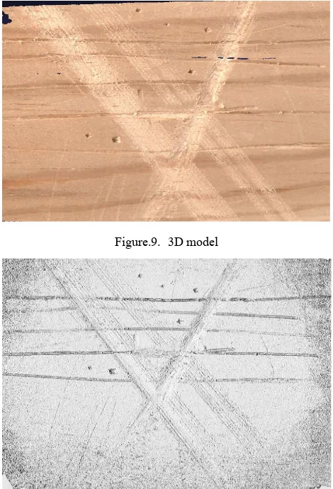
We can conclude from these results that a tilt-shift lens with our special protocol of taking images is effective for small object imaging in very close-range digital photogrammetry, because the 3D model could be reproduced with the details, even those incised by hand at different depths.
Figure.8. 3D model
Figure.9.Depth map with shading
Figure.9. 3D model
Figure.10.Depth map with shading
Figur.11. 8 bit image
3. QUALITY
to assess a 3D reconstruction is to analyze the shaded relief image, which emphasizes the possible artifacts.
We must work out quantitative assessments: exact size of the artifacts, difference between our model and a ground truth or a laser scanner acquisition...
4. CONCLUSION AND FUTURE PERSPECTIVES
We are aware that the thesis is continuous, and in front our results we have fascinating perspectives. First of all, regarding image acquisition, working out better lighting could be helpful, especially for reflective material such as shiny stones. Furthermore, the recording procedure should be at least made partially automatic. Finally, focus stacking procedures should be tested on real 3D objects (Macrophoto).
As far as data processing is concerned, parameter definition needs to be more thoroughly investigated, taking the specifications of the objects into account.
REFERENCES
Bigler, E., : Décentrement,bascule et règle de Scheimpflug en
petit et moyen formats,
http://www.galerie- photo.com/decentrement-bascules-scheimpflug-petit-moyen-format.html, 2010.
Chandelier, L., : La prise de vue photogrammétrique, December 2011 ; cours ENSG.
Cléry, I., : Pierrot-Deseilligny M., Cléry I. APERO, an Open Source Bundle Adjustment Software for Automatic Calibration and Orientation of a Set of Images. Proceedings of the ISPRS Commission V Symposium, Image Engineering and Vision Metrology, Trento, Italy, 2-4 March 2011.
CloudCompare, 2012. http://www.danielgm.net/cc/
Forstner, W., : Computer vision and remote sensing-lessons learned. In: Act of 52th photogrammetric week Computer Vision and Remote Sensing-Lessons Learned, Stuttgart, pp. 241–249, 2009.
Godet A., Pierrot Deseilligny M., de Luca L. : Une approche pour la documentation graphique 3D d'édifices patrimoniaux à partir de (simples) photographies », In Colloque Photogram-métrie au Service des Archéologues et des Architectes, SFPT-CIPA, Villeneuve lez Avignon, Septembre 2010.
Kasser, M. and Egels, Y., : Digital photogrammetry. Taylor & Francis, London, 2002.
Lowe, D.G., 2004, Distinctive Image Features from Scale- Invariant Keypoints International journal of computer vision, Volume 60, Number 2, pp 91-110.
MicMac 2012: MicMac, Apero, Pastis and the other beverage.
http://www.micmac.ign.fr/svn/micmac/trunk/Documentation/Do cMicMac/DocMicMac.pdf, 2012/10/21
Pierrot-Deseilligny, M.: MicMac, un logiciel pour la mise en correspondance automatique d'images dans le contexte
géographique, Bulletin d'Information Scientifique et Technique de l'IGN n° 77 (B1).
Pierrot-Deseilligny, M.: Cléry, I., Pierrot Deseilligny M. :Inter-face ergonomique de calculs de modèles 3D par Photogrammé-trie, In Colloque Photogrammétrie au Service des Archéologues et des Architectes, SFPT-CIPA, Villeneuve lez Avignon, Sep-tembre 2010.
Pierrot-Deseilligny M et al: Pierrot-Deseilligny, M., Cléry, I., Recent evolution in photogrammetry and 3d modelisation of natural spaces. Edythem proceedings, June 2011.
Pierrot-Deseilligny M. and Paparoditis N. 2006. A multiresolution and optimization-based image matching approach: An application to surface reconstruction from SPOT5-HRS stereoimagery. In IAPRS vol XXXVI-1/W41 in ISPRS Workshop On Topographic Mapping FromSpace (With Special Emphasis on Small Satellites), Ankara, Turquie, 02- 2006.
Scheimpflug, T., : Improved method and apparatus for the Systematic alteration or distortion of plane pictures and images by means of lenses and mirrors for photography and for other purposes, 1904.
Souchon, J.P., Thom C., Meynard C.,Martin, O. and Pierrot- Deseilligny, M. , IGN Cam V2 system: The Photogrammetric Record Volume 25, Issue 132, pages 402– 421, December 2010.