UAV BORNE LOW ALTITUDE PHOTOGRAMMETRY SYSTEM
Lin Zongjiana, *, Su Guozhonga, Xie Feifeia,b
aChinese Academy of Surveying and Mapping, Beijing, China. [email protected]
bSchool of Remote Sensing and Information Engineering, Wuhan University, Wuhan, China. [email protected]
COMMISSION I, ICWG I/V
KEY WORDS: Photogrammetry ; Surveying; System, Aerial; Platforms; Camera; Software
ABSTRACT:
In this paper,the aforementioned three major aspects related to the Unmanned Aerial Vehicles (UAV) system for low altitude aerial photogrammetry, i.e., flying platform, imaging sensor system and data processing software, are discussed. First of all, according to the technical requirements about the least cruising speed, the shortest taxiing distance, the level of the flight control and the performance of turbulence flying, the performance and suitability of the available UAV platforms (e.g., fixed wing UAVs, the unmanned helicopters and the unmanned airships) are compared and analyzed. Secondly, considering the restrictions on the load weight of a platform and the resolution pertaining to a sensor, together with the exposure equation and the theory of optical information, the principles of designing self-calibration and self-stabilizing combined wide-angle digital cameras (e.g., double-combined camera and four-double-combined camera) are placed more emphasis on. Finally, a software named MAP-AT, considering the specialty of UAV platforms and sensors, is developed and introduced. Apart from the common functions of aerial image processing, MAP-AT puts more effort on automatic extraction, automatic checking and artificial aided adding of the tie points for images with big tilt angles. Based on the recommended process for low altitude photogrammetry with UAVs in this paper, more than ten aerial photogrammetry missions have been accomplished, the accuracies of Aerial Triangulation, Digital orthophotos(DOM)and Digital Line Graphs(DLG) of which meet the standard requirement of 1:2000, 1:1000 and 1:500 mapping.
* Corresponding author.
1. INTRODUCTION
UAV (Unmanned Aerial Vehicles) refers to the unmanned aircraft, including the fixed wing unmanned aircraft, the rotor unmanned aircraft and unmanned airship, etc.
1.1 Why the Need for the UAV Systems (UAVS) for Low
Altitude Aerial Photogrammetry
In modern society, timely and fine surveying and mapping are needed, which need the help of UAVS for low altitude aerial photogrammetry.
1) The Need of Timely Surveying and Mapping
Nowadays satellite remote sensing and the general aviation remote sensing using the manned aircraft have been developed (National Remote Sensing Center, 2009), but there are many shortcomings in the timeliness for economic and social services . For example, in a place a satellite flew past at 10:30. At 11:00 in this place an emergency happened, so it is no hope to use this satellite in this day. Another example is that a road is planning to build with the length of 500km from east to west, so the images with 1m resolution for the engineering planning and design are urgently needed. If a satellite which gets images with the length of 11km every day is used, we must wait a month and a half even if every day is a sunny day. In modern society, this speed is so slow. Although the manned aircraft for aerial photogrammetry is a little flexible, with the restricted of cloudy day it is difficult to satisfy the timely need.
2) The Need of Fine Surveying and Mapping
In recent years, the high spatial resolution remote sensing is developing and popularizing most quickly in all developing directions of remote sensing technology, which means the high
spatial resolution remote sensing is fit for the need of the development of modern society. Now the resolution of satellite remote sensing images has reached to 0.3 meter, but more high-resolution is needed for the development of modern society, such as 5 centimeter (which matches to the map resolution of 1:500), and that the three-dimensional high resolution is also asked for. The requirement of elevation precision such as 15 centimeter is not only for the orthophoto, but also for the profile texture. The satellite remote sensing and big aerial remote sensing just pay attention to orthophoto, even the true orthophoto, which limit the development of three-dimensional high resolution. So only UAVS for low altitude aerial photogrammetry is the advantage technical mean for the current development of three-dimensional fine mapping.
1.2 The Advantage of UAVS for Low Altitude Aerial
Photogrammetry
1) The Advantage of Low Altitude Aerial Optics
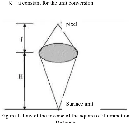
If a unit area of the ground just forms an image in the photosensitive pixel of the camera in the air (Figure 1), according to "the law of the inverse of the square of illumination distance” (Li Xiangning , 2009) in Photometry, the optical energy which this pixel can received is inversely proportional to the square of the distance of camera lens to the surface unit and proportional to the square of camera lens aperture.
2
2
' KD
d d
H
(1)
Where d= the luminous flux of the surface unit '
d =the luminous flux of the pixel received D = the camera lens aperture
H = the distance of camera lens to the surface unit, which can be understood as the flight height
K= a constant for the unit conversion.
Figure 1. Law of the inverse of the square of illumination Distance
2) How to Use the Advantage of Low Altitude
Although the low altitude aerial photogrammetry has the advantage of optics, it is difficult to use the advantage of low altitude. The greatest difficulty is security with low altitude. For example, if the height of the mountain on both sides of a valley is 1000 meters and the visibility in the valley is 500 meters, when we want to fly with the height of 500 meters, the UAV platform must be very light, small and can be fly with low speed, which restricts the load of the sensor also must be small and light. With the challenge of high resolution and high precision mapping, the sensor must be designed with special technology to meet the need of the light miniaturization and the photogrammetry software must be developed. So, how to address these issues comes down to the favorable utilization of the advantage of low altitude, would further guide to develop a special UAVS for low altitude aerial photogrammetry.
1.3 The Composition of the UAVS for Low Altitude Aerial
Photogrammetry
The UAVS for low altitude aerial photogrammetry consists of three parts, i.e., flying platform, imaging sensor system and data processing software.
2. THE PLATFORM OF THE UAVS FOR LOW
ALTITUDE AERIAL PHOTOGRAMMETRY
2.1 Available Platform of the UAVS for Low Altitude
Aerial Photogrammetry
The function of the flying platform is carrying the imaging sensor to the designated location of the air with the designated flying height and flying along a set route. At present, there are three kinds of available platforms of the UAVS for low altitude aerial photogrammetry, i.e., the unmanned helicopter, the unmanned airship and fixed wing UAV. In comparison, the unmanned helicopter is the most flexible which can take off and land in an very narrow field and fly along the arbitrary zigzag flight routes, even with the flight height below the maximum building, but the ability of anti-turbulence is the worst. If the engine failed, the unmanned helicopter would be down like
free-fall with no gliding buffer time. Because of most of its weight balanced by helium buoyancy, the unmanned airship has the good load performance and is safest. It can fly along the designed tortuous routes with low fight height and slow speed, so it suits for fine mapping. But the wind resistance ability of unmanned helicopter is lower, and the helium with relatively high cost carried more trouble. Fixed wing UAV has good high flight performance and work efficiency. On the contrary, the safety of low flight is poor and landing operation is difficult. So, these advantages and disadvantages of UAV platforms must be used in practice coordination and some corresponding remedial measures should be taken.
2.2 The Technical Requirements of UAV for Low Altitude
Aerial Photogrammetry
Not as most people imagine that UAV flies the higher the better, the sooner the better. The basic requirements of UAV for low altitude aerial photogrammetry is firstly to ensure flight safety and then to ensure the quality of images meeting the requirements of aerial survey. The two basic requirements lend to a series of technical requirements.
1) The Least Cruising Speed
The requirement of the least cruising speed is putted forward specifically for fixed wing UAV. There are two reasons. Firstly, only low flight speed can ensure the safety of the low altitude flight, especially on the undulating terrain, high building or between the narrow valleys. Secondly, with the load limitation, the imaging system loaded in the UAV generally has no the device for Image motion compensation, so when the high resolution images are required in the large scale mapping, the flight speed must be restricted (for example, the speed of the shutter is 1/1000s, and the flight speed is less than 36 km/h) to ensure the images clear (for example, the image motion is less than 1 center meter).
The reference (Wu Hanping, 2003) shows the formula of the least cruising speed for fixed wing UAV.
min
c
= the maximum lift coefficient of this kind UAV.According to Formula (2), in order to realize the flight in low altitude with low speed, the load of the UAV must be small, which puts forward the light miniaturization requirement for the imaging system.
For the unmanned helicopter and the unmanned airship, the requirement of the least cruising speed can be very easy to meet. 2) The Shortest Taxiing Distance
The requirement of the shortest taxiing distance is also putted forward specifically for fixed wing UAV. With the limitation of fuel load and the capacity of communication link, light-small UAV cannot fly with long endurance, so the Airport facilities pixel
Surface unit
all over the country which used for manned airplane cannot be effectively used by UAV. In order to bring its flexibility and mobility characteristics into full play, UAV must choose the simple runway to take off and land, so the shortest taxiing distance is the important application security index. The shortest taxiing distance is decided by the speed of take-off. The reference (Zhu Baoliu, 2008) shows the estimation formula of angle of the body of airplane, when the two main wheels is on the ground and the tail is about to touch the ground) corresponds.
According to Formula (3), for the same airplane, when its load w0 is bigger, the speed for take-off is greater. At present there are some kinds of light-small UAVs with the load of 5kg on the market, which generally have the speed of 60km/h for take-off. Now there are three kinds of methods to reach the speed for take-off, i.e., flat runway taxiing and take-off, vehicle take-off and ejection rack take-off. From the perspective of simple operation and wide terrain adaptation, it seems that ejection rack take-off has a relatively good development prospect. Compared with take-off, landing is simpler, which includes taxiing landing, hit the net landing and parachute landing. 3) The Level of the Flight Control
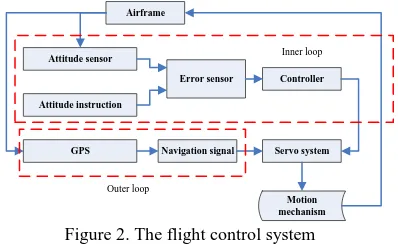
The flight control system plays as the pilot role in UAV, and sometimes is referred to as the autopilot. The principle diagram of the flight control system is shown in Figure 2 (Wu Hanping, 2003).
The minimum requirement of the flight control system is that airframe keeps flying smoothly along a given route under the condition of normal wind in the air.
The accuracies of positioning and altitude determination of the flight control system have a great effect on the quality of the images, which even affect the image overlap. This problem involves many aspects to be coordinated.
Airframe
Figure 2. The flight control system
The article takes the camera of Canon 5D with the lens of 24mm as example. If single camera is used with the angle of narrow edge view of 53°, the surface width covered by the
image is equal to the flight height. If double-combined camera is used with the angle of view of 90°, the surface width covered by the image is two times the flight height. If the offset (
) of the longitudinal and lateral overlap degree which is affected by the error of positioning and altitude determination of the flight platform is not more than 10% of the image width, so theTable 1. The limiting value of
of the longitudinal and lateral overlap degreeIf a UAV uses a simple and easy GPS to navigate, which has the positioning precision of 50m and the angle error of the altitude instrument of 10 degrees, the maximum of the
can be calculated in Formula (4) by considering the superposing of the greatest error. double-combined camera is used, it can meet the requirement of the mapping with the scale of 1:1000. If it wants to reach the requirement of the mapping with the scale of 1:500, the overlapping degree of the images should be increased or GPS and altitude instrument with more high accuracy should be used. 4) The Performance of Turbulence FlyingThe low altitude atmospheric air is often influenced by topography and the local temperature field of the surface feature, which forms the turbulence. With the mix of different wavelength of airs, this kind of turbulence has no regularity and forms the wind from head to foot, left to right and wind shear. This kind of turbulence makes the UAV that flies among them bumping left and right, which not only influences the quality of the photogrammetry, but also threatens the security of the aircraft.
The greatest damage from the low altitude turbulence to the fixed wing UAV is that the aircraft body is damaged with the bumping overloaded. In order to prevent the bumping overload, the measures can be taken, i.e., slowing down the speed, setting the centre of gravity of the equipment towards the back and using small aspect ratio wing or triangular wing (Zhu Baoliu, 2008).
Although the unmanned airship meeting turbulence also influents the quality of the photograph, it is mainly supported by the buoyancy to ensure the security. The unmanned airship, in contrast, performs best for resisting low altitude turbulence (Wang Sheng, 2008, Wang Sheng, 2008).
As mentioned above, the unmanned helicopter performs worst for resisting low altitude turbulence (Wu Hanping, 2003).
3. THE IMAGING SENSOR SYSTEM OF UAV FOR
LOW ALTITUDE
The imaging sensor system of UAV for low altitude should meet the condition of light load and the requirement of the high-resolution and high-accuracy aerial photogrammety for low altitude.
3.1 The exposure equation
The exposure equation in the photography system is shown as Formula (5) (Wang Zhijiang, 2009, Liu Songhao, 2006).
2
L = luminance of the object photographed (cd/m2)
S = the sensitivity of photosensitive element (the
standard of ASA)
K = the exposure constant (K=12.4).
The left of this formula is the internal exposure parameters and the right is the external exposure parameters. For a certain object and camera, the external exposure parameters are determinate, but the internal exposure parameters are adjustable. For example, if a camera has the sensitivity S800ASAand the luminance of the field of view L
250
cd m/
, with K12.4 and F
4
the time of exposure can be calculated, which ist
1/1000
s
. By considering the Formula (5) and Formula (1) together, we can obtain very intact physical concept. The higher of the light intensity of the ground object, the lower of the flight height and the bigger of the lens aperture of camera, the more abundant of the optical energy measured by the camera focal plane it will be. At the same time, if the sensitivity of the camera sensitization component is very high, the number of the lens diaphragm can be set up very big (That is the diaphragm very small) and the time of exposure can be set up very short to obtain the images with very high clarity and resolution. So, low flight height, great aperture and short time for exposure are three key technical indicators for UAV system.3.2 Optical Information Quantity
People think that the ratio of the information quantity of the camera with frame of 5K×4K to the frame of 4K×3K is 5:3, which is just the ratio of the data size of the images. The image information quantity is calculated according to the optical information theory (Tao Cunkan, 2004).
2
log (1
/
)
DOF s n
I
N
P
P
(6)Where
I
= the image information quantity (The unit is bit) simaging system which can be further expressed as Formula (7).
to the multispectral imaging andNto the polarize imaging are not discussed in the article.
s
N can be expressed as Formula (8).
where
=the optical wavelengthx
Now the ability of the information measurement of the imaging system is explanted from the sampling theory and information theory. As to a lens the aperture of which has been confirmed and a photosensitive array the noise level of dark current of which has been known, the extreme of the light power obtained by the lens is confirmed, so the extreme of the information quantity can be obtained. It is ineffectual in theory to increase the sample density beyond the sample theory. It is supposed that it is in the scope of the sampling theory. Because the noise power of each sensitization unit and the imaging area L Lx y are confirmed, the smaller of the imaging area cut, the less of the
signal power that each sensitization unit obtains will be, which will lead to the value of Ps/Pn and the average information
quantity of each image pixel reduced. So the total information quantity is not increased proportional to the number of image pixels. In practice, with the same lens the images obtained by the camera with the big number of plane array are not superior to the ones with the small number. But the accurate measurement will be done after the laboratory for optics measurement built up.
In practice, the freedom degree is regarded to the moving optical field. The imaging system is moving relative to the ground. The concept of the valid freedom is pointed out in literature(Tao Cunkan, 2004), which is explained too complex, so a understanding with clear physical concept is shown by figure in Figure 3.
Figure 3. The effect of image-motion to SNR
The left picture in Figure 3 shows the condition of the resting subject with no image-motion, in which, t1 to t2 is time of exposure, L is the width of the sensitization image pixel, and the rectangular of horizontal lines is represented as the optical power of the surface object received by the sensitization unit in the time of t1 to t2 (that is the power of Ps). The right picture in Figure 3 shows the condition of the moving subject with image-motion, in which the power of the sensitization image pixel receiving from the surface object in the time of t1 to t2 is not limited to L but increased the value of image-motion (
). The optical power is expressed by the parallelogram of the horizontal lines, the area of which is equal to the rectangle in the left picture, but by superimposing the left picture to the right, the ratio of areas of the no-overlap to the rectangle in the left picture is calculated as Formula (10).n
s
P
P L
(10)
By considering the Formula (6) and Formula (10) together, the image-motion reduces the SNR and information quantity of the image, the intensity of which is depended to the ratio of
to the image pixel size. Obviously, the influence to the photogrammetry with low resolution is not big, but it is worth paying attention to this influence with high resolution. The method of reducing
is shorten time for exposure or reducing the flight speed.3.3 Combined Wide-angle Digital Cameras
1) Why the Need for Combined Wide-angle Digital Cameras Light-small UAV must load light to guaranteeing safe. Now the effective load of the fixed wing UAV is generally less than 5Kg,
so, this kind UAV cannot load the top-grade camera for photogrammetry with the weight up to one hundred kilograms that is used in the manned airplane. At present, the less top-grade ordinary digital camera is adopt with the frame of image more than 3K×4K. The reasons for developing double-combined camera basing on the single camera are shown: a) To expand the capacity of the array sensor
The capacity of the array sensor is the key technology characteristic of the digital camera. The big array sensor is expensive and not easy to buy, so, the method that many cameras are fitted together as a big array camera is the advanced technological achievement of the world in recent years (National Remote Sensing Center, 2009).
b) To form the view field with wide angle
The angle of view is the important technical indicator in the aerial camera. There are two functions about wide angle of view, i.e., the wide angle of view from the longitudinal direction improving the base-height ratio to improve the quantity of height measurement and the wide angle of view from the lateral direction improving the surface width covered by the images to raise the efficiency of the flight and reduce the quantity of the control points laid in the outdoors. The double-combined camera which is mentioned in below only expands the angle of view from the lateral direction and has the second function. Of course, if necessary, the double-combined camera can be repacked with expanding the angle of view from the longitudinal direction.
2) The double-combined wide angle camera with function of self-calibration
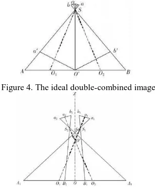
The ideal structure of double-combined wide angle camera is shown as Fig.4, that is the lens centers of two cameras are totally coincident and the view fields of two cameras are just spliced with no gap or overlap. However, the real camera has the size and the ideal state can’t be realized. So, the geometric structure is designed as Fig.5, in which two cameras slope with the same rolling angle (
) in opposite directions, which forms the expanded view of angle (ASA ) and the overlap (1 2 B SB )(1 2 S is the center of the fictitious equivalent projection.). The images in the overlap (B B1 2) can be used to do the self-calibration, sothe initially arranged error of the elements of relative exterior orientation of two cameras is confirmed.
Figure 4. The ideal double-combined image
Figure 5 The practical double-combined image
In fact, the practical mechanical structure of the double-combined camera is designed as Fig.6, in which two cameras successively take pictures along the course. The first camera slopes left with the angle
and the second one slopes right with the angle
. The delay exposing times of two cameras are respectively accurately measured by the oscillograph. Considering the time difference of exposing delay of two cameras in the synchronized exposure device and the compensated time difference which is inversely calculated by the space between two cameras along the course with the cruising speed, the delay time difference of the synchronized exposure device of two cameras is designed. By using the designed synchronized exposure device, two cameras can reach the “synchronous exposing” on the whole and the influence of its residual time difference will be dispelled by the method of self-calibration.According to the routine photogrammetric method for camera calibration, each camera in double-combined camera takes the photo from the calibration filed indoor (or outdoor) to calculate the elements of interior orientation, radial distortion difference and tangential distortion difference with the formula of inner orientation and distortion difference.
,p2= the coefficient of tangential distortion difference.
The double-combined camera must be calibrated by taking the photo from the calibration filed and its elements of relative orientation are calculated with the formula resection and transformed into the coordinate system which regards the symmetrical centre line of two cameras as the projection axle of the fictitious equivalent centre. The result is that two images are converted into an equivalent image with the projection from the fictitious centre, which is shown in Fig. 7.
Figure 6. The mechanical structure of double-combined camera
Figure 7. The equivalent image by projected
If the elements of the relative positing orientation between two cameras are calculated with no error and the expositing of two cameras is strictly synchronous, the overlap of two images will be totally coincident to each other as shown in Fig.7. However, the overlap of two images will not be totally coincident to each other with the two errors.
The view differences (xand y) of all feature points in the overlap of the images will be detected by image matching, which is used to calculate the elements of the relative orientation with the equation of least squares method.
2 the projection axle of the fictitious equivalent centre
H=the distance from the fictitious projection surface to the projection centre. relative position element of the double-combined camera to their approximate value
, , , , ,
images can be spliced into one image equivalent as the one from one camera.
Wang Hui (2003) has further investigated in the problem about the lens centers of two cameras in the double-combined camera not in the same position. Her achievements show that the residual error of the double-combined image will not be corrected with a certain distance between two cameras on the bumpy terrain. So, with the ground undulation not exceed 1/3 of the flying height, the distance between two cameras should be accurately limited smaller than 0.3 pixels to reduce the splice error.
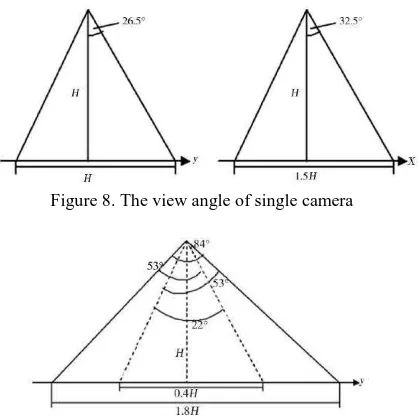
The designed fixed wing UAV loading double-combined camera is taken for instance. Each camera used for double-combined camera is Canon 5DMarkII camera with the focal length of 24mm, the size of the frame of 3.7K×5.6K and the view angle of 53°×65°, whose long side is located in longitudinal direction (the x direction) and short side in lateral direction ( the y direction). The view angle range of single camera is shown as Fig.8.
The profile of the view angle of double-combined camera in the lateral direction is shown in Fig.9. It shows that the overlap angle of two cameras is 22°which is equivalent to 40% of the view angle of single camera, is regarded as the overlap for self-calibration. The wide view angle of double-combined camera is up to 84°that is 1.8 times of the flight height(H).
Figure 8. The view angle of single camera
Figure 9. The lateral view angle of double-combined camera If the width of the lateral overlap is designed as 0.3H, the width of double-combined camera shipping line is 1.5H, which is basically two times the single camera with shipping line of 0.7 H.
3) The self-calibration and self-stabilizing four-combined camera
If the work principle about double-combined camera is expanded to longitudinal and lateral directions, the width of strip can be expanded and the base-height ratio with the overlap in the longitudinal direction can be increased to improve the measure quality of altitude. Basing on double-combined camera, four-combined camera improves two technological measures.
a) The special overlap relationship in four-combined camera shown in Fig.10 and Fig.11 strengthens the self-calibration function to guarantee four-combined camera system light and small with high accuracy.
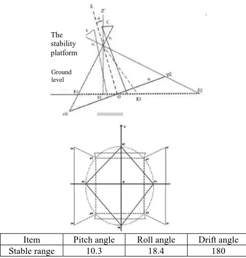
b) The mechanical damping, measurement of altitude with electronic equipment and the software in Fig.12 and Fig.13 are used for four-combined camera, which realizes the dip angle of images from lager to little. So the stabilizing device for platform is given up to further light the weight of the imaging system.
Figure 10. The design of the self-calibration function of four-combined camera
Camera X Y Z
k
1 0.0000 0.0000 0.0000 -23.9667762 0.3459957 0.0000000 2 0.1107 -.0744 -0.0297 0.1989228 37.8507554 -0.3283583 3 0.0031 -0.1576 0.0012 23.8693632 -0.3135667 -0.3038560 4 -0.1177 -0.0949 0.0013 -0.104663 -38.0568293 -0.1278548
Figure 11. The four-combined equipment image
Damping type stable platform Control the camera's pitching and rolling in 8 degrees
Attitude measuring instrument Real time measurement of the camera pose
Data processing software
Splice virtual image according to the positions of
the camera
Figure 12. The structure of the stability platform
Item Pitch angle Roll angle Drift angle
Stable range 10.3 18.4 180
Figure 13. The images cutting of the stability platform
4. THE DATA PROCESSING SOFTWARE FOR UAVS
4.1 Production technical process of the UAVS for low
altitude aerial photogrammetry
Flight preparation of UAV Route planning Camera calibration
Low altitude aerial photogrammtery using UAV
Mosaic and sort images Free net aerial triangulation photogrammetry
Bundle block adjustment Data of GPS and attitude
sensor
Error equation of control points
Control point measurement in outdoor
DOM production with differential rectification
DEM production with images matching
DLG production with aerial survey instrument
Figure 14. The flow chart about the UAVS for low altitude aerial photogrammetry
4.2 The software named MAP-AT
The aerial photogrammetry software for the data obtained by the ordinary manned airplane has already been very mature (Yuan Xiuxiao, 2001), which cannot solve the problems meted by the low altitude aerial photogrammetry with UAV. So, it is necessary to develop the new software with independent copyright for the low altitude aerial photogrammetry with UAV. The software named MAP-AT inherits the advantages of the existing advanced photogrammetry software at home and abroad, i.e.,
1) Automatically arranging the images with POS data,
2) Automatically choosing the relative orientation points and connecting points to finish the construction of the free aerial triangulation network,
3) Points matching with multi view images, which is used to realize the accurate positioning through bundle adjustment, 4) Using the mapping instrument which is accustomed in production, such as Vituozo and JX-4, etc.
On that basis, the following new functions is developed, i.e., 1) The functions of automatically checking connecting points and manual work for matching points, which are used for the failure of points automatically matching in the big deformed images with large dip angle ,
2) The function of manual intervention works with many kinds of different situations in the TIN inserting,
3) The functions of images mosaic, cutting and error checking for the combined wide angle camera,
4) The big scale mapping symbols are upgraded to the 2008 national standard version, which supports the function of editing maps for the DLG production.
5) The function for supporting the structure of three dimensional model of the building (Gui Dezhu, 2010).
5. EXPERIMENTS AND CONCLUSION
5.1 Experiments
On the basis of above-mentioned principles, we have designed the fixed wing UAVS loading the double-combined camera with the lateral wide angle, the unmanned airship loading four-combined camera and self-stabilizing imaging system and the low altitude aerial photogrammtry software named MAP-AT. Dozens of product experiments in Guangzhou, Wuhan, Qingdao, Weihai, Shenzhen, Tianjin, Chongqing, etc. proves that the fixed wing UAVS loading the double-combined camera can fulfilled the production requirement of DOM and DLG in the scales of 1:2000 and 1:1000, the unmanned airship loading four-combined camera can fulfilled the production requirement of DOM and DLG in the scales of 1:2000 , 1:1000 and 1:500, and MAP-AT cooperating with Vituozo or JX-4 can finish the task of DLG production (Peng Xiaodong, 2010, Sun Jie, 2003).
5.2 Conclusion
It is demonstrated that the UAVS for low altitude aerial photogrammetry can be used in aerial photogrammetry productions, and is promising in exploiting new markets of timely and fine surveying and mapping, which entitles it to be an effective complement to satellite remote sensing and manned vehicle aerial photogrammetry.
REFERENCES
Cui Hongxia, 2006. Research on Photogrammetry with Digital Frame Camera based on Low Altitude Unmanned Aerial Vehicle (UAV) System. Ph.D. Thesis, Wuhan University. Ground
level The stability platform
Gui Dezhu, 2010. Study on Construction of 3D Building based on Wide-angle and Combine Camera Images From UAV. Ph.D. Thesis, China University of Mining and Technology.
Jones MCA, 1997. Unmanned Aerial Vehicles (UAVs)–an Assessment of Historical Operations and Feature Possibilites [R], AU/ACSC/0230D /97-03.
Li Xiangning , 2009. Engineering Optics. Beijing, Science Press.
Lin Zongjian, 2008. UAV for Mapping. ISPRS, 2008 Conference, ISPRS Beijing.
Liu Songhao, 2006. Photonics Technology and Application. Beijing, Science Press.
Liu Zhaoqin, 2008. Study on Wide-angle and Light Small Combined Digital Camera System for UAV. Ph.D. Thesis, Wuhan University. Ph.D. Thesis, Shandong University of Science and Technology.
National Remote Sensing Center, 2009. Advance in Geo-spatial
Information Science and Technology. Beijing, Publishing
House of Electronics Industry.
Peng Xiaodong, 2010. Research of Low Altitude
Photogrammetry of Unmanned Airship. Ph.D. Thesis, Wuhan University.
Sun Jie, 2003. The Aapplication of Remont Sensing
Technology in Land Management of CHINA. Remote Sensing Information, pp. 49-51.
Tao Cunkan, 2004. The Optical InformationTheory. Beijing, Science Press.
Tsach S, etal, 2007. Develepment Trends for Next Generation UAV Systems. AIAA infotech Aerospace 2007 Conference. AIAA 2007.
Wu Hanping, 2003. Introduction to UAV Systems. Beijing, Publishing House of Electronics Industry.
Wang Hui, 2003. Modeling and Analyzing of Geometric Joint Error for CCD Matrix Images of Digital Aerial Camera. Acta
Geodaetica et Cartographica Sinica, 20(4), pp. 257-262.
Wang Sheng, 2008. Airship Technology. Beijing, Science Press. Wang Zhijiang, 2009. Practical Optical Technology Handbook.
Beijing, National Defence Industry Press.
Wu Fei, 2008. Introduction to Modern Airship Design. Beijing, Science Press.
Yuan Xiuxiao, 2001. GPS Assisted Aerial Triangulation Principle and Application. Beijing, Surveying and Mapping Press.
Yan Chen, 2008. Measures of information in remote sensing imagery and area-class maps . 2008 Conference. ISPRS Beijing, 2008.
Zhu Baoliu, 2008. UAV Aerondynamos. Beijing, Aviation Industry Press.