PANORAMIC EPIPOLAR IMAGE GENERATION FOR MOBILE MAPPING SYSTEM
T. Chen*, K. Yamamoto, S. Chhatkuli, and H. Shimamura
PASCO CORP. R&D CENTER, 2-8-11 Higashiyama Meguro-Ku, Tokyo 153-0043, JAPAN
–
chentian@iis.u-tokyo.ac.jp
Commission V, ICWG V/I
KEY WORDS: Photogrammetry, Omni-directional camera, Panoramic epipolar image generation, Stereoscopic viewing, Image matching
ABSTRACT:
The notable improvements on performance and low cost of digital cameras and GPS/IMU devices have caused MMSs (Mobile Mapping Systems) to be gradually becoming one of the most important devices for mapping highway and railway networks, generating and updating road navigation data and constructing urban 3D models over the last 20 years. Moreover, the demands for large scale visual street-level image database construction by the internet giants such as Google and Microsoft have made the further rapid development of this technology. As one of the most important sensors, the omni-directional cameras are being commonly utilized on many MMSs to collect panoramic images for 3D close range photogrammetry and fusion with 3D laser point clouds since these cameras could record much visual information of the real environment in one image at field view angle of 360° in longitude direction and 180° in latitude direction. This paper addresses the problem of panoramic epipolar image generation for 3D modelling and mapping by stereoscopic viewing. These panoramic images are captured with Point Grey’s Ladybug3 mounted on the top of Mitsubishi MMS-X 220 at 2m intervals along the streets in urban environment. Onboard GPS/IMU, speedometer and post sequence image analysis technology such as bundle adjustment provided high accuracy position and attitude data for these panoramic images and laser data, this makes it possible to construct the epipolar geometric relationship between any two adjacent panoramic images and then the panoramic epipolar images could be generated. Three kinds of projection planes: sphere, cylinder and flat plane are selected as the epipolar images’ planes. In final we select the flat plane and use its effective parts (middle parts of base line’s two sides) for epipolar image generation. The corresponding geometric relations and results will be presented in this paper.
* Corresponding author.
1. INTRODUCTION
MMS(Mobile Mapping System) is an important geographic data collection technology developed in the last decades due to the advance and progress in mobile positioning technology, modern communication technique, spatial information technology and imaging sensors etc., and has been mainly used to map transportation infrastructure features accurately and economically. The demands for large scale visual street-level image database construction by the internet giants such as Google and Microsoft have made the further rapid development of this technology.
A mobile mapping system can be defined as "a moving platform, upon which multiple sensor/measurement systems have been integrated to provide three-dimensional near-continuous positioning of both the platform and simultaneously collected geo-spatial data, with no or limited ground control using single or multiple GPS base stations" (Grejner-Brzezinska, 2002). It involves the integration and management of different data collection devices along with data processing and management software to provide the user with the location of spatial features that exist on the earth. Three basic measurement components comprise most MMS: global positioning system (GPS), inertial measurement unit (IMU) or other form of dead-reckoning sensor, and an image capture system. Thus, a mobile mapping system that utilizes multiple sensors is “the product of integrating the concepts of kinematic geodesy and digital photogrammetry, to acquire, store, and process, measurable quantities that
sufficiently describe spatial and/or physical characteristics of a part of the Earth’ssurface” (Mostafa and Schwarz, 2001). The LiDAR technology offers one of the most accurate, fast, expedient and cost-effective ways to capture ground surface information and has been operational in airborne mapping systems for surface and object reconstruction since the mid-1990s. Now, all most of reported MMSs adopt this kind of technology to capture small (relative to those captured from an aircraft) irregular objects such as buildings, earthworks and landforms such as cliff faces which can be profiled and monitored during mining. However, they need high quality GPS/ IMU devices to obtain high accurate position and attitude information for 3D laser point clouds geo-referencing. This makes the whole system very expensive and will limit the applications of MMSs for most users. Despite this,the GPS/IMU devices do not often work well in urban areas, because the GPS satellite signals are frequently blocked by the high buildings, trees, the elevated electric cables, etc., these factors and the IMU time drift errors will seriously lower the geo-referencing accuracy for 3D laser point clouds. Moreover, these laser points are still sparse and frequently occluded by moving cars, buses and pedestrian, and could not be still compared with the vast amount of geo-registered panoramic imagery. On the other hand, there is no commercial software capable to handle the data from different mobile mapping systems so far. Automation of the procedures of mobile mapping data processing has not been extensively researched since most efforts seem to have been made in the development of the data acquisition systems (Li,
1999). Compared with the traditional mapping methods such as aero photogrammetry with digital images, GPS and total station on site measurements, the current application areas of MMSs are still narrow and small.
As the basic sensors of the original MMS prototype, digital cameras are still taking the major role to collect ground images for stereo measurements, fusion with laser point, texture for 3D modelling and ortho-image generation. In this paper we will emphasize the functions of images captured with Point Grey’s Ladybug3 mounted on the top of Mitsubishi MMS-X 220 for stereoscope measurements with the exception of their other applications such as fusion with laser point cloud, texture extraction and image-based navigation.
2. COMPONENTS AND DATA PROCESSION OF MITSUBISHI MOBILE MAPPING SYSTEM
Since the early 1990s, the concept of MMS has evolved from rather simple land-based systems to more sophisticated, real-time multi-tasking and multi-sensor systems, operational in land, water and airborne environments. Mobile mapping technology has made a remarkable progress, notably expanding its use in remote sensing, surveying and mapping markets. New systems are being developed and built for specialized applications, in support of land-based, water-based and airborne imaging sensors, aimed at automatic data acquisition for GIS database. This chapter mainly describes the components, data acquisition and post procession of the Mitsubishi MMS-X220.
2.1 Components of the Mitsubishi MMS-X220
Essentially, an MMS has two main components: the mapping sensors and the navigation system. Mapping sensors are typically digital cameras, but may include additional sensors such as laser scanners, multi-spectral scanners, or radar. Based on the measurements from the mapping sensors, the location of features of interest relative to the platform on which they are mounted can be estimated either by direct range measurements when laser scanners are employed, or indirectly, by space intersection, where 3D coordinates of the points are established by the intersection of two ray paths using at least two cameras. If the carrying platform is, in turn, directly georeferenced by the navigation component, then the absolute position of the mapped features can be determined.
The navigation component of an MMS, typically a GPS receiver combined with an inertial navigation system (INS), should be capable of continuously determining the position and attitude of the system. Typically, GPS serves as the main positioning sensor by measuring ranges and range rates from a GPS receiver's antenna to the GPS satellites. Antenna-to-satellite intervisibility is a must. The accuracy degradation of the GPS solution is due to poor satellite spatial distribution, loss of lock, and satellite signal blockage. In addition, even by introducing multi-antenna configurations, the frequency of attitude determination may be too low (say, only 10 Hz), which limits their use for some systems such as LIDAR (light detection and ranging) and other applications with expected high dynamics.
On the other hand, an INS acts as the main attitude sensor. The INS typically consists of three orthogonal accelerometers and three orthogonal gyroscopes. The accelerometer and gyroscope triads are parallel and establish the INS coordinate system. The three accelerometers sense the body-frame linear accelerations
while the gyroscopes sense the body-frame angular velocities with minimum time delay. The estimation of the relative position and attitude is accomplished by integrating the sensed signals after being transformed to the appropriate computational coordinate frame.
For short time intervals, the integration of acceleration and angular rate results in extremely accurate velocity, position, and attitude with almost no noise or time lags. However, because the navigation information is obtained by integration, they exhibit low frequency drift. To obtain accurate navigation information over all frequencies, the INS navigation solution should be updated periodically using external measurements. For this purpose, GPS velocities and positions are used as update measurements, which complement the INS output in an ideal way. Also, other navigational aids, such as odometers, inclinometers, or barometers, may provide additional observations for some subset of the navigational state. The successful use of an MMS critically depends on both the accuracy and the continuity of the navigation solution. A perfect MMS is, therefore, one that can operate without interruption in areas where a discontinuity in the data from one or more of the navigational sensors is expected.
Figure 1. This van is equipped with a Mitsubishi MMS mobile mapping system, showing its cameras, laser scanners and three GPS antennas mounted together on its roof platform. (Source:
Mitsubishi Electric)
Mitsubishi MMS-X220 Mobile Mapping System (Figure 1) is a dynamic and cost-effective measuring system for acquiring high quality 3D geospatial data. Special attention has been paid to the development of post-processing software; a full concept is available to our end users. The applications of this system include inventory and management of traffic arteries, like streets, highways and airports, along with detailed infrastructure, large scale digital mapping, follow-up and documenting of construction sites (“as-build”) and city planning, only to mention a few. This product has been developed jointly by staff members of Waseda University in Tokyo in collaboration with Mitsubishi since 2006. Several examples are already in use in Japan. The system is being offered in four different versions. (i) The most basic version is the MMSA, which has three roof-mounted GNSS receivers arranged in a triangular pattern; an IMU; an odometer; and a sensor control box. This version is being offered mainly as a vehicle positioning device, with the choice of cameras and laser scanners and their integration being left to the customer. (ii) The second version is the MMS-S which is offered with two video cameras and two laser scanners in addition to the positioning devices included in the basic MMS-A version. (iii) The third version MMS-X is offered with multiple (up to 6) cameras and (up to 4) laser scanners, again in addition to the
positioning instrumentation included in the MMS-A version. (iv) The new version MMS-X 220 is offered with two video cameras, two laser scanners and one Ladybug multi-camera unit from Point Grey Research that carries out the 360 degree panoramic imaging with framing rates of up to 15 frames per second in addition to the positioning devices included in the basic MMS-A version. In the literature that accompanied this introduction, the supplier of the dual-frequency GNSS receivers was stated to be Trimble; the IMU was from Crossbow, using a FOG gyro supplied by Japan Aviation Electronics; the frame cameras were supplied by IMPERX from the United States; while the laser scanners were the ubiquitous LMS 291 model from The SICK. In the version MMS-X 220, all of these imaging and scanning devices send their data to a central control box which then passes it via a high-speed FireWire-B (IEEE1394-B) link to the PC that is mounted in the vehicle for the recording and processing of the data. An LCD display screen allows the vehicle’s crew to monitor the connectivity and operation of all the various positioning, laser scanning and frame imaging devices.
2.2 Data Acquisition of the Mitsubishi MMS-X220
The data acquisition is done continuously from all sensors through a central control box to steer and control the data flow. It is achieved by the Data Acquisition Module (DAM) software. The DAM software synchronizes and records the data from IMU, GPS, cameras and laser scanner to hard disk. The system is calibrated internally, relatively and externally. The collected multi-camera images, panoramic image sequences and laser range data allow for surveying of any point visible in the images or in laser data. The measured coordinates are presented in a global coordinate system. The Ladybug camera is mainly used to collect 360° panoramic images of ground for improvements of GPS/IMU data by serial image analysis and acquisition of the features and objects along the roads, while the mono side cameras collect image sequences with overlap of 90 % for surveying of building facades or side walks. The working interval of image acquisition is from 2m to 4m from all cameras at moving distance. The scanners in MMS-X 220 scan from 38000 points per second a with 360° opening angle. The range of the scanners is up to 65m. The combined image and laser data allows for documentation and 3D surveying of surroundings of the van. 2.3 Data Post Procession of the Mitsubishi MMS-X220
Once acquired in the field, the data needs to undergo post-processing, which can be divided into several steps for MMS-X 220. The first step is calculation of the MMS trajectory using standard GPS data processing software such as GrafNav since the trajectory is used as a basis for all sensor orientation and position calculations to follow. The other steps involve processing of images from digital cameras and data from laser scanners.
The trajectory calculation method is based on integration of data from a GNSS receiver, IMU, and external odometers, allowing to achieve required accuracy even in areas where the GNSS positioning alone is unreliable or entirely impossible. This happens mostly in urban areas where signal from satellites is often blocked by high buildings, trees and other objects. The absolute system position calculated using the GNSS technology serves for compensating errors in measurements obtained from the inertial measurement unit. On the other hand, the relatively stable position (in a short-term scope) determined by IMU can be
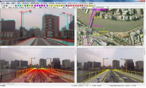
used to overcome areas where GPS fails. Additional information is received from odometers measuring speed and distance travelled depending on the rotation of wheels of the vehicle. There are two trajectory calculation methods that became widely used in practice, referred to mostly as loosely and tightly coupled. Both methods utilize Kalman’s filters while when the loosely coupled method is applied, the path is pre-calculated using the GNSS differential method first. This path is then used when processing IMU data to update position and speed. When the tightly coupled method is used, the GNSS/INS data is processed simultaneously, making it possible to use at least two satellites for a phase update, which means a great advantage in difficult conditions with limited satellite signal reception. Image data processing depends on the type of digital cameras in use. Some cameras store images directly in classic formats, such as JPEG, TIFF or BMP while others use various raw formats instead to increase the data transfer rates and capture up to tens of hi-res images per second. This makes the demands for data post-processing even higher. In MMS-X 220, two 5M pixels video cameras and one Ladybug 3 spherical camera which can create panoramic images with the high resolution of 5400x2700 pixels during post-processing. For these image calculations of exterior orientation parameters are added based on the trajectory calculated. The resulting data can be used for fusion with laser point clouds and stereoscope 3D measurement based on the ground photogrammetric principle through the MAPAT-S 4.2 software which can process aero and MMS hybrid image and laser data simultaneously (See Figure 2).
Figure 2. MAPAT-S 4.2 software and aero/MMS hybrid image
and laser data process simultaneously (Left up view for aero/ MMS images stereo measurement; Left down view for left aero/MMS image mono measurement; Right down view for right
aero/MMS image mono measurement; and Right up view for MMS’s trajectory display or aero image bird view.) The laser georeferencing step includes laser point clouds processing measured data, representing information on transit times of emitted rays and the incoming light intensity is converted to a cloud of laser points. Colors can be assigned to the points using the images captured, creating a realistic 3D model of the area of interest. Every laser point – and there are several tens of millions of these created within data collection – carries information on the position, reflection intensity and color, which is usually stored as RGB. Through the MAPAT-S 4.2 software, the information from laser point clouds could be evaluated by overlapping the laser point clouds with MMS video images or Ladybug panoramic images as Figure 2. The 3D information of ground objects such as roads, buildings, and auxiliary objects could be extracted from the georeferenced laser point clouds.
For most all MMSs, the above data post procession steps are the most fundamental operating contents. In addition, refining the MMS trajectory and attitude data for high accuracy in case of GPS gaps in the environment of urban areas with serial image analysis such as bundle adjustment and image based stereo measurements are also necessary steps. In the next section, we will describe the epipolar image generation of Ladybug 3 mounted on MMS-X 220 for 3D stereo measurement.
3. EPIPOLAR GEOMETRY OF STEREO PANORAMIC IMAGES AND PANORAMIC EPIPOLAR IMAGE
GENERATION
Panoramic images are a new type of visual data that provide many new possibilities as compared to the classic planar images since panoramic images allow observing a scene from various viewing directions. Large scale GIS for street-level viewing, geographical mapping and other location-based visualizations, high end security and surveillance, city planning, simulation and measurement analysis, entertainment solutions for lighting models, full dome projection content, tele-presence, virtual navigation and other immersive experiences are examples of such interesting applications. Other more applications of panoramic images for 3D close range photogrammetry have been also reported due to their abilities to record much visual information of the real environment in one image at field view angle of 360° in longitude direction and 180° in latitude direction, especially their usage in the narrow spatial sites. The most famous application example is that Google Streetview has used panoramic cameras over the world to collect geo-referenced panoramic images of city environments to expand the Google web GIS database for more detail view of the ground surface. The use of panoramic photographs dates back until the early years of photography. First panoramic images have been recorded with rotating frame cameras or by swing lens techniques. During the 19th century, panoramic cameras have been combined with angular reading in order to measure the rotation angle of the camera. Consequently, panoramic photography and the use of photo-theodolites were closely connected. These methods only create analog panoramic photographs. The current digital panoramic images are mostly created by off-the-shelf stitching programs that can match uncalibrated frame images into a cylindric projection with limited user interactions or using spherical surface reflection mirror just for observing a scene of natural environments, e.g. for touristic purposes and low accuracy metric site documentation for facility management applications (Chapman & Kotowski, 2000), or for the combination with 3D laser-scanners. Some researchers (Amiri Parian & Gruen, 2005; and Schneider & Maas, 2005) have developed camera calibration approaches that, in addition to photogrammetric interior orientation parameters, model the specific rotating line-scanning characteristics such as tumbling of the vertical rotation axis. A more detailed view on the history of panorama photogrammetry can be extracted from Luhmann (2005).
With the emergence of high resolution panoramic cameras such as Point Grey’s Ladybug3 and Ladybug5, much more attentions of these will be put on their photogrammetric processes such as image matching, DEM and ortho-photo generation, aerial triangulation, map compilation, and stereoscopic viewing. This will cause another research and application great mass fervor in photogrammetry field.
In this section we will detail the epipolar geometry of panoramic image and the algorithm for panoramic epipolar stereo image pair generation.
3.1 Panoramic Camera and Its Geometry
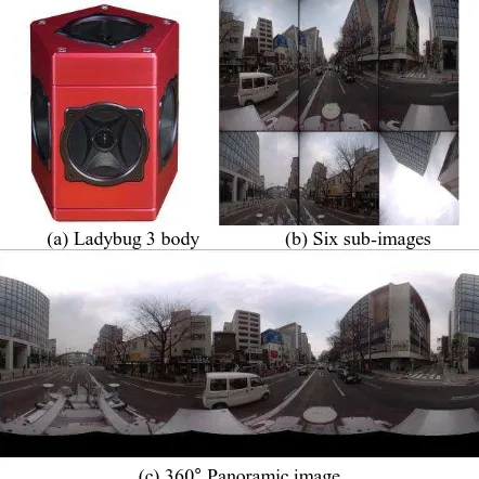
Arising from the speed of movement of the mapping vehicles and the close proximity of the target objects (of a few tens of meters), the multiple high framing rate digital frame cameras and 360 degree panoramic cameras are commonly used to collect full cover images of the street scene. The Mitsubishi MMS-X 220 is equipped with two 0.5M pixels video cameras and one Point Grey Research, Inc.’s Ladybug 3 spherical camera (Figure 3). The Point Grey Research, Inc.’s Ladybug series of multiple cameras have been adopted widely for use in mobile mapping systems. The company’s Ladybug2 multiple camera unit has six Sony CCD digital video cameras. Five of these cameras are arranged concentrically in a horizontal ring pointing outwards to produce a 360 degree panoramic image within the horizontal plane, with the sixth camera pointing vertically upwards. These cameras have a FireWire-B (IEEE1394-B) 800 Megabit interface and cabling to provide camera control and power and to implement video data transmission at the rate of 15 uncompressed frame images per second, each image being 1,024 x 768 pixels (= 0.8 Megapixels) in size. The Ladybug3 unit also has a set of six Sony CCD cameras arranged in a similar circular five-camera configuration (plus a single vertical camera) but with still larger formats (1,600 x 1,200 pixels). Thus it can generate six 2M images that can be streamed as uncompressed images at the rate of 7 frames per second or as compressed JPEG images at a 15 frames per second rate. Each Ladybug multiple camera unit can be supplied attached to a mast that can be mounted on a roof rack that has been placed on top of the mapping vehicle to provide a clear view of the surrounding objects.
(a) Ladybug 3 body (b) Six sub-images
(c) 360° Panoramic image
Figure 3. Ladybug3 and its six sub-images and the merged 360° panoramic image.
Since the camera’s sensors have been accurately calibrated, it is possible to fuse the six images to form an almost complete spherical panorama. This panorama can therefore be considered to have been produced by a central projection camera that collects all light rays coming from all directions, incident on a point in space. The resulting two-dimensional plenoptic function can then be re-projected on any type of surface. We use the
normal spherical surface as the projection of panoramic image (Figure 3).
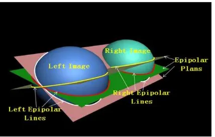
As frame camera, if the knowledge about the panoramic camera and relative viewpoints is available, the epipolar geometry could be constructed. Figure 4 shows the epipolar geometry for a panoramic camera.
Figure 4. Epipolar geometry for Ladybug 3.
From figure 4 it is easy to see that any 3D point of a scene and the two projection centers of the left and right panoramic images form one spatial plane which is called the epipolar plane of the 3D point. On the camera projection surfaces, the epipolar plane forms two curves known as the left epipolar line and the right epipolar line. The epipolar line is a sinusoid (Figure 5), which also illustrates the change trend of stereo consequent and the accuracy for 3D measurement. All epipolar lines intersect two points whose connection is the base line of the two stereo images. At the two intersections, both the stereo consequent and the accuracy for 3D measurement are the worse.
Figure 5. Sinusoid epipolar lines on panoramic image. 3.2 Panoramic Epipolar Image Generation
Although the epipolar curves on the panoramic camera projection surfaces could be found, they are not conveniently used for the determination of homologous points from original panoramic images and the measurement through stereo viewing. We should transfer these images into the true epipolar images on which all epipolar lines are horizontal parallel straight lines as those of the frame images (Figure 6).
Figure 6. Panoramic epipolar image and its horizontal parallel straight epipolar lines.
Since the scene of the panoramic image is full 360° direction, the objects on the right part are opposite to that of the left part on the panoramic epipolar images. Even though this kind of stereo image pair could be used in 3D scene retrieval for image matching, they are not suit for human stereo viewing due to the reversed scene of the right part. To overcome this problem we upside the right as following and make it suit for human stereo viewing, but the straight epipolar lines are transfered into zigzag lines (Figure 7). Figure 8 shows the anaglyphic stereo image in the left up view port.
Figure 7. Resampled panoramic epipolar image for stereo viewing and its zigzag epipolar lines.
Figure 8. Anaglyphic stereo viewing for the resampled panoramic epipolar images.
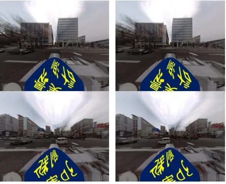
Figure 9. Both middle parts of the resampled stereo panoramic epipolar images with the standard perspective projection. From Figure 8 we can see that all vertical direction parallaxes are eliminated from the resampled panoramic epipolar images, but the scene objects such as buildings are still deformed, and not accustomed to human observation. Since these resampled panoramic epipolar images are two-dimensional plenoptic function can then be re-projected on any type of surface, so we can transfer them into a plane face as a standard perspective
projection. Considering the stereo consequent and the accuracy for 3D measurement of panoramic epipolar images, we remove the worse areas where all the epipolar lines intersect as Figure 5, and select the both middle parts of the base line’s both sides for image matching and stereo viewing. The Figure 9 is one pair of panoramic epipolar images generated under these considerations. As Figure 6, the objects on the bottom part in Figure 9 are opposite to that of the up part on the panoramic epipolar images, and they are not suit for human stereo viewing and object interpretation, so we upturn the bottom part (Figure 10) and make the whole panoramic epipolar images suit for human stereo viewing and object interpretation.
Figure 10. Both middle parts of the resampled stereo panoramic epipolar images with the standard perspective projection.
4. CONCLUSION
Mobile Mapping Systems (MMSs) have become an emerging trend in mapping applications. They allow a task-oriented implementation of mapping concepts at the measurement level. The trend towards MMSs is motivated by the high demand for a fast and cost-effective 3D data acquisition method, and by technological developments in digital imaging, navigation sensors and laser scanners. As the basic sensors of the original MMS prototype, digital cameras are still taking the major role to collect ground images for stereo measurements, fusion with laser point, texture extraction for 3D modelling, ortho-image generation, and site scene view quickly and economically. Since the omni-directional cameras can collect panoramic images of the real environment in one image at field view angle of 360° in longitude direction and 180° in latitude direction, the use of digital panogramic imagery in various geo-related processes has become common over the last decade. Professional applications are found among situational awareness, inventory of public areas, real estate valuation, assessment of permits and inspecting security risks. The demands for large scale visual street-level image database construction by the internet giants such as Google and Microsoft have made the further rapid development of this technology. It’s believe that more and more the imagery is being used for measuring and map making in the future, especially in MMSs.
This paper addresses the problem of panoramic epipolar image generation for 3D modelling and mapping by stereoscopic
viewing. These panoramic images are captured with Point Grey’s Ladybug3 mounted on the top of Mitsubishi MMS-X 220 at 2m intervals along the streets in urban environment. Several projection plans for panoramic epipolar images are selected and the corresponding results are provided. In final, we select two cubic planes along the base line as basic projection planes for panoramic epipolar image generation. The generated panoramic epipolar images are vertical parallax free and can be used for stereo viewing and image matching in 3D retrival.
REFERENCES
Amiri, J. and Gruen, A.,2005. A refined sensor model for panoramic cameras. International Archives of Photogrammetry, Remote Sensing and Spatial Information Sciences, Vol. XXXIV, Part 5/W16.
Chapman, D., Kotowski, R., 2000. Methodology for the Construction of Large Image Archives of Complex Industrial Structures. Publikationen der DGPF, Band 8, Essen 1999. Grejner-Bzezinska, D., 2002. Direct Georeferencing at The Ohio State University: A Historical Perspective, Photogrammetric Engineering and Remote Sensing, 68(6):557-560.
Li,R.X.,1999. Mobile Mapping- An Emerging Technology for Spatial Data Acquisition. The Ohio State University.
Luhmann, T. ,2005. A historical review on panorama imagery, International Archives of Photogrammetry, Remote Sensing and Spatial Information Sciences, Vol. XXXIV, Part 5/W16. Mostafa, M. and K.-P. Schwarz, 2001. Digital Image Georeferencing from Multiple Camera System by GPS/INS, ISPRS Journal of Photogrammetry & Remote Sensing, 56:1-12. Schneider, D., Maas, H.-G. ,2005. Application and accuracy potential of a strict geometric model for rotating line cameras. International Archives of Photogrammetry, Remote Sensing and Spatial Information Sciences, Vol. XXXIV, Part 5/W16.