ACCURATE 3D SCANNING OF DAMAGED ANCIENT GREEK INSCRIPTIONS FOR
REVEALING WEATHERED LETTERS
A. I. Papadaki a, *, P. Agrafiotis a, A. Georgopoulosa, S. Prignitz b a
National Technical University of Athens, School of Rural and Surveying Engineering, Lab. of Photogrammetry Zografou Campus, Heroon Polytechniou 9, 15780, Zografou, Athens, Greece
[email protected], (pagraf, drag)@central.ntua.gr
b
Berlin-Brandenburgische Akademie der Wissenschaften Jägerstrasse 22/23, 10117, Berlin, Germany
Commission V, WG V/4
KEY WORDS: 3D Scanning, Structured Light Scanner, Structure from Motion, Weathered Letters Revealing, Ancient Inscriptions
ABSTRACT:
In this paper two non-invasive non-destructive alternative techniques to the traditional and invasive technique of squeezes are presented alongside with specialized developed processing methods, aiming to help the epigraphists to reveal and analyse weat hered letters in ancient Greek inscriptions carved in masonry or marble. The resulting 3D model would serve as a detailed basis for the epigraphists to try to decipher the inscription. The data were collected by using a Structured Light scanner. The creation of the final accurate three dimensional model is a complicated procedure requiring large computation cost and human effort. It includes the collection of geometric data in limited space and time, the creation of the surface, the noise filtering and the merging of individual surfaces. The use of structured light scanners is time consuming and requires costly hardware and software. Therefore an alternative methodology for collecting 3D data of the inscriptions was also implemented for reasons of comparison. Hence, image sequences from varying distances were collected using a calibrated DSLR camera aiming to reconstruct the 3D scene through SfM techniques in order to evaluate the efficiency and the level of precision and detail of the obtained reconstructed inscriptions. Problems in the acquisition processes as well as difficulties in the alignment step and mesh optimization are also encountered. A meta-processing framework is proposed and analysed. Finally, the results of processing and analysis and the different 3D models are critically inspected and then evaluated by a specialist in terms of accuracy, quality and detail of the model and the capability of revealing damaged and ”hidden” letters.
*
Corresponding author.
1. INTRODUCTION
During the recent years the significant progress in automating the photogrammetric processing and in popularizing close range scanning technology in conjunction with the effective incorporation of computer vision techniques has enabled scientists to capture accurate high resolution data of the three dimensional world and extract valuable information from them. Consequently this advancement has resulted in the evolution of many other research fields while broadening their horizons and modernizing them. For instance, the digital reconstruction of the surface of complex three dimensional objects with real texture and then the visual representation and dissemination of digital information allow the use of three dimensional models as an educational tool by museums (Gonizzi Barsanti and Guidi, 2013, Soile et al., 2013, Wachowiak and Karas, 2009). At the same time, recording and projecting cultural treasures enables the analysis by many different scientists providing them knowledge.
1.1 Related Work
In archaeology and cultural heritage documentation, a very important research field is the study of ancient stone inscriptions. Their documentation is a valuable tool for the
epigraphists, in order to study and -sometimes- decipher them especially when the stone is difficult to read.
1.1.1 Study and Analysis of Ancient Inscriptions: So far, the study and the analysis of ancient inscriptions are mainly based on traditional manual techniques for their geometric documentation and the observations of the naked human eye in front of the stone. The most commonly used method for studying inscribed fragments includes the use of a special type of moisturized paper (squeeze) pressed into the stone, through which they attempt to create an impression of the surface of the inscription (Woodhead, 1992). Other materials used in the literature for the above process are latex or liquid rubber (Beck, 1963). Although the squeezes method produces reliable copies of inscribed surfaces, there are several drawbacks and problems that may rise during their use like the limited accessibility by many researchers, their preservation through time and their restrictive use in over-weathered surfaces. In some instances it is even not allowed to touch and tamper with the inscriptions, as they may be extremely fragile.
capturing under different lighting directions and camera viewpoints (Malzbender et al., 2001), video sequence or a set of 2D images for reconstructing a three dimensional scene (Lerma and Muir, 2014, Cornelis et al., 2001). However, the precision and detail of the obtained reconstructions is often not high enough for capturing details on inscribed surfaces such as letters and symbols. This is especially the case when the inscriptions are weathered and practically illegible. Other more sophisticated methods use laser scanners (Lerma and Muir, 2014, Landon and Seales, 2006), devices that can capture in a very detailed way the inscribed surface. A more cost-effective method that requires only the squeezes is presented by Barmpoutis et al. (2010). Through the aforementioned methods the epigraphists are called to answer questions and make decisions on specific issues including the ascription of fragments, the dating of the inscriptions, the identification of the place of origin, the identity of the letter cutter and the analysis of the lettering techniques. For the methods and the results presented in this paper, we have documented ancient Greek inscriptions carved in masonry or marble from Parthenon Inventory Lists written after 403 BC and we present extensive experimental results from their 3D reconstruction and their analysis.
1.1.2 Outline: The rest of the paper is outlined as follows. In Section 2, is presented the Data Acquisition Methodology including a detailed object's description. Section 3 is divided into several subsections describing the data processing steps that have been followed and the results (mesh generation and alignment in Sect. 3.1, meta-processing and analysis of 3D models along with the results and the evaluation presentation in Sect. 3.2). In Section 4 we conclude while in Section 5 we present our future work.
2. DATA ACQUISITION METHODOLOGY
2.1 Object's Description
Traditiones Parthenonis (handing over lists of the Parthenon) were inventory lists for the items stored in the Parthenon on the Athenian Acropolis. The magistrates of the Athenian democracy began in 434/3 BC, after the Parthenon was complete, to give accounts for the treasures of the Parthenon and Erechtheion. The lists with the items were inscribed on large stones, partially up to 2 m high and over 1 m wide, and stood on the Acropolis so that the accounts could be visible for the public. The last inventories were written around 300 BC. Later, when the stones came out of their primary context, they were reused as thresholds, doorposts and masonry blocks, sometimes they were recut for the secondary use or they fell down and broke. inscriptions, published since 1815 by the Berlin Academy of Sciences. The Parthenon inventories written before 403 BC are published in IG I³ 292-362 (volume from 1981), the inventories after 403 BC in IG II² 1370-1513 (volume from 1927).
secondary use and is now stored in the Epigraphic Museum of Athens (inv. 7856/7). The account contains, as the other sides to inscribe the complete text on one block of marble. Thus on the backside of the aforementioned stone, there is also text. There is even one more column of text than it was published in the last complete edition of 1927; but the letters of this fifth and last column are very faint and hardly readable. Therefore, as the first four columns of text are preserved relatively well and as this kind of text (lists) is – compared to other kinds of text – more “predictable” in its content, the unpublished column of text from the backside of this stone was our choice for 3D scanning.
2.2 Accurate 3D model Creation
The procedures applied and described below involve the 3D scanning of the inscriptions using image based techniques as the use of laser would deteriorate the accuracy. These involve the use of a Structured Light Scanner and Structure from Motion techniques. Since the use of structured light scanners is time consuming and requires costly hardware and software the alternative and cost/time effective SfM methodology for collecting 3D data of the inscriptions was also implemented for reasons of comparison. The result was the creation of an accurate 3D surface model, which would serve as a detailed basis for the epigraphists to try to decipher the inscription. This 3D model should preferably be non-coloured, i.e. without photographic texture in order not to mislead the archaeologists from misunderstanding and misinterpreting of the anaglyph.
2.2.1 Structured Light Scanner: As already stated, Structured Light Scanners are an alternative to laser scanners. In order to geometrically document the inscriptions, data were collected by using a Structured Light scanner (SL2 by RGBXYZ Inc.) consisting of two machine vision cameras (5MP) and a standard DLP projector.
the determination of its geometry, while the DLP projector was projecting the structured light patterns. These patterns are alternating black and white stripes with decreasing width. The two cameras were mounted on a rigid base with the distance between them being approximately equal to one third of the cameras to object distance. The maximum density capability equals to 150m and the maximum precision to 50m, according to the manufacturer (Georgopoulos et al., 2010). This specific model of structured light scanner, though, is slightly differentiated from the traditional structured light approach, mentioned above, as it consists of two cameras; the three dimensional coordinates are computed by triangulation between corresponding optical rays from the two machine vision cameras and not by triangulation between a ray and a plane. For achieving accurate and reliable results, a necessary setup calibration was applied. By this procedure are determined the interior orientation parameters of the cameras, their relative position and the scale of acquisition. For this purpose a custom calibration board, a simple checkered board, is imaged at various angles by both cameras (Figure 1).
Figure 1. System’s Calibration Step
Intrinsic parameters of left camera:
Focal Length: fc_left = [ 3957.24341 3959.76799 ] Principal point: cc_left = [ 606.10432 521.37367 ] Skew: alpha_c_left = [ 0.0000 ]
Distortion: kc_left = [ 0.13144 1.36164 0.00169 -0.00320 0.00000 ]
Intrinsic parameters of right camera:
Focal Length: fc_right = [ 3971.39481 3973.44483 ] Principal point: cc_right = [ 638.80226 473.48252 ] Skew: alpha_c_right = [ 0.00000 ]
Distortion: kc_right = [ 0.12822 1.52410 0.00051 -0.00138 0.00000 ]
Extrinsic parameters (position of right camera wrt left camera):
Rotation vector: om = [ -0.00958 0.43170 0.02699 ] Translation vector: T = [ -264.56873 -1.25983 64.33251 ]
Figure 2. The Structured Light system setup (Left) and an individual scan example (Right)
For the scanning of the inscriptions described in this paper, the system was placed at no more than 50cm from the inscription, having the capability of scanning 50-60cm2 at a time (Figure 2 Left). Hence, 80 individual scans (Figure 2 Right) were performed considering a constant horizontal and vertical overlap of about 30%. In addition, the determination of the suitable imaging parameters of the two machine vision cameras was very crucial in order to acquire the data with best quality. The most well-known of these were pixel clock and exposure, which are related to the refresh rate of the pixels on the screen and the amount of light allowed falling on the photographic sensor.
2.2.2 Structure from Motion (SfM): SfM has a flexible camera model until calibration parameters are added to the workflow being used (Chandler and Fryer, 2013; Crandall et al., 2013). Through this procedure, a 3D point cloud could be generated assuming the matching overlap in a group of photographs. SfM can generate a 3D point cloud based on images taken from multiple viewpoints, otherwise known as Multi View Stereo (MVS), and corresponding geometry of shapes within a scene (Snavely et al., 2006; Crandall et al., 2013; Koutsoudis et al., 2013). For this approach, image sequences from varying distances were collected using a calibrated professional Canon EOS-1Ds Mark III full frame digital camera (5616x3744 pixels and 6.4μm pixel size) aiming to reconstruct the 3D scene through structure from motion (SfM) techniques in order to evaluate the efficiency and the level of precision and detail of the obtained reconstructed inscriptions.
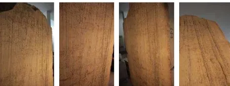
Figure 3. Some of the images used for the SfM procedure
A 24mm wide angle lens was used due to the small camera-to-object distance. The aforementioned characteristics lead to an average GSD of 120μm. 57 normal and slightly convergent RAW and JPEG images were acquired setting the sensitivity to a normal value, ISO 200. An approximate mean distance of 0.30m was used for the shots, fixing manual focus. As the data acquisition was an indoor process, a tripod was used to get non-blur images. The software used for this procedure was PhotoScan® by Agisoft.
2.3 Difficulties in the acquisition processes
machine vision cameras of the Structured Light Scanner. In these cases the scanned surface was not a rectangle like the one presented in Figure 1b but a trapezium or another projection of the rectangle leading to occlusions. Finally, the illumination did not add any problems, due to the homogeneity in the colours of the object itself.
3. DATA PROCESSING AND RESULTS
The creation of the final accurate three dimensional model is a complicated procedure requiring large computation cost and human effort. It includes the collection of geometric data in limited space and time, the creation of the surface, the noise filtering and the merging of individual surfaces. It is important to note that in such cases, the detail of the surface may indicate the existence of a weathered letter, thus the noise filtering must be a carefully implemented procedure. The products of the scanning procedure were processed using various software packages, for the production of the final accurate 3D models of the inscriptions. In order to automate the various steps of the procedure and to achieve better results, various software, commercial and not, were combined. In the following the individual steps of this procedure and the used software are given.
3.1 Mesh Generation and Registration
3.1.1 Structured Light Scanner Data:In this section, the mesh generation procedure and their alignment is described for Structured Light Scanner data. The result of each scan is a point cloud. Each point cloud is triangulated into a dense (up to 150μm) mesh of triangles, with points on the objects surface, using Delaunay triangulation. The results from each individual scan are the mesh, which is exported in OBJ format for further processing, and an image in JPG format, which is responsible for the texture information. Initially, the aforementioned exported individual meshes were inserted in Geomagic Studio® for the registration and merging procedure, since each mesh refers to a different local system as well as for holes filling and noise filtering. For the meshes registration a combination of manual and automatic techniques was applied. After selecting 3 or more common points in unregistered meshes, the registration is made.
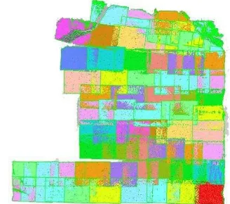
Figure 4. Individual scans after the registration process
Then, the ICP (Chen and Medioni, 1991) algorithm was used in order to refine the results of the manual registration. Through the manual step, values are calculated for the transformation, which are then optimised. Having completed the registration of
all meshes, the final surface is processed as a whole and all the individual meshes are extracted separately in OBJ format so as to be georeferenced.
3.1.2 Structure from Motion (SfM) Data: In this section, the image alignment and mesh generation procedure is described for Structure from Motion (SfM) data. The necessary procedures were realized through the use of Agisoft’s PhotoScan® software. Initially and after loading the photos, the calibration parameters of the system camera-lens were inserted. Subsequently, these photos need to be aligned. At this stage PhotoScan® finds the camera position and orientation for each photo and builds a sparse point cloud model. Alignment having been completed, computed camera positions and a sparse point cloud were displayed.
Figure 5. Reconstructed Mesh from Agisoft’s Photoscan®
After an inspection of the alignment results, the generation of the dense point cloud model took place. At this stage, the program, based on the estimated camera positions calculates depth information for each camera to be combined into a single dense point cloud. At this stage, the desired reconstruction quality was specified as "ultra high" in order to obtain more detailed and accurate inscription surface (Figure 5). Due to some factors, like poor texture of some elements of the scene, noisy or badly focused images, there can be some outliers among the points. To sort out the outliers, several built-in filtering algorithms are applied. Since texture is not required in such applications in order not to mislead the archaeologists from misunderstanding and misinterpreting of the anaglyph, a generic texture mapping was applied for better visual quality of the final model and navigation through it. This Generic mapping mode allows the parameterization of texture atlas for arbitrary geometry. No assumptions regarding the type of the scene to be processed are made as well as the software tries to create as uniform texture as possible.
3.2 Meta-Processing of 3D Models and Results Analysis
3.2.1 3D Model Selection: The resulting 3D models were visually inspected for their detail in letters description and mapping. The results indicated that the most suitable 3D model for the revealing of the weathered letters in the scanned inscriptions is the one created using the structured light scanner data. To this decision leads the fact that the 3D model created by the structured light scanner data depicts the letters in a more detailed way and this offers the capability of revealing better and more accurate "hidden" and destroyed letters (Figure 6).
Figure 6. Resulting surface from Structured Light data (Left) and SfM data (Right)
However, the implemented alternative methodology of SfM for collecting 3D data of the inscriptions has shown very promising results and further research in its implementation is planned at a later stage.
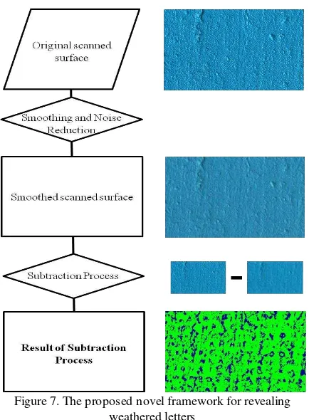
3.2.2 The Meta-processing Framework:In order to reveal the weathered letters, an efficient and easy to use from the epigraphists framework was developed and implemented requiring a minimal computational cost (Figure 7). The key idea for developing this framework is to smooth and normalize the surface model of this part of the already weathered inscription and then subtract it from the original scanned surface.
Figure 7. The proposed novel framework for revealing weathered letters
By this innovative procedure, any alterations of the original surface from the smoothed one will be a carving indicating a
letter of a damaged part of the masonry. In that way, variations in the surface of inscription which are not recognized by the human eye are highlighted. Key point of this process is the level of the smoothing procedure as well as the threshold of the meshes subtraction. For this paper, the described framework was implemented through the use of commercial software leaving no possibilities to control all the parameters involved such as the smoothing algorithm and the subtraction process.
3.2.3 Results and Analysis of the Meta-processing: Figure 8 presents a non-weathered part of the scanned inscription while Figure 9 an extremely weathered part of the same inscription.
(a)
(b)
(c)
Figure 8. Textured (a) and non-textured (b) reconstructed surface of a non-weathered Parthenon Inventory List. (c)
revealed letters as a result of processing
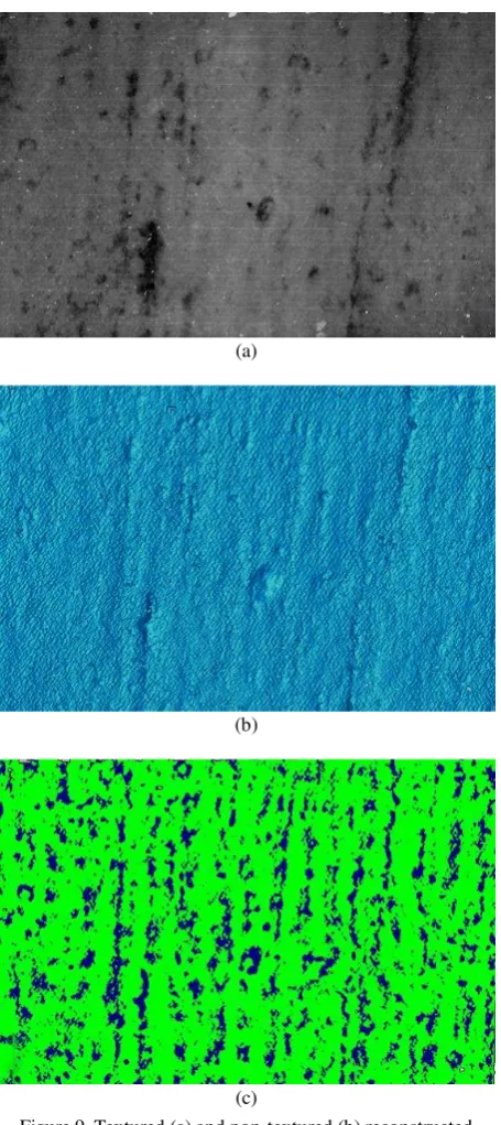
non-textured model (8b), the processed model (8c) and even in the textured model (8a). On the other hand, the textured and non-textured surface model on the pre-processing stage of an extremely weathered scanned part of the inscription, that are presented in Figure 9a and 9b respectively, make it clear that it is impossible for the archaeologists to observe horizontal and vertical rows of letters in order to analyse them. However, as it is observed in Figure 9, after meta-processing, can be recognized the stoichedon order (the letters are standing not only in horizontal lines, as usual in any inscription, but also in vertical rows) and some Omicrons are clearly obvious.
(a)
(b)
(c)
Figure 9. Textured (a) and non-textured (b) reconstructed surface of a very weathered Parthenon Inventory List. (c)
revealed letters as a result of processing
3.2.4 Evaluation from an Expert: It is obvious that this novel proposed framework helps the epigraphists to follow the order
of the letters both in horizontal and vertical direction. In addition, through this procedure, letters are appearing on weathered surfaces like the one presented in Figure 9. The results of this first attempt to deal with 3D models are encouraging. The chosen study area of the inscription is one of the most difficult tasks for deciphering: A column of text so weathered that it was not even recognized as a text column up to now. After the additional column was recognized, the first deciphering was done in front of the stone with a strong light. This version was now checked on screen with the 3D model. After meta-processing (Figure 9c), experts could already clearly see that (a) The whole area was once inscribed, and (b) that it was inscribed in the same stoichedon order as the other four columns of text.
With bare eyes and light, it was clear that there are some letters and that they comply with the size and the letter forms of the first four columns, but the electronic version shows traces of much more letters (even if not to decide which letter it has been in all instances), and even the whole stoichedon order that could be guessed but not assured with bare eyes. The proposed framework of meta-processing should be refined now in collaboration of 3D specialists and epigraphists.
For the revealing of up-to-now “hidden” letters by using the mesh, it was not only possible to recover the letters that were seen with the epigrapher’s bare eyes, but also to make progress. This is mainly that we can better distinguish between letter and mere injury of the stone: one of the greatest problems in epigraphy is, in cases of badly preserved stones, whether an indentation is a casual cut in the marble or the trace of the letter cutter’s chisel. An additional problem is colour change on the original stone that hinders the clear view. On a traditional squeeze, there are no different colours and in the imprint it can be better seen whether a trace comes from a chisel or not, but there are other issues, e.g. that a squeeze cannot be magnified. With a 3D model, the colour problem can also be dropped out, and by playing with the direction of light on screen, it can be better decided whether the cut is a regular cut done by a chisel or an irregular injury, like with turning a paper queeze around under a lamp. Additionally, the 3D model can be magnified. And it has to be emphasized again that it is possible to make a scan in cases of fragile surfaces where the production of a squeeze with its necessary mechanical pressure is perhaps sometimes inadvisable.
4. CONCLUSIONS
In this paper two non-invasive non-destructive alternative techniques to the traditional and invasive technique of squeezes are presented alongside with specialized developed processing methods, aiming to help the epigraphists to reveal and analyse weathered letters in ancient Greek inscriptions carved in masonry or marble.
scanner data, although time and effort consuming procedure. Consequently, an innovative meta-processing framework was developed and implemented on this model, consisting of subtracting a smoothed and normalized surface model from the originally scanned surface.
Through the presented techniques, is performed the acquirement of an accurate 3D Model of the inscription, which offers the capability of digitally storing of all the supplied information, even this which is not obvious with a bare eye. This fact as well as the non-invasive character of the presented techniques, offer the possibility not only of prevention from any damage, but also of accessibility, time and locality independent study, analysis and processing of any type of inscriptions, even the very weathered ones. Another contribution of the presented framework is the innovative meta-processing procedure that was developed through which the lettering schemes are efficiently recognized. The final product can be easily handled, is time saving and really reliable for accurate scientific conclusions and deciphering of inscriptions.
The proposed framework was applied to an ancient Greek inscription concerning the inventory of the Parthenon. The results of processing and analysis were inspected and evaluated by a specialist in terms of detail, accuracy and quality of the model, as well as the capability of revealing damaged or “hidden” letters and finally deciphering the inscription.
5. FUTURE WORK
Our future work, will include a further study and analysis on the proposed novel framework for revealing weathered letters. In more detail, state of the art smoothing algorithms will be implemented in order to evaluate the reliability and the accuracy of the results. Moreover, a future goal is the system to automatically calculate the parameters of the smoothing level according to the surface anaglyph and remaining letters' depth. Finally, the SfM technique will be further developed, in order to take advantage of its promising results.
ACKNOWLEDGEMENTS
The research leading to these results has been supported by European Union funds and National funds (GSRT) from Greece and EU under the project 3D ORO: Efficient and Effective 3D Computer Vision Tools for Improving the Performance of 3D Digitalization funded under the cooperation framework.
We also want to acknowledge for permission for scanning the Epigraphical Museum of Athens (Athanasios Themos and Elena Zavvou) and Prof. Constantin Papaodysseus and Dr. Athanasios Panagopoulos for their scientific cooperation.
REFERENCES
Barmpoutis, A., Bozia, E. and Wagman, R. S., 2010. A novel framework for 3d reconstruction and analysis of ancient inscriptions. Machine Vision and Applications, Vol. 21(6), pp. 989–998.
Beck, C. W., 1963. Synthetic elastomers in epigraphy. American Journal of Archaeology pp. 413–416.
Chandler, J., Fryer, J., 2013. Autodesk 123D catch: how accurate is it? Geomatics World, Vol. 2 (21), pp. 28-30
Chen, Y., & Medioni, G. (1992). Object modelling by registration of multiple range images. Image and vision computing, Vol. 10(3), 145-155.
Cornelis, K., Pollefeys, M., Vergauwen, M. and Van Gool, L., 2001. Augmented reality using uncalibrated video sequences. In: 3D Structure from Images SMILE 2000, Springer, pp. 144–160.
Crandall, D., Owens, A., Snavely, N., Huttenlocher, D., 2013. Discrete-continuous optimization for large-scale structure from motion. IEEE Trans. Pattern Anal. Mach. Intell. (PAMI). http://www.cs.indiana.edu/~djcran/papers/disco13pami.pdf (accessed 21.01.15).
Georgopoulos, A., Ioannidis, C. and Valanis, A., 2010. Assessing the performance of a structured light scanner. In: Commission V Symposium. International Archives of Photogrammetry, Remote Sensing and Spatial Information Sciences, Vol. 38(5), Citeseer.
Gonizzi Barsanti, S. and Guidi, G., 2013. 3d digitization of museum content within the 3dicons project. ISPRS Annals of Photogrammetry, Remote Sensing and Spatial Information Sciences II-5/W1, pp. 151–156.
Koutsoudis, A., Vidmar, B., Ioannakis, G., Arnaoutoglou, F., Pavlidis, G., Chamzas, C., 2013. Multi-image 3D reconstruction data evaluation. J. Cult. Herit., Vol. 15 (1), 73-79.
Landon, G. and Seales, W., 2006. Petroglyph digitization: enabling cultural heritage scholarship. Machine Vision and Applications, Vol. 17(6), pp. 361–371.
Lerma, J. L. and Muir, C., 2014. Evaluating the 3d documentation of an early christian upright stone with carvings from Scotland with multiples images. Journal of Archaeological Science, Vol. 46, pp. 311–318.
Malzbender, T., Gelb, D. and Wolters, H., 2001. Polynomial texture maps. In: Proceedings of the 28th annual conference on Computer graphics and interactive techniques, ACM, pp. 519– 528.
Snavely, N., Seitz, S.M., Szeliski, R., 2006. Photo Tourism: Exploring Photo Collections in 3D. http://phototour.cs. washington.edu/Photo_Tourism.pdf (accessed 21.01.15).
Soile, S., Adam, K., Ioannidis, C. and Georgopoulos, A., 2013. Accurate 3d textured models of vessels for the improvement of the educational tools of a museum. ISPRS-International Archives of the Photogrammetry, Remote Sensing and Spatial Information Sciences, Vol. 1(1), pp. 211–217.
Wachowiak, M. J. and Karas, B. V., 2009. 3d scanning and replication for museum and cultural heritage applications. Journal of the American Institute for Conservation, Vol. 48(2), pp. 141–158.