Perancangan Pengendalian
Proses Pabrik
07
Mempelajari perancangan alternatif-alternatif konfigurasi
pengendalian untuk proses multi-input-multi-output pada pabrik
1. Tinjauan Umum Pengendalian Proses MIMO 2. Derajat Kebebasan
3. Penentuan Konfigurasi Loop Alternatif
4. Pengendalian Proses dengan Interaksi Unit-Unit
5. The Nine Steps of Plantwide Process Control Procedure
Tujuan:
7.1 Tinjauan Umum Pengendalian
Proses MIMO
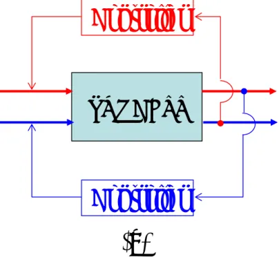
Tinjau Proses dengan beberapa input & output:
PROCESSING SYSTEM . . . Measured (d) . . . Unmeasured (d′) External Disturbances . . . Manipulated Variables (m) Input . . . Unmeasured Outputs (z) . . . Measured Outputs (y)
7.1 Tinjauan Umum Pengendalian Proses MIMO
Pertanyaan yang harus dijawab sebelum merancang sistem
pengendalian:
1. Apa tujuan pengendalian? Berapa jumlah CV? & yang mana? 2. Output apa yang harus diukur? Primer? Atau Sekunder?
3. Input apa yang dapat diukur? Primer? Atau Sekunder?
Jika diasumsikan semua MV dapat diukur, maka dapat diterapkan adaptive & Inferential Control.
Disturbance: hanya sedikit yang dapat diukur, maka dapat diterapkan FFC-FBC, Ratio Control.
4. MVapa yang harus dipilih?
5. Konfigurasi loop pengendalian apa yang digunakan?
Sistem MIMO, menghasilkan banyak alternatif konfigurasi pengendalian
7.2 Derajat Kebebasan
Degree of Freedom (DOF)
DOF = V – E
… (7.2.1)Dimana: V = Jumlah Variabel Bebas
E = Jumlah Persamaan Bebas; hubungan antar V Perancangan Pengendalian: DOF = 0 Æ V = E
Bermanfaat dalam penentuan jumlah controlled variables (CV) dan jumlah manipulated variables (MV)
Dua pers. tambahan untuk menurunkan DOF menjadi nol:
1. Pengaruh eksternal:
(a) lingkungan yang mempengaruhi sistem operasi, (b) unit upstream sebagai umpan proses,
(c) unit downstream (bila outflow proses adalah inflow yang dimanipulasi untuk unit downstream)
7.2 Derajat Kebebasan
2. Sistem Pengendalian:
→ korelasi: MV & CV (FBC) MV & d (FFC)
→ Jumlah CV = DOF – Jumlah Input Eksternal … (7.2.2)
Berapa banyak MV yang diperlukan untuk menjaga
output (CV) pada nilai yang diinginkan (setpoint)?
7.2 Derajat Kebebasan
Tinjau proses dengan spesifikasi sebagai berikut:
N : output yang dikendalikan (y1, y2, … , yN)
M : manipulasi bebas (m1, m2, … , mM) dengan M ≥ N L : jumlah gangguan eksternal (d1, d2, … , dL)
Anggap: N persamaan hubungan y, m, dan d adalah sbb:
y1 = f1 (m1, m2, … , mM ; d1, d2, … , dL) y2 = f2 (m1, m2, … , mM ; d1, d2, … , dL)
yN = fN (m1, m2, … , mM ; d1, d2, … , dL)
… … (7.2.3)
Dengan perubahan d, nilai y harus tetap: hal ini mungkin jika N dari M buah MV dapat diubah secara bebas.
Untuk Perancangan Pengendalian:
Jumlah MV bebas = Jumlah CV = DOF – Jumlah Input Eksternal … (7.2.4) Catatan-Catatan:
1. Tinjau pers. (7.2.2); Jika jumlah CV = k buah, & CV nyata = l & l < k.
Jumlah var. yang tidak dikendalikan = (k – l) buah; hal ini dapat
menyebabkan masalah, namun bila pengaruhnya dapat diterima pada operasi proses, maka logis untuk mpy CV < pers. (7.2.2).
2. TIDAK MUNGKIN merancang sistem pengendalian yang dapat mengatur CV melebihi CV pada pers. (7.2.2).
3. DOFdinamik ≥ DOFtunak
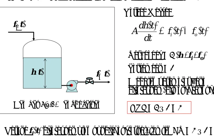
Contoh 7.2.1: DOF pada sistem tangki cairan (Gambar 7.2.1) Neraca Massa:
)
(
)
(
)
(
t
f
t
f
dt
t
dh
A
=
i−
o Var. bebas = 3 (h , fi , fo) Persamaan = 1A adalah parameter yang ditetapkan (dimensi tangki)
DOF = 3 – 1 = 2
Karena fi(t) ditetapkan oleh kondisi eksternal, jumlah CV = 2 – 1 = 1
Feedback loop antara h dan fo
7.2 Derajat Kebebasan
fi(t)
fo(t) h(t)
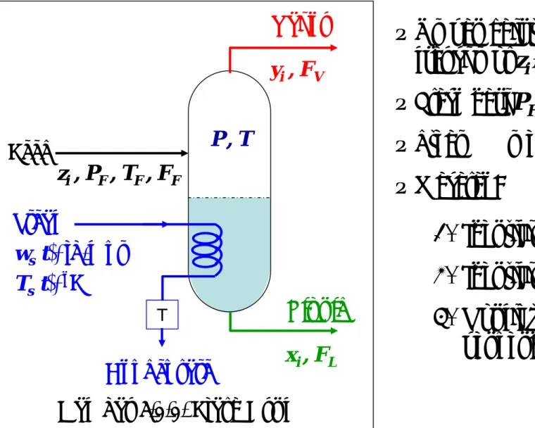
Contoh 7.2.2: Menentukan jumlah CV dan MV untuk flash drum
• Umpan cair t.d.d. N komponen fraksi mol ziÆ i = 1,2,…,N
• Flash dari PF ke P → PF >> P • Steam → menjaga T tetap
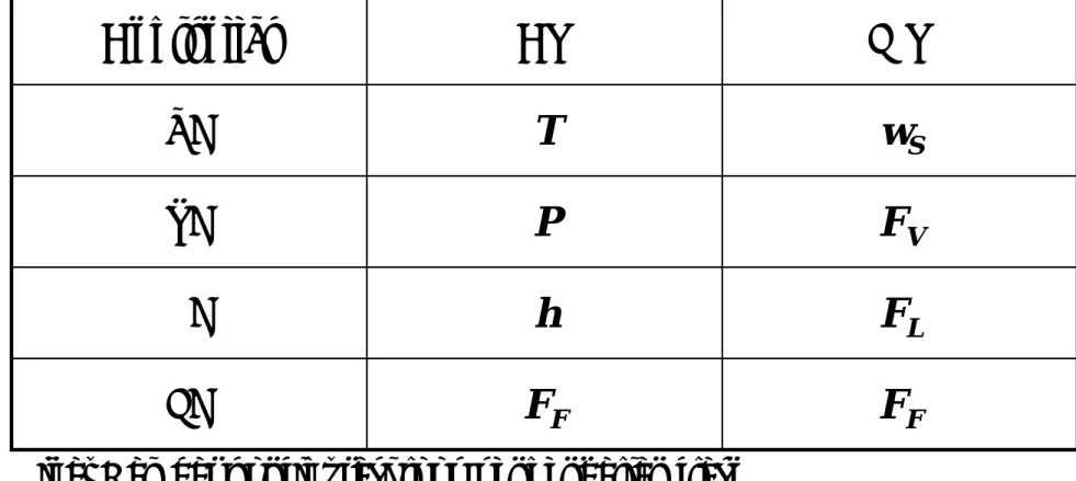
• Masalah: 1. Identifikasi CV 2. Identifikasi MV 3. Konfigurasi loop pengendalian 7.2 Derajat Kebebasan Steam T Condensate Liquid Feed zi , PF , TF , FF xi , FL ws(t), lb/mnt Ts(t), oF Vapor yi , FV P , T
Penyelesaian Soal 7.2.2:
7.2 Derajat Kebebasan
Neraca Massa Total (asumsi ρ konstan)
( )
(
)
i L i V i F ix
F
y
F
z
F
dt
x
h
d
A
ρ
.
=
.
−
.
+
.
( )
(
)
(
)
T
T
UA
T
F
Cp
T
F
Cp
T
F
Cp
dt
T
h
d
A
Cp
L.
=
F F F−
V V+
L L+
S S−
(
V L)
FF
F
F
dt
dh
A
ρ
=
−
+
Neraca Massa Komponen
Dimana i = 1,2, …, N – 1
Eq. = 1
Eq. = N – 1
Neraca Panas
Penyelesaian Soal 7.2.2 (lanjutan): 7.2 Derajat Kebebasan
∑
∑
= ==
=
N i i N i idan
y
x
1 11
1
(
)
i i iK
T
P
x
y
=
,
Batasan Dimana i = 1,2, …, NHubungan Kesetimbangan Vapor-Liquid
Eq. = N
Eq. = 2
Jumlah Persamaan:
Penyelesaian Soal 7.2.2 (lanjutan): 7.2 Derajat Kebebasan • Konstan: Jumlah Variabel A , AS , ρ , U , CpF , CpV , CpL = 7 Ki(T,P) = N Subtotal 1 = N + 7 • Eksternal yg ditentukan : TF = 1 zi = N – 1 Subtotal 2 = N • Eksternal yg tidak ditentukan : FF , FV , FL , P , T , h , Ts (atau wS) = 7 xi , yi (untuk i = 1, 2, …, N) = 2N Subtotal 3 = 2N + 7 Jumlah Variabel: V = N+7 + N + 2N + 7 = 4N + 14
Penyelesaian Soal 7.2.2 (lanjutan):
7.2 Derajat Kebebasan
DOF = V – E = (4N + 14) – (2N + 3) = 2N + 11
Jumlah variabel eksternal yg ditentukan = N + 7 + N = 2N + 7 Jumlah MV = Jumlah CV = DOF – Jumlah Input Eksternal
= (2N + 11) – (2N + 7) = 4
Dipilih 4 CV dari (2N + 7) “unspecified variables”
9 T dan P untuk mendapatkan pemisahan yang diinginkan 9 FF untuk mendapatkan produksi tetap
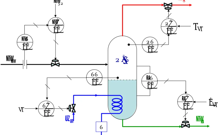
Gambar 7.2.3. Konfigurasi Pengendalian Proses Flash Drum (Lengkap dengan sistem sensor/transmitter)
7.2 Derajat Kebebasan T FF FL ws FV P , T FT 10 FC 10 FSP LT 10 LC 10 hSP PT 10 PC 10 PSP TT 10 TC 10 TSP
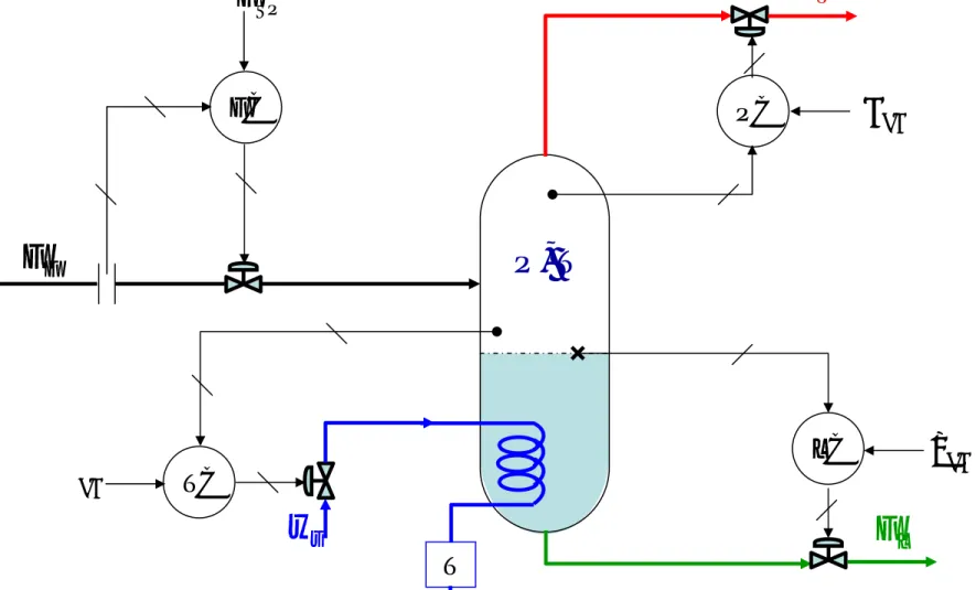
Gambar 7.2.4. Penyederhanaan Gambar Konfigurasi Pengendalian Proses Flash Drum (Contoh 7.2.2)
7.2 Derajat Kebebasan T FF FL ws FV P , T FC FSP hSP PSP TSP TC PC LC
7.3 Penentuan Konfigurasi
Loop Alternatif
Untuk Sistem dengan N CV dan N MV
¾Terdapat sekitar N! konfigurasi loop yang berbeda
¾Misal, CV = 2 ; MV = 2 ; Konfigurasi Loop = 2 ! = 2 x 1 = 2 ¾Lihat Gambar Konfigurasi Loop Alternatif untuk proses 2 x 2 ¾Jika N = 3 Konf. Loop = 3 ! = 6
N = 4 Konf. Loop = 4 ! = 24 N = 5 Konf. Loop = 5 ! = 120
Gambar 7.3.1. Konfigurasi Loop Alternatif Proses 2 x 2
PROCESS Controller Controller y1 y2 m1 m2 PROCESS Controller Controller y1 y2 m1 m2 (a) (b)7.3 Penentuan Konfigurasi Loop Alternatif
Kriteria Pemilihan Konfigurasi Loop Alternatif
Secara Kualitatif:
1. Pilih MV yang mempunyai efek langsung dan cepat terhadap CV
2. Pilih pasangan MV dan CV yang memberikan time delay (td) sekecil mungkin
3. Pilih pasangan MV dan CV dengan interaksi loop-loop pengendali sekecil mungkin
Secara Kuantitatif (tidak dibahas dalam MKA ini)
1. Teknik Singular Value Decomposition (SVD) 2. Teknik Relative Gain Array (RGA)
7.3 Penentuan Konfigurasi Loop Alternatif
Contoh 7.3.1: Menentukan konfigurasi loop alternatif untuk flash drum secara kualitatif
Tinjau kembali Contoh 7.2.2:
MV = 4 ; CV = 4 Æ Konfigurasi Loop = 4 ! = 4 x 3 x 2 x 1 = 24 CV ≡ FF , P , T , h
MV ≡ FF , FL , wS , FV Bagaimana konfigurasi loop yang mungkin?
Penyelesaian:
1. Susun Kemungkinan Konfigurasi Loop Alternatif
2. Eliminasi beberapa Alternatif berdasarkan analisis kualitatif 3. Pilih Alternatif terbaik (satu diantara kemungkinan yang ada)
7.3 Penentuan Konfigurasi Loop Alternatif
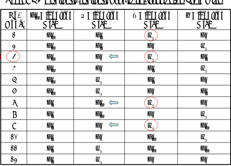
Tabel 7.3.1 Alternatif-alternatif konfigurasi loop untuk Flash Drum
12 FF FF wS FL 11 wS FF FV FL 10 FF wS FV FL 9 wS FV FF FL 8 FV wS FF FL 7 FL FV wS FF 6 FV FL wS FF 5 wS FL FV FF 4 FL wS FV FF 3 wS FV FL FF 2 FV wS FL FF 1 h Dikontrol Oleh T Dikontrol Oleh P Dikontrol Oleh FF Dikontrol Oleh No. Konf. best
7.3 Penentuan Konfigurasi Loop Alternatif Tabel 7.3.1 Lanjutan FL FF FV wS 23 FF FV FL wS 22 FV FF FL wS 21 FL FV FF wS 20 FV FL FF wS 19 FF wS FL FV 18 wS FF FL FV 17 FF FL wS FV 16 FL FF wS FV 15 FL wS FF FV 14 wS FL FF FV 13 h Dikontrol Oleh T Dikontrol Oleh P Dikontrol Oleh FF Dikontrol Oleh No. Konf.
7.3 Penentuan Konfigurasi Loop Alternatif
Argumentasi kualitatif untuk memilih konfigurasi loop alternatif terbaik:
1. Pengaruh FF, FV, dan FL terhadap T adalah tidak langsung dan lambat, sedangkan wSberpengaruh langsung dan cepat terhadap T.
→ pilih No. konf : 1 , 3 , 7 , 9 , 14 , dan 18
2. Pengaruh wS dan FL terhadap P adalah tidak langsung dan lambat. FF dan FV adalah MV yang baik untuk P.
→ dari seleksi pertama, pilih No. konf. : 3 , 7 , 9 , dan 14 3. Dari No. konf. : 3 , 7 , 9 , dan 14 ; 3 adalah yang terbaik, karena:
9 FL cepat untuk mengendalikan level (h)
7.3 Penentuan Konfigurasi Loop Alternatif
Berdasarkan argumentasi kualitatif, diperoleh konfigurasi loop:
F
FF
FFC
F
Lh
LC
F
VP
PC
w
ST
TC
MV
CV
Controller
Lihat Gambar konfigurasi loop pengendalian flash drum pada Contoh 7.2.2 !
Tinjau proses yang disusun dari N unit yang berinteraksi satu dengan yang lain melalui aliran massa dan energi.
Prosedur sistematik untuk menentukan konfigurasi pengendalian untuk keseluruhan proses:
1. Kelompokkan proses menjadi blok-blok terpisah, dimana tiap blok berisi satu unit pemisah atau sejumlah kecil unit pemroses.
2. Tentukan DOF, jumlah CV dan MV untuk tiap-tiap blok.
3. Tentukan semua loop konfigurasi yang mungkin untuk tiap blok 4. Gabungkan kembali blok-blok dengan loop konfigurasinya.
5. Eliminasi konflik/pertentangan diantara sistem kendali dari berbagai blok
7.4 Pengendalian Proses dengan
Interaski Unit-Unit
7.4 Pengendalian Proses dengan Interaksi Unit-Unit
Contoh 7.4.1: Konflik loop kendali pada unit-unit proses
Unit 1 Unit 2
Unit 1 Unit 2
Konflik
Controller
Controller
Gambar 7.4.2. Konflik loop pengendalian pada 2 unit-proses-seri
7.4 Pengendalian Proses dengan Interaksi Unit-Unit
Gambar 7.4.2. Lanjutan
7.4 Pengendalian Proses dengan Interaksi Unit-Unit
Unit 1 Konflik Controller Unit 2 Controller (b)
7.4 Pengendalian Proses dengan Interaksi Unit-Unit
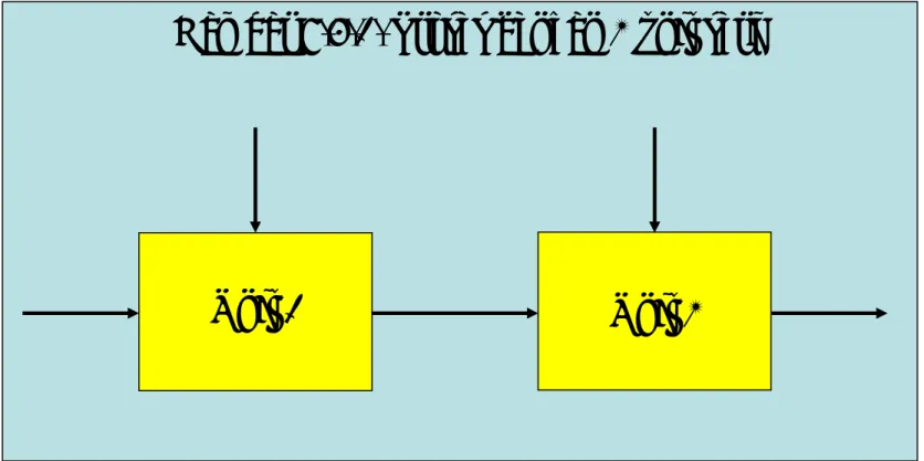
Contoh 7.4.2: Membangun konfigurasi loop pengendalian untuk proses kimia sederhana (Lihat Gambar 7.4.2).
Penjelasan proses:
Reaksi A → B eksotermis dilaksanakan dalam CSTR dengan pendingin jaket. Umpan reaktor dipanaskan awal memakai hasil reaksi dan steam. Pendingin dicabang dua, dilengkapi dengan pemanas dan pendingin (Qh dan Qc). Hasil reaktor didinginkan di HE dan dipisahkan dalam flash drum. Suhu drum diatur dengan pendingin air.
Tujuan operasi:
1. Menjaga konversi reaktor sebesar mungkin 2. Menjaga laju produksi tetap
Reactor A Æ B
7.4 Pengendalian Proses dengan Interaksi Unit-Unit
Heating Coolant Cooling Coolant system Feed Steam Feed preheating Flash drum FC, TCO Fi, TO Fi, Ti , CAi Fi, TR , CA Vapor Liquid Tf, Pf Cooling water
7.4 Pengendalian Proses dengan Interaksi Unit-Unit Langkah 1
Membagi proses ke dalam 4 blok (lihat Gambar):
(1) Coolant system, (2) Reactor, (3) Feed preheating, (4) Flash drum
Langkah 2 & 3
Menentukan DOF, MV, dan CV untuk tiap-tiap blok. Pilih konfigurasi terbaik dari tiap-tiap blok
☻ Coolant system
Jml var. = 8 (Pcf , Tcf , Fc1 , Tc1 , Fc2 , Tc2 , Fc , Tco) Æ di luar par. konstan
Jml var. yang ditetapkan = 2 (Pcf , Tcf )
Jml var. yang tidak ditetapkan = 6
☻ Coolant System
Jml pers. Model = 4 Æ NE pemanas ; NE pendingin ;
NE pencampuran arus ; NM pencampuran arus
7.4 Pengendalian Proses dengan Interaksi Unit-Unit
DOF = 8 – 4 = 4
Jml MV = Jml CV = DOF – Var yg ditetapkan = 4 – 2 = 2
Fc2 Fc1 + Fc2 6 Fc1 Fc1 + Fc2 5 Fc2 Fc1 4 Fc1 Fc2 3 Fc1 / Fc2 Fc1 + Fc2 2 Fc1 & Fc2 Fc 1 Tco dikendalikan oleh Fc dikendalikan oleh No. konf. CV = 2 Fc Tco MV = 2 Dipilih dari: Fc , Fc1 , Fc2 , Fc1 + Fc2 , dan Fc1/Fc2
Heating Cooling TC FC Qh QC PCf , TCf, FC FC2, TC2 Coolant FC1, TC1 FC, TC0
Gambar 7.4.4 Loop pengendali untuk unit pendingin (cooling
system) dalam contoh 7.4.2
☻ Feed Preheating System
Jml var. = 6 (Ws , To , Ti , Tr, Tint , Fi) Jml var. yang ditetapkan = 3 (To , Tr , Fi)
Jml var. yang tidak ditetapkan = 3
–
7.4 Pengendalian Proses dengan Interaksi Unit-Unit
Jml pers. (model) = 2 : NE steam heater & NE FEHE
DOF = 6 – 2 = 4
Jml MV = Jml CV = DOF – Var yg ditetapkan = 4 – 3 = 1
CV = 1
MV = 1
Ti
Ws
Ws berpengaruh langsung
7.4 Pengendalian Proses dengan Interaksi Unit-Unit Feed Fi, TO TC Steam WS Ti To Reactor Tint Reactor effluent Fi, TR To Flash Drum
Gambar 7.4.5 Loop pengendali untuk feed preheating unit dalam contoh 7.4.2
☻ Reactor System
Jml var. = 9 (V , Tr , CA , CAi , Ti , Fi , Fc , Tc, Tco)
Jml var. yang ditetapkan = 4 (Fi , CAi , Ti , Tco (atau Fc) )
Jml var. yang tidak ditetapkan = 5
–
7.4 Pengendalian Proses dengan Interaksi Unit-Unit
Jml pers. (model) = 3 : NM komp. A ; NE camp. reaksi & NE jaket pendingin
DOF = 9 – 3 = 6
Jml MV = Jml CV = DOF – Var yg ditetapkan = 6 – 4 = 2
CV = 2
MV = 2
CA , Tr
Fc(dgn TC sbg pengukuran sekunder dalam Cascade
control) Fi 3 Fi Fc(atau Tco) 2 Fc(atau Tco) Fi 1 Tr dikendalikan oleh CA dikendalikan oleh No. konf.
Konfigurasi alternatif untuk Reaktor ☻ Reactor System
No. 1 : Tr dikendalikan dengan FBC konvensional
A Æ B FC, TCO Fi, TR , CA TC TC CC Fi, CAi, Ti TR, V , CA
7.4 Pengendalian Proses dengan Interaksi Unit-Unit
Gambar 7.4.6 Loop pengendali untuk reactor unit dalam contoh 7.4.2 A Æ B FC, TCO Fi, TR , CA TC CC Fi, CAi, Ti TR, V , CA
(a) Classical FBC in TC (b) Cascade Control in TC
☻ Flash Drum System
CV = 4 (Fi , Pf , Tf , h)
MV = 4 (Fi , FV , FL , FW )
7.4 Pengendalian Proses dengan Interaksi Unit-Unit
Seperti contoh 7.3.1 (steam heating diganti cooling water)
Terbentuk 24 konfigurasi
Vapor Liquid Pf Cooling water LC h PC FC TC Tf FW Fi ,, TR, CA
7.4 Pengendalian Proses dengan Interaksi Unit-Unit
Gambar 7.4.7 Loop pengendali untuk flash drum dalam contoh 7.4.2
7.4 Pengendalian Proses dengan Interaksi Unit-Unit
Langkah 4
Menggabungkan kembali keempat blok dengan konfigurasi pengendaliannya. Untuk 4 blok secara keseluruhan mempunyai sekitar 432 = (6x1x3x24) konfigurasi
Heating Cooling TC FC Qh QC PCf , TCf, FC FC2, TC2 Coolant FC1, TC1 FC, TC0 A Æ B Fi, TR , CA TC TC CC Fi, CAi, Ti TR, V , CA Feed Fi, TO TC Steam WS Tint Vapor Liquid Pf Cooling water LC h PC FC TC Tf FW
7.4 Pengendalian Proses dengan Interaksi Unit-Unit
Gambar 7.4.8 Penggabungan konfigurasi pengendalian untuk contoh 7.4.2 sebelum penghilangan konflik
7.4 Pengendalian Proses dengan Interaksi Unit-Unit
Langkah 5
TC Heating Cooling TC Qh QC PCf , TCf, FC FC2, TC2 Coolant FC1, TC1 FC, TC0 A Æ B Fi, TR , CA TC TC CC Fi, CAi, Ti TR, V , CA Feed Fi, TO Steam WS Tint Vapor Liquid Pf Cooling water LC h PC TC Tf FW
7.4 Pengendalian Proses dengan Interaksi Unit-Unit
Gambar 7.4.9 Hasil konfigurasi pengendalian untuk contoh 7.4.2 setelah penghilangan konflik
TUGAS: Perancangan Konfigurasi Pengendalian pada Proses dengan Interaksi Unit-Unit (Gambar 7.4.10)
7.4 Pengendalian Proses dengan Interaksi Unit-Unit
• Bagilah unit-unit proses (Gambar 7.4.10) ke dalam blok yang
sesuai !
• Rancanglah sistem pengendalian proses untuk tiap-tiap blok !
• Gabungkan sistem pengendalian proses pada tiap-tiap blok
menjadi satu sistem pengendalian pabrik dilengkapi dengan
argumentasi kualitatif untuk eliminasi konflik !
CSTR Mixer Fresh A Steam HE-1 Cooling water DT Recycle A Condenser Reboiler Steam Steam HE-2 A Æ B Product B Cooling water
Gambar 7.4.10 Diagram alir proses pabrik (untuk TUGAS)
Suatu pabrik mempunyai lima unit operasi (Gambar 7.4.10): Tangki Pencampur (Mixer), Pemanas-1 (HE-1), Reaktor-Alir-Tangki-Berpengaduk (CSTR), Pemanas-2 (HE-2), dan Menara Distilasi (DT). Di dalam CSTR berlangsung reaksi fase cair A → B, reaksi ini bersifat eksotermis sehingga reaktor harus dilengkapi dengan pendingin jaket. Hasil keluaran reaktor adalah campuran A dan B, dan dipanaskan dahulu di HE-2 sebelum diumpankan ke DT untuk proses pemisahan. Hasil bawah DT mengandung sebagian besar produk B. Hasil atas DT yang sebagian besar mengandung A direcycle kembali ke dalam proses dan dicampur dengan umpan segar A di Mixer. Sebelum diumpankan ke CSTR, campuran reaktan keluaran Mixer dipanaskan dahulu sampai suhunya mencapai suhu masuk reaktor di HE-1.
Penjelasan Proses (Gambar 7.4.10)
9 steps procedure for plantwide process control
By Luyben et al., 1997
Plantwide Control Design Procedure
(Luyben et al., 1997)
1. Establish control objectives
2. Determine control degrees of freedom
3. Establish energy management system
4. Set production rate
5. Control product quality and handle safety
6. Control inventories (pressure and liquid level)
7. Check component balances
8. Control individual unit operations
9. Optimize economic and improve dynamic
controllability
Plantwide control procedure
Step 1. Establish control objectives
9Assess steady-state design and dynamic
control objectives for the process
9These objectives include reactor and
separation yields, product quality
specifications, product grades and demand
determination, environmental restrictions,
and the range of operating conditions.
Plantwide control procedure
Step 2. Determine control degrees of freedom
• Count the number of control valves available
Step 3. Establish energy management system
Plantwide control procedure
9provide a control
system that remove exothermic heats of reaction from the process
9provide a control
system that prevents propagation of the thermal disturbances
9HDA alt. 6 has
many mass and heat recycles
Plantwide control procedure
Step 4. Set production rate
• Establish the variables that dominate the productivity
of the reactor and determine the most appropriate
manipulator to control production rate
• This may be the feed flow to the process, the flow
rate of recycle stream, the flow rate of initiator or
catalyst to the reactor, the reactor heat removal rate,
the reactor temperature, and so forth.
Plantwide control procedure
Step 5. Control product quality and handle safety
• Select the best valves to control each of the
product-quality, safety, and environmental
variables
Plantwide control procedure
Step 6. Control inventories
(pressure and liquid level)• Determine the valve to control each inventory
variable (including all gas pressures and liquid levels)
• An inventory variable should typically be controlled
with the manipulated variable that has the largest
effect on it within that unit
• a flow controller should be presented in all liquid
recycle loops
Plantwide control procedure
Step 7. Check component balances
•
Identify how chemical components enter, leave, and are
generated or consumed in the process
•
Fresh reactant makeup feed stream can be manipulated to
control reactor feed composition or a recycle stream
composition
•
Purge stream can also be used to control a recycle stream
composition
Plantwide control procedure
Step 8. Control individual unit operations
• Establish the control loops necessary to operate each
of the individual unit operations
ÆControl the reactor inlet temperature by manipulating
the duty of furnace utility
ÆCooling water flowrate can be used to control the
separator temperature
Plantwide control procedure
Step 9. Optimize economic and improve dynamic
controllability
• Establish the best way to optimize steady-state economic
performance (e.g., minimize energy, maximize selectivity) or to
improve dynamic response
Plantwide Energy Management
¾reduce cooling and heating utility
requirement
¾install feed-effluent-heat-exchangers
(FEHEs) around reactors and distillation
columns
¾However, Energy integration creates a
new path of disturbance propagation;
thus the control strategy is very
Typical Heat-Integrated Plant
Cold stream Coolant Fuel FEHE Hot stream Furnace Cooler Reactor Hot stream Fuel Coolant Cold stream Furnace Cooler ReboilerFEHE-1 FEHE-2 Reactor
(a) Single FEHE
Heat Pathways in The Process
Qh/c Qd Environment To Qe TH Energy sources Process T Path #2 Path #1 Path #3Path 1: from inside the process and
flows out
e.g. heat generated by exothermic reaction is dissipated to the
environment
Path 2: conveys heat from the
utilities to the process
e.g. heat supplied by the furnace flows to the distillation columns and reaches its destination in the condensers
Path 3: internal to the process; heat flows back and forth
between different unit
e.g. the heating and cooling circuit that starts from the reactor exit and goes through the FEHE units to heat up
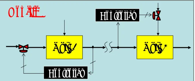
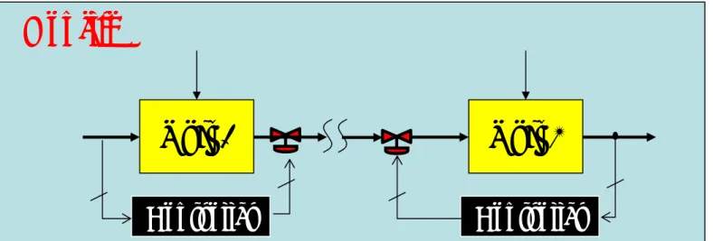
Control of Process-to-Process Exchangers
Control of Process-to-Process Exchangers
•
Bypass control
A. Controlling and
bypassing hot stream B. Controlling cold stream
and bypassing hot stream
C. Controlling and
bypassing cold stream D. Controlling hot stream
and bypassing cold stream.