Logix5000 Controller Design Considerations
Solid-state equipment has operational characteristics differing from those of electromechanical equipment. Safety
Guidelines for the Application, Installation and Maintenance of Solid State Controls (publication
SGI-1.1
available from
your local Rockwell Automation® sales office or online at
http://www.rockwellautomation.com/literature/
) describes some
important differences between solid-state equipment and hard-wired electromechanical devices. Because of this difference,
and also because of the wide variety of uses for solid-state equipment, all persons responsible for applying this equipment
must satisfy themselves that each intended application of this equipment is acceptable.
In no event will Rockwell Automation, Inc. be responsible or liable for indirect or consequential damages resulting from the
use or application of this equipment.
The examples and diagrams in this manual are included solely for illustrative purposes. Because of the many variables and
requirements associated with any particular installation, Rockwell Automation, Inc. cannot assume responsibility or
liability for actual use based on the examples and diagrams.
No patent liability is assumed by Rockwell Automation, Inc. with respect to use of information, circuits, equipment, or
software described in this manual.
Reproduction of the contents of this manual, in whole or in part, without written permission of Rockwell Automation,
Inc., is prohibited.
Throughout this manual, when necessary, we use notes to make you aware of safety considerations.
Allen-Bradley, Rockwell Software, Rockwell Automation, RSLinx, Logix5000, RSLogix 5000, RSNetWorx for ControlNet, RSNetWorx for DeviceNet, RSNetWorx for EtherNet/IP, ControlLogix, GuardLogix, CompactLogix, SoftLogix, FlexLogix, PowerFlex 700S, DriveLogix, FactoryTalk, FactoryTalk Administration Console, FactoryTalk Alarms and Events, FactoryTalk Live Data, FactoryTalk View, FactoryTalk View Studio, Kinetix 6000, RSView32, Synchlink, PLC-5, SLC, SLC 500, RSBizWare Batch, ControlFLASH, Ultra 3000, PanelView, PanelView Plus, and TechConnect are trademarks of Rockwell Automation, Inc.
Trademarks not belonging to Rockwell Automation are property of their respective companies.
WARNING:
Identifies information about practices or circumstances that can cause an explosion in a hazardous environment,
which may lead to personal injury or death, property damage, or economic loss.
ATTENTION:
Identifies information about practices or circumstances that can lead to personal injury or death, property
damage, or economic loss. Attentions help you identify a hazard, avoid a hazard, and recognize the consequence.
SHOCK HAZARD:
Labels may be on or inside the equipment, for example, a drive or motor, to alert people that dangerous
voltage may be present.
BURN HAZARD:
Labels may be on or inside the equipment, for example, a drive or motor, to alert people that surfaces may
reach dangerous temperatures.
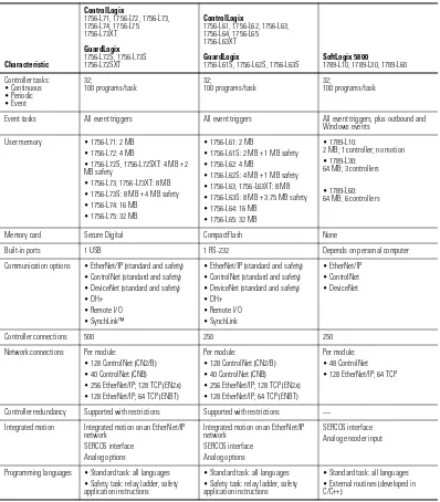
Table 1 - ControlLogix®, GuardLogix®, and SoftLogix™ Characteristics Characteristic ControlLogix 1756-L71,1756-L72,1756-L73, 1756-L74,1756-L75 1756-L73XT GuardLogix 1756-L72S,1756-L73S 1756-L72SXT ControlLogix 1756-L61,1756-L62,1756-L63, 1756-L64,1756-L65 1756-L63XT GuardLogix
1756-L61S,1756-L62S,1756-L63S SoftLogix58001789-L10,1789-L30,1789-L60 Controllertasks:
•Continuous •Periodic •Event
32;
100programs/task 32;100programs/task 32;100programs/task
Eventtasks Alleventtriggers Alleventtriggers Alleventtriggers,plusoutboundand Windowsevents Usermemory •1756-L71:2MB •1756-L72:4MB •1756-L72S,1756-L72SXT:4MB+2 MBsafety •1756-L73,1756-L73XT:8MB •1756-L73S:8MB+4MBsafety •1756-L74:16MB •1756-L75:32MB •1756-L61:2MB •1756-L61S:2MB+1MBsafety •1756-L62:4MB •1756-L62S:4MB+1MBsafety •1756-L63,1756-L63XT:8MB •1756-L63S:8MB+3.75MBsafety •1756-L64:16MB •1756-L65:32MB •1789-L10: 2MB;1controller;nomotion •1789-L30: 64MB;3controllers •1789-L60: 64MB;6controllers
Memorycard SecureDigital CompactFlash None
Built-inports 1USB 1RS-232 Dependsonpersonalcomputer
Communicationoptions •EtherNet/IP(standardandsafety) •ControlNet(standardandsafety) •DeviceNet(standardandsafety) •DH+ •RemoteI/O •SynchLink™ •EtherNet/IP(standardandsafety) •ControlNet(standardandsafety) •DeviceNet(standardandsafety) •DH+ •RemoteI/O •SynchLink •EtherNet/IP •ControlNet •DeviceNet
Controllerconnections 500 250 250
Networkconnections Permodule:
•128ControlNet(CN2/B) •40ControlNet(CNB) •256EtherNet/IP;128TCP(EN2x) •128EtherNet/IP;64TCP(ENBT)
Permodule:
•128ControlNet(CN2/B) •40ControlNet(CNB) •256EtherNet/IP;128TCP(EN2x) •128EtherNet/IP;64TCP(ENBT)
Permodule: •48ControlNet •128EtherNet/IP;64TCP
4 Rockwell Automation Publication 1756-RM094H-EN-P - November 2012
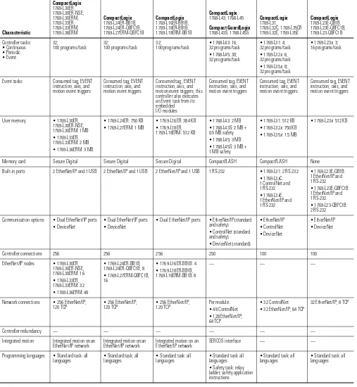
Table 2 - CompactLogix™ Characteristics
Characteristic CompactLogix 1769-L30ER, 1769-L30ER-NSE, 1769-L30ERM, 1769-L33ER, 1769-L33ERM, 1769-L36ERM CompactLogix 1769-L24ER-BB1B, 1769-L24ER-QBFC1B, 1769-L27ERM-QBFC1B CompactLogix 1769-L16ER-BB1B, 1769-L18ER-BB1B, 1769-L18ERM-BB1B CompactLogix 1768-L43,1768-L45 CompactGuardLogix 1768-L43S,1768-L45S CompactLogix 1769-L31, 1769-L32C,1769-L35CR 1769-L32E,1769-L35E CompactLogix 1769-L23E-QB1B, 1769-L23E-QBFC1B, 1769-L23-QBFC1B Controllertasks: •Continuous •Periodic •Event 32;
100programs/task 32;100programs/task 32;100programs/task •1768-L43:16;32programs/task •1768-L45:30; 32programs/task
•1769-L31:4; 32programs/task •1769-L32x:6; 32programs/task •1769-L35x:8; 32programs/task
•1769-L23x:3; 16programs/task Eventtasks Consumedtag,EVENT instruction,axis,and motioneventtriggers Consumedtag,EVENT instruction,axis,and motioneventtriggers Consumedtag,EVENT instruction,axis,and motioneventtriggers;this controlleralsoexecutes anEventtaskfromits embedded I/Omodules Consumedtag,EVENT instruction,axis,and motioneventtriggers Consumedtag,EVENT instruction,axis,and motioneventtriggers Consumedtag,EVENT instruction,axis,and motioneventtriggers Usermemory •1769-L30ER, 1769-L30ER-NSE, 1769-L30ERM:1MB •1769-L33ER, 1769-L33ERM:2MB •1769-L36ERM:3MB •1769-L24ER:750KB •1769-L27ERM:1MB •1769-L16ER:384KB •1769-L18ER, 1769-L18ERM:512KB •1768-L43:2MB •1768-L43S:2MB+ 0.5MBsafety •1768-L45:3MB •1768-L45S:3MB+ 1MBsafety •1769-L31:512KB •1769-L32x:750KB •1769-L35x:1.5MB
•1769-L23x:512KB
Memorycard SecureDigital SecureDigital SecureDigital CompactFLASH CompactFLASH None
Built-inports 2EtherNet/IPand1USB 2EtherNet/IPand1USB 2EtherNet/IPand1USB 1RS-232 •1769-L31:2RS-232 •1769-L3xC: 1ControlNetand 1RS-232 •1769-L3xE: 1EtherNet/IPand 1RS-232 •1769-L23E-QB1B: 1EtherNet/IPand 1RS-232 •1769-L23E-QBFC1B: 1EtherNet/IPand 1RS-232 •1769-L23-QBFC1B: 2RS-232 Communicationoptions •DualEtherNet/IPports •DeviceNet •DualEtherNet/IPports •DeviceNet •DualEtherNet/IPports •EtherNet/IP(standard andsafety) •ControlNet(standard andsafety) •DeviceNet(standard) •EtherNet/IP •ControlNet •DeviceNet •EtherNet/IP •DeviceNet
Controllerconnections 256 256 256 250 100 100
EtherNet/IPnodes •1769-L30ER, 1769-L30ER-NSE, 1769-L30ERM:16 •1769-L33ER, 1769-L33ERM:32 •1769-L36ERM:48 •1769-L24ER-BB1B, 1769-L24ER-QBFC1B,8 •1769-L27ERM-QBFC1B, 16 •1769-L16ER-BB1B:4 •1769-L18ER-BB1B, 1769-L18ERM-BB1B:8 — — — Networkconnections •256EtherNet/IP;
120TCP •256EtherNet/IP;120TCP •256EtherNet/IP;120TCP Permodule:•48ControlNet •128EtherNet/IP; 64TCP
•32ControlNet •32EtherNet/IP;64TCP
32EtherNet/IP;8TCP
Controllerredundancy — — — — — —
Integratedmotion Integratedmotiononan
EtherNet/IPnetwork IntegratedmotiononanEtherNet/IPnetwork IntegratedmotiononanEtherNet/IPnetwork SERCOSinterface — — Programminglanguages •Standardtask:all
languages •Standardtask:alllanguages •Standardtask:alllanguages •Standardtask:alllanguages •Safetytask:relay ladder,safetyapplication instructions
•Standardtask:all
This manual contains new and updated information. Changes throughout this
revision are marked by change bars, as shown to the right of this paragraph.
New and Updated
Information
The table contains the changes made to this revision.
For design guidelines regarding Logix5000 controllers in process control systems,
see the PlantPAx Process Automation System Reference Manual, publication
PROCES-RM001
.
There is
no
firmware available for the following controllers in the Studio 5000™
environment, version 21 and later.
Topic Page
Project documentation storage 13
Extended tag properties 55
Peer to peer control format 64
Stratix 5700 switches 81
Reduced memory use for each FactoryTalk Alarms and Events subscriber that receives alarms from the controller
93
Enhancements to alarm instructions 93
Digitally-signed firmware 109
Controller Platform Cat. Nos.
1768 CompactLogix • 1768-L43
• 1768-L43S
• 1768-L45
• 1768-L45S 1769 CompactLogix • 1769-L23E-QBF1
• 1769-L23E-QBFC1
• 1769-L23-QBFC1
• 1769-L31
• 1769-L32C
• 1769-L32E
• 1769-L35CR
• 1769-L35E
ControlLogix • 1756-L61
• 1756-L61S
• 1756-L62
• 1756-L62S
6 Rockwell Automation Publication 1756-RM094H-EN-P - November 2012
Preface
Additional Resources . . . 11
Websites . . . 11
Chapter 1
Logix5000 Controller Resources
Estimate Memory Use . . . 15
RSLinx Software Use of Logix5000 Controller Memory . . . 16
Compare PLC/SLC MEMORY . . . 16
Controller Connections . . . 16
Determine Total Connection Requirements. . . 18
CIP Sync . . . 19
Controller Mode . . . 20
Chapter 2
Divide Logic into Tasks, Programs,
Routines, and Add-On Instructions
Decide When to Use Tasks, Programs, and Routines . . . 22
Specify Task Priorities . . . 22
Manage User Tasks. . . 24
Considerations that Affect Task Execution . . . 25
Configure a Continuous Task . . . 27
Configure a Periodic Task . . . 27
Configure an Event Task. . . 28
Guidelines to Configure an Event Task. . . 28
Additional Considerations for Periodic and Event Tasks. . . 29
Select a System Overhead Percentage. . . 30
Manage the System Overhead Timeslice Percentage . . . 31
Develop Application Code in Routines . . . 32
Comparison of Programming Languages . . . 33
Guidelines to Pass Parameters to/from Subroutines . . . 33
Guidelines for Add-On Instructions . . . 34
Comparison of Subroutines and Add-On Instructions . . . 35
Guidelines for Code Reuse . . . 35
Comparison of Partial Import/Export and Add-On Instructions . 36
Programming Methods . . . 36
8 Rockwell Automation Publication 1756-RM094H-EN-P - November 2012
Chapter 3
Address Data
Guidelines for Data Types . . . 44
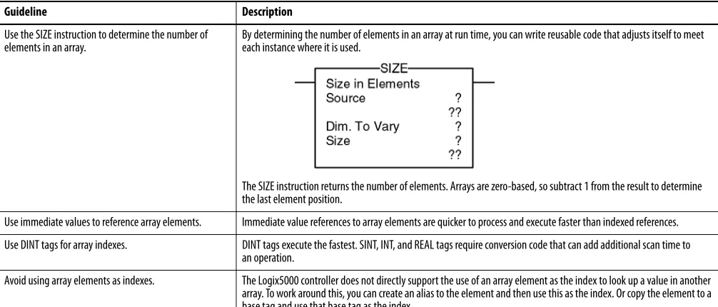
Arrays . . . 45
Guidelines for Arrays . . . 46
Indirect Addresses of Arrays. . . 46
Guidelines for Array Indexes . . . 48
Guidelines for User-defined Structures . . . 48
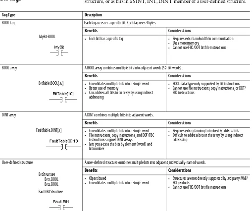
Select a Data Type for Bit Tags . . . 49
Serial Bit Addresses. . . 50
Guidelines for String Data Types . . . 51
PLC-5/SLC 500 Access of Strings . . . 51
Configure Tags . . . 52
Guidelines for Base Tags . . . 52
Create Alias Tags. . . 53
Guidelines for Data Scope. . . 54
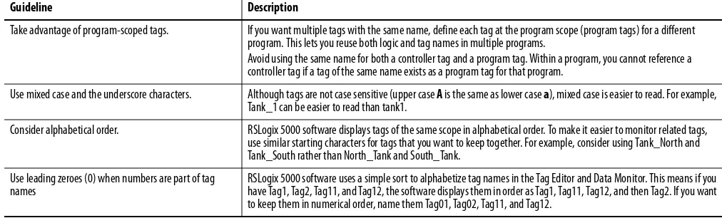
Guidelines for Tag Names . . . 54
Guidelines for Extended Tag Properties . . . 55
Tag Descriptions . . . 56
Protect Data Access Control at Tag Level . . . 56
Chapter 4
Produced and Consumed Data
Guidelines for Produced and Consumed Tags . . . 57
Guidelines to Specify an RPI Rate for Produced and Consumed Tags . 59
Guidelines to Manage Connections for Produced and Consumed Tags 59
Configure an Event Task Based on a Consumed Tag . . . 59
Compare Messages and Produced/Consumed Tags . . . 60
Chapter 5
Communicate with I/O
Buffer I/O Data. . . 61
Guidelines to Specify an RPI Rate for I/O Modules . . . 62
Communication Formats for I/O Modules . . . 63
Electronic Keying. . . 65
Guidelines to Manage I/O Connections. . . 66
Control 1771 I/O Modules . . . 67
Communicate with HART Devices. . . 68
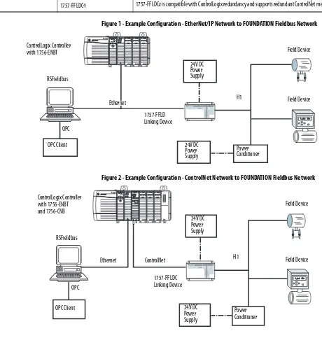
Communicate with FOUNDATION Fieldbus Devices . . . 69
Create Tags for I/O Data . . . 71
Controller Ownership . . . 72
Runtime/Online Addition of Modules. . . 73
Chapter 6
Determine the Appropriate Network
EtherNet/IP Network Topology . . . 78
Guidelines for EtherNet/IP Networks . . . 79
Guidelines for Switches in EtherNet/IP Systems . . . 80
Determine Whether Your System Operates Properly . . . 80
Stratix Industrial Switches . . . 81
ControlNet Network Topology . . . 81
Guidelines for ControlNet Networks . . . 82
Guidelines for Unscheduled ControlNet Networks . . . 83
Compare Scheduled and Unscheduled ControlNet Communication . 84
DeviceNet Network Topology . . . 84
Guidelines for DeviceNet Networks . . . 85
Chapter 7
Communicate with Other Devices
Cache Messages . . . 88
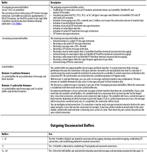
Message Buffers . . . 88
Outgoing Unconnected Buffers. . . 89
Guidelines for Messages. . . 90
Guidelines to Manage Message Connections. . . 90
Guidelines for Block-transfer Messages . . . 91
Map Tags. . . 91
Chapter 8
FactoryTalk Alarms and Events
System
Guidelines for Logix-based Alarm Instructions. . . 93
Changes in Logic . . . 95
Configure Logix-based Alarm Instructions . . . 96
Multiple Language Versions of Alarm Messages . . . 97
Alarm Process. . . 98
Alarm Log . . . 99
Programmatically Access Alarm Information . . . 99
Shelve, Suppress, or Disable Alarms . . . 100
Chapter 9
Optimize an Application for Use with
HMI
HMI Implementation Options . . . 101
10 Rockwell Automation Publication 1756-RM094H-EN-P - November 2012
Chapter 11
Manage Firmware
Guidelines to Manage Controller Firmware . . . 109
Compare Firmware Options . . . 110
Guidelines for the Firmware Supervisor . . . 111
Access Firmware . . . 112
Additional Resources
These documents contain additional information about Logix5000 controllers.
You can view or download publications at
http:/www.rockwellautomation.com/literature/
. To order paper copies of
technical documentation, contact your local Allen-Bradley distributor or
Rockwell Automation sales representative.
Websites
Resource Description
• EtherNet/IP Modules in Logix5000 Control Systems User Manual, ENET-UM001
• ControlNet Modules in Logix5000 Control Systems User Manual, CNET-UM001
• DeviceNet Modules in Logix5000 Control Systems User Manual, DNET-UM004
Networks
• Logix5000 Common Procedures Programming Manual, 1756-PM001
• Logix5000 Controllers General Instructions Reference Manual, 1756-RM003
• Logix5000 Controllers Process Control and Drives Instructions Reference Manual, 1756-RM006
• Phase Manager User Manual, LOGIX-UM001
• Logix5000 Controllers Motion Instructions Reference Manual, MOTION-RM002
• Logix5000 Controllers Import/Export Reference Manual, 1756-RM084
Logix5000 Controllers
• ControlLogix System User Manual, 1756-UM001
• Motion Configuration and Startup User Manual, MOTION-UM001
• Motion Coordinate System User Manual, MOTION-UM002
ControlLogix Controllers
• CompactLogix 5370 Controllers User Manual, 1769-UM021
• 1768 CompactLogix System User Manual, 1768-UM001
• 1769 CompactLogix System User Manual, 1769-UM011
• 1769 Packaged CompactLogix Controllers Quick Start and User Manual, IASIMP-QS010
CompactLogix Controllers
• SoftLogix System User Manual, 1789-UM002 SoftLogix Controllers
Resource Description
http://www.ab.com/logix/ Logix Product Information
http://www.ab.com/networks/ Network Product Information
http://www.rockwellautomation.com/support/
In the left pane under Downloads, select Software Updates.
Software Updates
(product serial number required)
http://www.rockwellautomation.com/support
In the left pane under Downloads, select Firmware Updates.
Firmware Updates
(product serial number required)
12 Rockwell Automation Publication 1756-RM094H-EN-P - November 2012
Logix5000 Controller Resources
The Logix CPU executes application code and messages. The backplane CPU
transfers I/O memory and other module data on the backplane. This CPU
operates independently from the Logix CPU, so it sends and receives I/O
information asynchronous to program execution.
Logic and Data Memory
Logix CPU
Backplane CPU I/O Memory
Program source code
Tag data
RSLinx tag group lists
I/O data
I/O force tables
Message buffers
Produced/consumed tags
1756-L7x ControlLogix controllers - Memory is separated into isolated sections.
Project Documentation Memory
Comment descriptions
Alarm log
Extended tag properties
Logic and Data Memory
Logix CPU
Backplane CPU I/O Memory
Program source code
Tag data
RSLinx tag group lists
I/O data
I/O force tables
Message buffers
Produced/consumed tags
14 Rockwell Automation Publication 1756-RM094H-EN-P - November 2012
The Logix CPU executes application code and messages.
These controllers have a single CPU that performs all operations. Isolated tasks
perform I/O and communication and interact with networks. These tasks
simulate the backplane CPU.
I/O Memory
Program source code
Tag data
RSLinx tag group lists
I/O data
I/O force tables
Message buffers
Produced/consumed tags
CompactLogix 5370 controllers - Memory is separated into isolated segments.
Logix CPU Logic and Data Memory
Comment descriptions
Alarm log
Extended tag properties
Project Documentation Memory
Controller I/O Task Priority Communication Task Priority
CompactLogix 5370 6 12
Logic, Data, and I/O Memory
Logix CPU
Program source code
Tag data
RSLinx tag group lists
I/O data
I/O force tables
Message buffers
Produced/consumed tags
I/O task Comms task 1769 CompactLogix controllers - Memory is in one, contiguous section.
Controller I/O Task Priority Communication Task Priority
The SoftLogix controller has a single CPU that works in conjunction with the
Windows operating system to perform all operations. Rather than using
controller priority levels for I/O and communication tasks, the SoftLogix
controller uses Windows priority levels for these tasks.
For all controllers, memory is used at run time for the following:
•
Message processing
•
RSLinx® data handling to store tag groups
•
Online edits to store edit rungs
•
Graphical trends to buffer data
Estimate Memory Use
These equations provide an estimate of the memory needed for a controller.
Controller tasks
_____ * 4,000
=
_____ bytes (minimum 1 needed)
Digital I/O points
_____ *
400
=
_____ bytes
Logic, Data, and I/O Memory
Logix CPU
Program source code
Tag data
RSLinx tag group lists
I/O data
I/O force tables
Message buffers
Produced/consumed tags
SoftLogix controllers - Memory is in one, contiguous section.
Windows operating
system Project Documentation Memory
Comment descriptions
Alarm log
Extended tag properties
Controller I/O Task Priority Communication Task Priority
SoftLogix Windows priority 16 (Idle)
Windows priority 16 (Idle)
16 Rockwell Automation Publication 1756-RM094H-EN-P - November 2012
2Count all the communication modules in the system, not just those in the local chassis. This includes device connection modules, adapter modules, and ports on PanelView™ terminals.
RSLinx Software Use of Logix5000 Controller Memory
The amount of memory that RSLinx software needs depends on the type of data
RSLinx software reads. These equations provide a memory estimate.
RSLinx overhead
(per connection)
_____ * 1345 = _____ bytes (4 connections by default)
Individual tags
_____ * 45
= _____ bytes
Arrays / structures
_____ * 7
= _____ bytes
Total
= _____ bytes
Consolidating tags into an array or a structure reduces the communication
overhead and the number of connections needed to obtain the data.
Compare PLC/SLC MEMORY
The Logix5000 controllers use compiled instructions to provide faster execution
times than PLC or SLC processors. The compiled instructions use more memory
when compared to the instructions in PLC and SLC processors.
If you have a PLC/SLC program, you can estimate the number of bytes it will
take in a Logix5000 controller by the following equation:
number PLC/SLC words
∗
18 =
number of Logix5000 bytes
Controller Connections
A Logix5000 controller uses a connection to establish a communication link
between two devices. Connections can be made to the following:
•
Controller to local I/O modules or local communication modules
•
Controller to remote I/O or remote communication modules
•
Controller to remote I/O (rack optimized) modules
For more information on connections for I/O, see
Communicate with I/O
on page 61
.
•
Produced and consumed tags
For more information, see
Produced and Consumed Data on page 57
.
•
Messages
For more information, see
Communicate with I/O on page 61
.
•
Access to RSLogix™ 5000 software
•
RSLinx software access for HMI or other software applications
The controllers have different communication limits.
The limit of connections may ultimately reside in the communication module
you use for the connection. If a message path routes through a communication
module, the connection related to the message also counts toward the connection
limit of that communication module.
Communication Attribute 1756-L7x ControlLogix 1756-L6x ControlLogix and SoftLogix
1769 CompactLogix CompactLogix 5370 1768 CompactLogix
Connections 500 250 100 256 250
Cached messages(1) 32 for messages and block-transfers combined Unconnected receive buffers 3
Unconnected transmit buffers Default 20 (can be increased to 40)
Default 10 (can be increased to 40)
(1) See Communicate with Other Devices on page 87 for more information about messages and buffers.
Controller Communication Device Supported Connections
ControlLogix 1756-CN2R, 1756-CN2RXT
1756-CN2/B
100 CIP connections
(any combination of scheduled and message connections)
128 CIP connections 1756-CNB,1756 -CNBR 64 CIP connections
depending on RPI, recommend using only 48 connections (any combination of scheduled and message connections) EN2F, EN2T, EN2TR,
1756-EN2TXT, 1756-EN3TR
256 CIP connections 128 TCP/IP connections 1756-ENBT
1756-EWEB
128 CIP connections 64 TCP/IP connections 1768 CompactLogix 1768-ENBT
1768-EWEB
64 CIP connections 32 TCP/IP connections 1769 CompactLogix 1769-L32C, 1769-L35CR 32 CIP connections
depending on RPI, as many as 22 connections can be scheduled
The remaining connections (or all 32, if you have no scheduled connections) can be used for message connections
1769-L32E, 1769-L35E 32 CIP connections 64 TCP/IP connections 1769-L23Ex 32 CIP connections
12 TCP/IP connections
18 Rockwell Automation Publication 1756-RM094H-EN-P - November 2012
Determine Total Connection
Requirements
The total connections for a Logix5000 controller include both local and remote
connections. Tallying local connections is not an issue for CompactLogix
controllers because they support the maximum number of modules allowed in
their systems.
When designing your CompactLogix 5370 controllers, you must consider
these resources:
•
EtherNet/IP network nodes
•
Controller connections
For more information, see the CompactLogix 5370 Controllers User Manual,
publication
1769-UM021
.
The ControlLogix and SoftLogix controllers support more communication
modules than the other controllers, so you must tally local connections to make
sure you stay within the connection limit.
Use this table to tally
local
connections.
Connection Type Device Quantity
x
Connections
per Module =
Total Connections
Local I/O module (always a direct connection) x 1 =
SERCOS Motion module x 3 =
ControlNet communication module x 0 =
EtherNet/IP communication module x 0 =
DeviceNet communication module x 2 =
DH+/Remote I/O communication module x 1 =
DH-485 communication module x 1 =
RSLogix 5000 software access to controller x 1 =
Total
The communication modules you select determine how many remote
connections are available. Use this table to tally
remote
connections.
CIP Sync
CIP Sync is a time synchronization implementation that incorporates
IEEE-1588 standards on the EtherNet/IP protocol. This provides the control
system access to synchronization information and transport and routing of a
system clock on standard CIP networks.
CIP Sync offers the following features:
•
Precision Time Protocol (PTP)
•
Nanosecond resolution +/- 100 nanosecond synchronization (hardware
assist clock)
•
Master clock reference
•
No longer need application code or software to synchronize clocks
Connection Type Device Quantity
x
Connections
per Module =
Total Connections
Remote ControlNet communication module Configured as a direct (none) connection Configured as a rack-optimized connection
x 0 or
1
=
Remote EtherNet/IP communication module Configured as a direct (none) connection Configured as a rack-optimized connection
x 0 or
1
=
Remote device over a DeviceNet network
(accounted for in rack-optimized connection for local DeviceNet module)
x 0 =
Safety device on a DeviceNet or EtherNet/IP network x 2 =
Other remote communication adapter x 1 =
Distributed I/O module (individually configured for a direct connection) x 1 = Produced tag and first consumer
Each additional consumer
x 2 1
=
Consumed tag x 1 =
Connected message (CIP Data Table Read/Write and DH+) x 1 =
Block-transfer message x 1 =
20 Rockwell Automation Publication 1756-RM094H-EN-P - November 2012
The controller or networked device that wins system clock arbitration will be the
Grand Master clock. The wall clock time can only be set from the system Grand
Master device. If you adjust a controller clock, the controller could reject that
time if it is not or does not become the Grand Master clock.
You can configure the system clock via RSLogix 5000 software, version 18 and
later, and programmatically via GSV/SSV instructions. Use a GSV/SSV
instruction with the Time Sync object to do the following:
•
Enable or disable CIP sync
•
Get or set the time
•
Set priority to override other masters
•
Get synchronization status
•
Get current PTP master status and state information
Controller Mode
The controller mode switch provides a mechanical means to enhance controller
and control system security. You must physically move the controller’s mode
switch to change its operating mode from RUN to REM or to PROG.
Remote lets you change the operational mode to REM RUN or REM PROG via
RSLogix 5000 software.
For more information on controller mode switches, see the ControlLogix System
User Manual, publication
1756-UM001
.
Divide Logic into Tasks, Programs, Routines, and
Add-On Instructions
The controller operating system is a preemptive multitasking system that is
IEC 61131-3 compliant.
A task provides scheduling and priority information for a set of one or more
programs. You can configure tasks as either continuous, periodic, or event.
A task contains programs, each with its own routines and program-scoped tags.
Once a task is triggered (activated), all the programs assigned to the task execute
in the order in which they are listed in the Controller Organizer.
Programs are useful for projects developed by multiple programmers. During
development, the code in one program that makes use of program-scoped tags
can be duplicated in a second program to minimize the possibility of tag
names colliding.
With firmware revision 15, tasks can contain programs and equipment phases.
Routines contain the executable code. Each program has a main routine that is
the first routine to execute within a program. Use logic, such as the Jump to
Subroutine ( JSR) instruction, to call other routines. You can also specify an
optional program fault routine.
See
Develop Application Code in Routines on page 32
for information on
selecting programming languages and how the controller prescans and
postscans logic.
An Add-On Instruction is a user-created instruction that encapsulates logic.
Add-On Instructions help divide a controller project into smaller, more
manageable pieces.
Tasks to configure controller execution
Programs to group data and logic
Routines to encapsulate executable code written in a single programming language
22 Rockwell Automation Publication 1756-RM094H-EN-P - November 2012
Decide When to Use Tasks,
Programs, and Routines
Use these considerations to determine when to use a task, program, or routine.
For more information about equipment phases, see
Develop Equipment Phases
on page 107
.
Specify Task Priorities
Each task in the controller has a priority level. A higher priority task (such as 1)
interrupts any lower priority task (such as 15). The continuous task has the
lowest priority and is always interrupted by a periodic or event task.
Comparison Task Program and Equipment Phase Routine Add-On Instruction
Quantity available Varies by controller (4, 6, 8, or 32) 32 program and equipment phases (combined) per task
(100 for ControlLogix and SoftLogix controllers)
Unlimited number of routines per program
Unlimited number of Add-On Instructions in a project
Function Determines how and when code will be executed
Organizes groups of routines that need to share a common data area and function.
Contains executable code (relay ladder, function block diagram, sequential function chart, or structured text)
Contains executable code (relay ladder, function block diagram, or structured text)
Use • Most code should reside in a continuous task
• Use a periodic task for slower processes or when time-based operation is critical
• Use an event task for operations that require synchronization to a specific event
• Put major equipment pieces or plant cells into isolated programs
• Use programs to isolate different programmers or create reusable code
• Configurable execution order within a task
• Isolate individual batch phases or discrete machine operations
• Isolate machine or cell functions in a routine
• Use the appropriate language for the process
• Modularize code into subroutines that can be called multiple times
• Standardize modules of code
• Very specific or focused operations
• Extensions to the base instruction set
• Encapsulate an instruction from one language for use in another language
• Instance based monitoring of logic and data
Considerations • A high number of tasks can be difficult to debug
• May need to disable output processing on some tasks to improve performance
• Tasks can be inhibited to prevent execution
• Do not configure multiple tasks at the same priority
• Data spanning multiple programs must go into controller-scoped area
• Listed in the Controller Organizer in the order of execution
• Subroutines with multiple calls can be difficult to debug
• Data can be referenced from program-scoped and controller-scoped areas
• Calling a large number of routines impacts scan time
• Listed in the Controller Organizer as Main, Fault, and then alphabetically
• If you have a lot of parameters or specialized options, consider multiple Add-On Instructions
• Calling a large number of Add-On Instructions impacts scan time
• Must use cross-reference or find to locate calls to an Add-On Instruction
• Can edit offline only
• Supports only some data types.
• Changes to data values must be made for each instance
This Logix5000 controller Supports this many user tasks And has this many priority levels
ControlLogix 32 15
CompactLogix 5370 32 15
1768-L43, 1769-L45 CompactLogix 16 15
1769-L35CR, 1769-L35E CompactLogix 8 15
1769-L32C,1769-L32E CompactLogix 6 15
1769-L31 CompactLogix 4 15
1769-L23E-QB1B, 1769-L23E-QBFC1B, 1769-L23-QBFC1B CompactLogix
3 15
The Logix5000 controller has these types of tasks.;
If a periodic or event task is executing when another is triggered and both tasks
are at the same priority level, the tasks timeslice executes in 1 ms increments until
one of the tasks completes execution.
Priority User Task Description
Highest
Lowest
N/A CPU overhead - serial port and general CPU operations N/A Motion planner - executed at coarse update rate N/A Safety task - safety logic
N/A Redundancy task - communication in redundant systems N/A Trend data collection - high-speed collection of trend data values Priority 1 Event/Periodic User defined
Priority 2 Event/Periodic User defined Priority 3 Event/Periodic User defined Priority 4 Event/Periodic User defined Priority 5 Event/Periodic User defined Priority 6 Event/Periodic User defined
1769 CompactLogix controllers process I/O as a periodic task based on the chassis RPI setting Priority 7 Event/Periodic User defined
Priority 8 Event/Periodic User defined Priority 9 Event/Periodic User defined Priority 10 Event/Periodic User defined Priority 11 Event/Periodic User defined Priority 12 Event/Periodic User defined
CompactLogix communication and scheduled connection maintenance Priority 13 Event/Periodic User defined
Priority 14 Event/Periodic User defined Priority 15 Event/Periodic User defined
24 Rockwell Automation Publication 1756-RM094H-EN-P - November 2012
Manage User Tasks
You can configure these user tasks.
The user tasks you create appear in the Tasks folder of the controller. These
pre-defined system tasks do not appear in the Tasks folder and they do not count
toward the task limit of the controller:
•
Motion planner
•
I/O processing
•
System overhead
•
Output processing
If you want logic to execute Then use a Description
All of the time Continuous task The continuous task runs in the background. Any CPU time not allocated to other operations or tasks is used to execute the continuous task.
• The continuous task runs all the time. When the continuous task completes a full scan, it restarts immediately.
• A project does not require a continuous task. If used, there can be only one continuous task.
• At a constant period (such as every 100 ms)
• Multiple times within the scan of your other logic
Periodic task A periodic task performs a function at a specific time interval. Whenever the time for the periodic task expires, the periodic task:
• Interrupts any lower priority tasks.
• Executes one time.
• Returns control to where the previous task left off.
Immediately when an event occurs Event task An event task performs a function only when a specific event (trigger) occurs. Whenever the trigger for the event task occurs, the event task:
• Interrupts any lower priority tasks.
• Executes one time.
• Returns control to where the previous task left off.
Considerations that Affect Task Execution
Consideration Description
Motion planner The motion planner interrupts all other tasks, regardless of their priority.
• The number of axes and coarse update period for the motion group affect how long and how often the motion planner executes.
• If the motion planner is executing when a task is triggered, the task waits until the motion planner is done.
• If the coarse update period occurs while a task is executing, the task pauses to let the motion planner execute. I/O processing CompactLogix and SoftLogix controllers use a dedicated periodic task to process I/O data. This I/O task:
• CompactLogix controllers, operates at priority 6.
SoftLogix controllers, operates at Windows priority 16 (Idle).
• Higher-priority tasks take precedence over the I/O task and can impact processing.
• Executes at the fastest RPI you have scheduled for the system.
• Executes for as long as it takes to scan the configured I/O modules. System overhead
See also Select a System Overhead Percentage on page 30.
System overhead is the time that the controller spends on message communication and background tasks.
• Message communication is any communication that you do not configure through the I/O configuration folder of the project, such as MSG instructions.
• Message communication occurs only when a periodic or event task is not running. If you use multiple tasks, make sure that their scan times and execution intervals leave enough time for message communication.
• System overhead interrupts only the continuous task.
• The system overhead timeslice specifies the percentage of time (excluding the time for periodic or event tasks) that the controller devotes to message communication.
• The controller performs message communication for up to 1 ms at a time and then resumes the continuous task.
• Adjust the update rates of the tasks as needed to get the best trade-off between executing your logic and servicing message communication.
Output processing At the end of a task, the controller performs output processing for the output modules in your system. This processing depends on the number of output connections configured in the I/O tree.
Too many tasks If you have too many tasks, then the following may occur:
• Continuous task may take too long to complete .
• Other tasks may experience overlaps. If a task is interrupted too frequently or too long, it may not complete its execution before it is triggered again.
• Controller communication might be slower.
26 Rockwell Automation Publication 1756-RM094H-EN-P - November 2012
This example depicts the execution of a project with these tasks.
Task Priority Period Execution Time Duration
Motion planner N/A 8 ms (course update rate) 1 ms 1 ms
Event task 1 1 N/A 1 ms 1
…
2 msPeriodic task 1 2 12 ms 2 ms 2
…
4 msI/O task—N/A to ControlLogix and SoftLogix controllers 7 5 ms (fastest RPI) 1 ms 1
…
5 msSystem overhead N/A Timeslice = 20% 1 ms 1
…
6 msContinuous task N/A N/A 20 ms 48 ms
Legend: Task executes. Task is interrupted (suspended).
Motion Planner
Event Task 1
Periodic Task 1
I/O Task
System Overhead
Continuous Task
5 10 15 20 25 30 35 40 45 50
Description
Initially, the controller executes the motion planner and the I/O task (if one exists). After executing the continuous task for 4 ms, the controller triggers the system overhead. The period for periodic task 1 expires (12 ms), so the task interrupts the continuous task. After executing the continuous task again for 4 ms, the controller triggers the system overhead. The triggers occur for event task 1.
Event task 1 waits until the motion planner is done. Lower priority tasks experience longer delays. The continuous task automatically restarts.
1 2 3 4 5 6
1 2 3 4
5
Configure a Continuous Task
The continuous task is created automatically when you open an RSLogix 5000
software project. A continuous task is similar to how logic executes on PLC-5®
and SLC™ 500 processors. A Logix5000 controller supports one continuous task,
but a continuous task is not required. You can configure whether the task updates
output modules at the end of the continuous task. You can change the continuous
task to either a periodic or event task.
The CPU timeslices between the continuous task and system overhead. Each
task switch between user task and system overhead takes additional CPU time to
load and restore task information.
RSLogix 5000 software, version 16 and later, forces at least 1 ms of execution
time for the continuous task, regardless of the system overhead timeslice. This
more efficiently uses system resources because allowing shorter execution times of
the continuous task means switching tasks more frequently.
Configure a Periodic Task
A periodic task executes automatically based on a preconfigured interval. This
task is similar to selectable timed interrupts in PLC-5 and SLC 500 processors.
You can configure whether the task updates output modules at the end of the
periodic task. After the task executes, it does not execute again until the
configured time interval has elapsed.
If your application has a lot of communication, such as RSLinx communication,
use a periodic task rather than a continuous task.
System Overhead Timeslice %
Communication Execution (msec)
Continuous Task Execution (msec)
10 1 9
20 1 4
33 1 2
50 1 1
66 2 1
80 4 1
28 Rockwell Automation Publication 1756-RM094H-EN-P - November 2012
Configure an Event Task
An event task executes automatically based on a trigger event occurring or if a
trigger event does not occur in a specific time interval. You configure whether the
task updates output modules at the end of the task. After the task executes, it
does not execute again until the event occurs again. Each event task requires a
specific trigger.
For more information on event tasks, see:
•
Logix5000 Controllers Common Procedures Programming Manual,
publication
1756-PM001
•
Using Event Tasks with Logix5000 Controllers
publication
LOGIX-WP003
Guidelines to Configure an Event Task
Trigger Description
Module Input Data State Change With Logix5000 controllers, a remote input module (digital or analog) triggers an event task based on the change of state (COS) configuration for the module. Enable COS for only one point on the module. If you enable COS for multiple points, a task overlap of the event task may occur.
• The ControlLogix sequence of events modules (1756-IB16ISOE, 1756-IH16ISOE) use the Enable CST Capture feature instead of COS.
• The embedded input points on the 1769-L16ER-BB1B, 1769-L18ER-BB1B, and 1769-L18ERM-BB1B modules can be configured to trigger an event task when a COS occurs.
Consumed Tag Only one consumed tag can trigger a specific event task. Use an IOT instruction in the producing controller to signal the production of new data.
Axis Registration 1 or 2 A registration input triggers the event task. Axis Watch A watch position triggers the event task.
Motion Group Execution The coarse update period for the motion group triggers the execution of both the motion planner and the event task. Because the motion planner interrupts all other tasks, it executes first.
EVENT Instruction Multiple EVENT instructions can trigger the same task.
Guideline Description
Place the I/O module being used to trigger an event in the same chassis as the controller.
Placing the I/O module in a remote chassis adds additional network communication and processing to the response time.
Limit events on digital inputs to a single input bit on a module.
All inputs on a module trigger a single event, so using multiple bits increases the chance of a task overlap. Configure the module to detect change-of-state on the trigger input and turn off the other bits.
Set the priority of the event task as the highest priority on the controller.
If the priority of the event task is lower than a periodic task, the event task will have to wait for the periodic task to complete execution.
Additional Considerations for Periodic and Event Tasks
Consideration Description
Amount of code in the event task Each logic element (for example, rung, instruction, or structured text construct) adds to scan time.
Task priority If the event task is not the highest priority task, a higher priority task may delay or interrupt the execution of the event task.
CPS and UID instructions If one of these instructions are active, the event task cannot interrupt the currently executing task. (The task with the CPS or UID.)
Communication interrupts Incoming character processing through the serial port interupts a task, regardless of the priority of the task. Motion planner The motion planner takes precedence over event or periodic tasks
Trends Trend data collection takes precedence over event or periodic tasks.
30 Rockwell Automation Publication 1756-RM094H-EN-P - November 2012
Select a System Overhead
Percentage
The system overhead timeslice specifies the percentage of continuous task
execution time that is devoted to communication and background redundancy
functions. System overhead functions include the following:
•
Communicating with programming and HMI devices (such as
RSLogix 5000 software)
•
Responding to messages
•
Sending messages
•
Serial port message and instruction processing
•
Alarm instruction processing
•
Redundancy qualification
The controller performs system overhead functions for up to 1 ms at a time. If the
controller completes the overhead functions in less than 1 ms, it resumes the
continuous task. The following chart compares a continuous and periodic task.
The Logix5000 CPU timeslices between the continuous task and system
overhead. Each task switch between user task and system overhead takes
additional CPU time to load and restore task information. You can calculate the
continuous task interval as:
ContinuousTime=(100/SystemOverheadTimeSlice%) - 1
Continuous Task Restarts
Periodic Task Restarts Continuous Task
10% CPU Overhead
Continuous Task 25% CPU Overhead
Periodic Task CPU Overhead
Example Description
Continuous task 10% CPU overhead
In the top example, the system overhead timeslice is set to 10%. Given 40 ms of code to execute, the continuous task completes the execution in 44 ms. During a 60 ms timespan, the controller is able to spend 5 ms on
communication processing. Continuous task
25% CPU overhead
By increasing the system overhead timeslice to 25%, the controller completes the continuous task scan in 57 ms and spends 15 ms of a 60 ms timespan on communication processing.
Manage the System
Overhead Timeslice
Percentage
As the system overhead timeslice percentage increases, time allocated to executing
the continuous task decreases. If there is no communication for the controller
to manage, the controller uses the communication time to execute the
continuous task.
Individual applications may differ, but the overall impact on communication and
scan time remains the same. The above data is based on a ControlLogix5555
controller running a continuous task with 5000 tags (no arrays or
user-defined structures).
Consideration Description
Continuous task always has at least 1 ms execution time RSLogix 5000 software, version 16 and later, forces the continuous task to have at least 1 ms of execution time, regardless of the setting for the system overhead timeslice. This results in more efficient controller use because excessive swapping between tasks uses valuable CPU resources.
Impact on communication and scan time Increasing the system overhead timeslice percentage decreases execution time for the continuous task while it increases communication performance.
Increasing the system overhead timeslice percentage also increases the amount of time it takes to execute a continuous task - increasing overall scan time.
Unused portion of system overhead timeslice With RSLogix 5000 software, version 16, you can configure any unused portion of the system overhead timeslice to:
• Run the continuous task, which results in faster execution of application code and increases the variability of the program scan.
• Process communication, which results in more predictable and deterministic scan time for the continuous task. (This is for development and testing of an application to simulate communication.)
Program Scan Time Tags Per Second
System Timeslice %
Ta
gs per
Se
cond
Pr
ogram Sc
an Time in Mil
lisecon
32 Rockwell Automation Publication 1756-RM094H-EN-P - November 2012
Develop Application Code in
Routines
Each routine contains logic in one programming language. Choose a
programming language based on the application.
In general, if a section of your code represents Then use this language
Continuous or parallel execution of multiple operations (not sequenced) Relay ladder logic (LD) Boolean or bit-based operations
Complex logical operations
Message and communication processing Machine interlocking
Operations that service or maintenance personnel may have to interpret to troubleshoot the machine or process. Servo motion control
Continuous process and drive control Function block diagram (FBD) Loop control
Calculations in circuit flow
High-level management of multiple operations Sequential function chart (SFC) Repetitive sequences of operations
Batch process
Motion control sequencing (via sequential function chart with embedded structure text) State machine operations
Complex mathematical operations Structured text (ST)
Comparison of Programming Languages
Guidelines to Pass Parameters to/from Subroutines
Follow these parameter guidelines for subroutines.
Comparison Relay Ladder Logic Function Block Diagram Sequential Function Chart Structured Text
Instruction categories • Boolean
• General and trig math
• Timers and counters
• Array management
• Diagnostic
• Serial port and messaging
• ASCII manipulation
• Motion control
• General and trig math
• Timers and counters
• Bitwise logical
• Advanced process
• Advanced drive
• Step/action with embedded structured text
• Transition with structure text comparisons
• Simultaneous and selection branches
• Stop element
• General and trig math
• Timers and counters
• Bitwise logical
• Array management
• Diagnostic
• ASCII manipulation
• Specialty CPU control
• Motion control
• Advanced process
• Advanced drive Editor style • Graphical rungs
• Unlimited rungs
• Graphical, free-form drawing
• Unlimited sheets
• Graphical, free-form drawing
• Unlimited grid space
• Textual
• Unlimited lines Monitoring • Rung animation
• Data value animation
• Force status
• Output and input pin data value animation
• Active steps animation
• Auto display scroll
• Branch/transition force status
• Tag watch pane
• Context coloring
Comments • Tag
• Rung
• Tag
• Text box
• Tag
• Text box
• Embedded structured text comments stored in CPU
• Multi-line
• End if line
• Comments stored in CPU
Guideline Description
Input and Return parameters depend on the subroutine logic.
If the subroutine needs to know the previous state of any Return parameters (the values are used elsewhere in the project), these values should also be Input parameters:
• If the subroutine contains latch/unlatch logic (holding circuits), intended outputs of the subroutine should be passed into and returned from the subroutine.
• If the subroutine does not contain latch/unlatch logic, intended outputs of the subroutine only need to be returned from the subroutine.
Pass complete timers in and out of subroutines. If a subroutine needs a timer, pass the complete timer tag to the subroutine as an input and return the complete timer tag as an output. Store the timer in a buffer tag outside of the subroutine.
Create a user-defined tag to pass large numbers Input and Output parameters
Create and pass a UDT if you have several Input and Output parameters to save on execution time. The more parameters you pass, the fewer nested JSRs you can perform.
34 Rockwell Automation Publication 1756-RM094H-EN-P - November 2012
Guidelines for Add-On Instructions
An Add-On Instruction is a user-created instruction that encapsulates code
and local data.
Guideline Description
Create Add-On Instructions in relay ladder, function block diagram, or structured text languages.
Supports all Add-On Instructions and most built-in instructions. Excludes JSR/SBR/RET, JXR, FOR/BRK (relay ladder), SFR, SFP, SAR, IOT and EVENT) instructions.
GSV/SSV instructions in an Add-On Instruction cannot reference the Module, Message, Axis, Motion Group, or Coordinate System class names.
On Instructions support function block, relay ladder, and structured text programming languages. Each of the Add-On Instruction logic areas can be any language. For example, the main logic can be function block and the prescan logic can be relay ladder.
You can nest Add-On Instructions seven levels deep.
As of RSLogix 5000 software, version 18, you can create safety Add-On Instructions in a safety task.
An Add-On Instruction supports parameters:
• Input (copied in)
• Output (copied out)
• InOut (passed by reference)
• Limited to 512 total: Input parameter + Output parameter + local tags (no limit on the number of InOut parameters)
• 2 MB maximum data instance (parameters and locals)
• Alarm, axis, axis group, coordinate system, message, motion group, and produced/consumed tags must exist at the program or controller scope and passed as an InOut parameter
• Can include references to controller-scoped tags, program-scoped tags, and immediate values.
• Input and Output parameters are limited to atomic (BOOL, SINT, INT, DINT, REAL) data types. Use the InOut parameter for LINT, user-defined, and structure data types.
• DINT data types provide optimal execution.
• Default values of parameters and local tags are used to initialize the data structure when a tag is created of the instruction’s data type. When an existing parameter or local tag's default value is modified, the existing tag instances for that instruction are not updated. When a parameter or local tag is added to the instruction definition, the tag's default value is used in the existing tags.
Create and modify offline only. Online operation supports monitoring.
Modifications to Add-On Instructions are made offline. Make changes once to the Add-On Instruction definition to affect all instances.
An Add-On Instruction executes like a routine. A task with a higher execution priority can interrupt an Add-On Instruction. Use a UID/UIE instruction pair to make sure an Add-On Instruction’s execution is not interrupted by a higher priority task.
The code within an Add-On Instruction can access data specified only via parameters or defined as local.
Copy the local data to a parameter if you want to programmatically access it outside of an Add-On Instruction.
Use optional Scan mode logic to setup, initialize, or reset the Add-On Instruction code.
An Add-On Instruction can have logic in addition to the main logic for the instruction.
• Prescan logic executes on controller startup.
• Postscan logic executes on SFC Automatic reset.
• EnableInFalse logic executes when rung condition is false. Apply code signatures to Add-On Instructions for revision
control.
Comparison of Subroutines and Add-On Instructions
Guidelines for Code Reuse
Comparison Subroutine Add-On Instructions
Accessibility Within program (multiple copies) Anywhere in controller (single copy) Parameters Pass by value Pass by value or reference via InOut
Numeric parameters No conversion, user must manage Automatic data type conversion for Input and Output parameters InOut parameters must match declared type exactly
Parameters data types Atomic, arrays, structures • Atomic data types as In or Out parameters
• LINT, user-defined, and structure data types as InOut parameters
Parameter checking None, user must manage Verification checks
Data encapsulation All data at program or controller scope (accessible to anything) Local data is isolated (only accessible within instruction)
Monitor/debug Logic animated with mixed data from multiple calls Logic animated with data from a single calling instance
Supported programming languages FBD, LD, SFC, ST FBD, LD, ST Callable from FBD, LD, SFC, ST FBD, LD, SFC, ST Protection Locked and View Only Locked and View Only
Documentation Routine, rung, textbox, line Instruction description, revision information, vendor, rung, textbox, line, extended help
Execution performance • JSR/SBR/RTN add overhead
• All data is copied
• Call is more efficient
• InOut passed by reference Memory use Very compact • Call requires more memory
• All references need additional memory
Edit Both code and data can be modified offline and online in a running controller
Code modifications limited to offline in the project file and require a new download
Data values associated can be modified online and offline Import/export All routines are imported/exported in the full project .L5K file
(protected routines may be excluded or encrypted)
Individual LD rungs and references and tags/UDTs can be imported/ exported via the .L5X file
All Add-On Instructions are imported/exported in the full project .L5K file (protected instructions may be excluded or encrypted) Individual Add-On Instruction definitions and code are imported/ exported via the .L5X file
Guideline Description
Use Add-On Instructions to create standardized modules of code for reuse across a project.
Use Add-On Instructions to:
• Encapsulate specific or focused operations, such as a Motor or Valve action. A Conveyor or Tank action is better managed as a routine.
36 Rockwell Automation Publication 1756-RM094H-EN-P - November 2012
Comparison of Partial Import/Export and Add-On Instructions
Programming Methods
The capabilities of the Logix5000 controllers make different programming
methods possible. There are tradeoffs to consider when selecting a
programming method.
Inline Duplication
Write multiple copies of the code with different tag references.
Comparison Partial Import/Export Add-On Instructions
Logic Any program, equipment phase, routine, Add-On Instruction, or user-defined data type in the project can be imported/exported via .L5X file.
Create once (single copy) and use anywhere in the same controller project.
Controller accessibility Import on-line with a running controller:
• Add programs, routines and Add-On Instructions
• Existing programs and routines can be replaced
• Create new tags and UDTs
• Name collisions are detected automatically and user prompted to rename or bind to existing components
• The data values in the controller are maintained and new tags have their values initialized from the import file
Existing Add-On Instructions can only be edited offline. New Add-On Instructions can be created online or offline.
Logic checking User resolves conflicts on import. The software verifies the components you add to Add-On Instruction as you create it.
Data Editing member definitions of an Add-On Instruction maintains the values assigned to the parameters when:
• Inserting, adding, or deleting members
• Rearranging (moving) members
• Renaming members
• Changing the data types of members
Values for members that are both renamed and moved in the same operation are not to be maintained.
Local data is isolated (only accessible within the instruction).
Benefits
• Uses more memory
• Fastest execution time because all tag references are defined before run time
• Easiest to maintain because rung animation matches tag values
Indexed Routine
Write one copy of code and use indexed references to data stored in arrays.
Buffered Routine
Copy the values of an array into tags to directly reference these buffer tags.
Benefits
• One copy of code is faster to develop
• Slowest execution time because all tag references are calculated at run time
• Can be difficult to maintain because the data monitor is not synchronized to execution
The JSR instruction passes the index.
Each indexed reference adds to scan time.
Benefits
• One copy operation can occur faster than multiple index offsets
• Eliminates the need to calculate array offsets at run time
• The amount of code increases, but so do the benefits
• Can be difficult to maintain because the data monitor is not synchronized to execution
The JSR instruction passes all control instance data.
A user-defined structure consolidates control data.
38 Rockwell Automation Publication 1756-RM094H-EN-P - November 2012
Add-On Instruction
An Add-On Instruction encapsulates logic into a reusable
user-defined instruction.
Controller Prescan of Logic
On transition to Run mode, the controller prescans logic to initialize
instructions. The controller resets all state-based instructions, such as outputs
(OTE) and timers (TON). Some instructions also perform operations during
prescan. For example, the ONSR instructions turns off the storage bit.
For information on prescan, see the following resources:
•
Logix5000 Controllers General Instructions Reference Manual,
publication
1756-RM003
.
•
Logix5000 Controllers Process Control and Drives Instructions Reference
Manual, publication
1756-RM006
.
During prescan, input values are not current and outputs are not written.
Benefits
• User-defined instruction that is reusable in one or multiple projects
• Encapsulate code like a routine that can be instantiated multiple times
• Each instance of the instruction has its own backing data
Reuse Add-On Instructions throughout the project.
Prescan Affects Description
Relay ladder logic The controller resets non-retentive I/O and internal values.
Function block diagram logic In addition to resetting non-retentive I/O and internal values, the controller clears the EnableIn parameter for every function block diagram.
Structured text logic The controller resets bit tags and forces numeric tags to zero (0).
Prescan differs from first scan in that the controller does not execute logic during
prescan. The controller executes logic during first scan. The controller sets S:FS
for one scan:
•
During the first scan that follows prescan.
•
During the first scan of a program when it has been uninhibited.
•
Each time a step is first scanned (when step.FS is set). You can view the
S:FS bit being set only from the logic contained in actions that execute
during the first scan of their parent step (N, L, P, and P1).
Add-On Instruction Prescan Logic
An Add-On Instruction prescan logic executes after the main logic executes in
Prescan mode. Use the prescan logic to initialize tag values prior to execution. For
example, set a PID instruction to Manual mode with a 0% output prior to its
first execution.
When an Add-On Instruction executes in Prescan mode, any required
parameters have their data passed.
•
Values are passed to Input parameters from their arguments in the
instruction call.
•
Values are passed out of Output parameters to their arguments defined in
40 Rockwell Automation Publication 1756-RM094H-EN-P - November 2012
Controller Postscan of
SFC Logic
SFCs support an automatic reset option that performs a postscan of the actions
as