(/wiki/index.php?title=File:Base_ExampleCommandModel.png) Tutorial
Topic
Introduction to modelling
Level
Beginner
Time to complete
15 minutes
Author
FreeCAD version
Example File(s)
Contents
1 TUTORIAL
Basic modeling tutorial
http://www.freecadweb.org/wiki/index.php?title=Basic_modeling_tutorial 2/12
Modeling Techniques Intro
The first (and basic) technique of solid modeling is Constructive Solid
Geometry (CSG)
(http://en.wikipedia.org/wiki/Constructive_solid_geometry). You work with primitive shapes like cubes, cylinders, spheres and cones to construct your geometry by combining them, subtracting one shape from the other, or intersecting them. These tools are part of the Part Workbench (/wiki/index.php?title=Part_Workbench). You can also apply transformations on shapes, like applying rounds or chamfers on edges. These tools are also in the Part Workbench (/wiki/index.php? title=Part_Workbench).
Then there are more advanced tools. You start by drawing a 2D profile which you'll either extrude or revolve.
So let's start by trying to do some iron feet for a table with these 2 methods.
1st Method - By Constructive Solid Geometry
Start with the Part Workbench (/wiki/index.php?title=Part_Workbench) (View > Workbench > Part menu)
If you haven't opened a new FreeCAD document (most of the FreeCAD window looks greyed-out), from the pull-down menu click File > New or click the Create A New Document tool (/wiki/index.php? title=File:Document-new.svg).
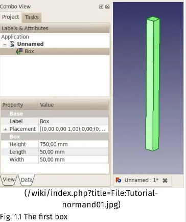
Click on the (/wiki/index.php?title=File:Part_Box.png) Box (/wiki/index.php?title=Part_Box) button to create a box
clicking it in the Project tab to the left, then
Click on the Data tab at the bottom, and change values for Height, Length and Width to 750mm, 50 and 50 (see Fig. 1.1)
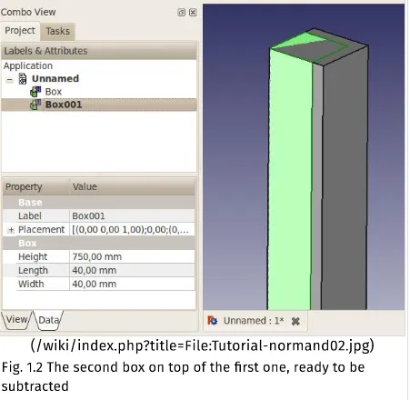
Create a second box the same way, but with values 750, 40 and 40mm. By default this box will be superimposed on the first one. (see Fig. 1.2)
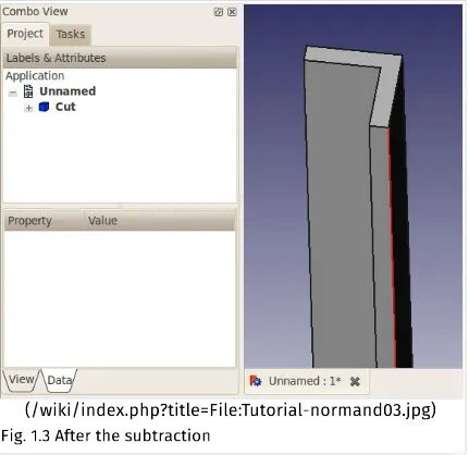
You'll now subtract the second box from the first. Select the first shape first (named Box), then the second one (named Box001), the selection order is important! (Make sure that both shapes are selected in the Project tree. One thing to remember: in Inventor navigation mode, Ctrl + click does not work for multiple selection. Switch (/wiki/index.php? title=Mouse_Model) to either CAD or Blender selection.)
On the Part Workbench toolbar, click on the (/wiki/index.php? title=File:Part_Cut.png) Cut (/wiki/index.php?title=Part_Cut) tool.
(/wiki/index.php?title=File:Tutorial-normand01.jpg)
http://www.freecadweb.org/wiki/index.php?title=Basic_modeling_tutorial 4/12
(/wiki/index.php?title=File:Tutorial-normand02.jpg)
(/wiki/index.php?title=File:Tutorial-normand03.jpg)
Fig. 1.3 After the subtraction
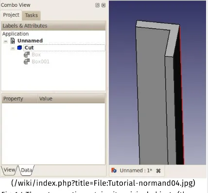
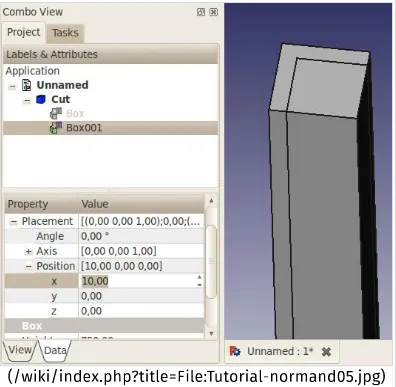
You now have your first iron angle (Fig. 1.3). You'll notice that, in the Project tab on the left, both boxes have been replaced by a "Cut" object. Actually, they're not disappeared, but rather grouped under the Cut object. Click on the + in front of it, and you'll see that both boxes are still there, but greyed out (Fig. 1.4). If you click on either of them and hit the space bar, it will show up. The space bar toggles visibility of selected objects. (Fig. 1.5)
http://www.freecadweb.org/wiki/index.php?title=Basic_modeling_tutorial 6/12
(/wiki/index.php?title=File:Tutorial-normand04.jpg)
(/wiki/index.php?title=File:Tutorial-normand05.jpg)
Fig. 1.5 You can still make the original boxes visible
http://www.freecadweb.org/wiki/index.php?title=Basic_modeling_tutorial 8/12
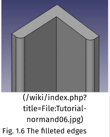
(/wiki/index.php?
title=File:Tutorial-normand06.jpg)
Fig. 1.6 The filleted edges
2nd Method - By extruding a profile
This method requires that you start by drawing a 2D profile. You need to activate the 2d Drafting workbench (/wiki/index.php? title=Draft_Workbench) (View > Workbench > 2d Draft menu).
If you haven't opened a new FreeCAD document (most of the FreeCAD window looks greyed-out), from the pull-down menu click File > New or click the Create A New Document tool (/wiki/index.php? title=File:Document-new.svg).
Next we need to set the working plane (/wiki/index.php? title=Draft_SelectPlane). Depending on your FreeCAD version, you'll have right under the toolbar, on the right, a "None" button. Click it, and on the left will appear right after "active command": Select Plane Offset, then a text field and a series of buttons. Assuming you want to start your profile on the plan view, select XY. The "None" button will now show "Top" as active plane. See note.
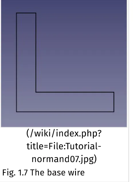
Select the (/wiki/index.php?title=File:Draft_Wire.png) Wire (multiple-point line) (/wiki/index.php?title=Draft_Wire) tool, then start drawing a shape, using the text fields for X and Y positions. The "Relative" box should be checked, as well as the "Filled" box.
1st point: 0,0
2nd point: 50,0 3rd point: 0,10 4th point: -40,0 5th point: 0,40 6th point: -10,0
No 7th point, rather click on the "Close" button to close the profile. You should now have this profile, titled "Wire" in the Project tab:
(/wiki/index.php?
title=File:Tutorial-normand07.jpg)
Fig. 1.7 The base wire
Hit the zero key on the numpad to set the view to axonometric.
Activate the Part Workbench (/wiki/index.php?title=Part_Workbench).
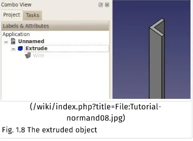
Click on the (/wiki/index.php?title=File:Part_Extrude.png) Extrude (/wiki/index.php?title=Part_Extrude) tool.
http://www.freecadweb.org/wiki/index.php?title=Basic_modeling_tutorial 10/12
Fig. 1.8 The extruded object
This method has a minor caveat compared to the other one: to edit the shape, you need to edit the Wire, it's not as easy to do as the previous method.
And there are a few other ways to do it too! I hope these two examples get you started. You'll sure hit some snags along the way (I did when I first learned FreeCAD, and I do have 3D CAD experience), but don't hesitate to ask questions on the FreeCAD forum (http://forum.freecadweb.org)!
Note on Draft working plane button:
(/wiki/index.php?
The above instructions will work, no matter what label your button has.
Kategori
(/wiki/index.php?title=Special:Categories):
Tutorials (/wiki/index.php?title=Category:Tutorials)User Documentation (/wiki/index.php?