PROCEEDINGS OF THE INTERNATIONAL WORKSHOP ON RECENT ADVANCES OF DEEP FOUNDATIONS (IWDPF07), PORT AND AIRPORT RESEARCH INSTITUTE, YOKOSUKA, JAPAN, 1–2 FEBRUARY, 2007
Advances in Deep Foundations
Editors
Yoshiaki Kikuchi
Port & Airport Research Institute, Yokosuka, Japan
Jun Otani
Kumamoto University, Kumamoto, Japan
Makoto Kimura
Kyoto University, Kyoto, Japan
Yoshiyuki Morikawa
Port & Airport Research Institute, Yokosuka, Japan
Taylor & Francis is an imprint of the Taylor & Francis Group, an informa business
© 2007 Taylor & Francis Group, London, UK
All rights reserved. No part of this publication or the information contained herein may be reproduced, stored in a retrieval system, or transmitted in any form or by any means, electronic, mechanical, by photocopying, recording or otherwise, without written prior permission from the publishers.
Although all care is taken to ensure integrity and the quality of this publication and the information herein, no responsibility is assumed by the publishers nor the author for any damage to the property or persons as a result of operation or use of this publication and/or the information contained herein.
Published by: Taylor & Francis/Balkema
P.O. Box 447, 2300 AK Leiden, The Netherlands e-mail: [email protected]
www.balkema.nl, www.taylorandfrancis.co.uk, www.crcpress.com
ISBN 13: 978-0-415-43629-8 (hbk)
This edition published in the Taylor & Francis e-Library, 2007.
“To purchase your own copy of this or any of Taylor & Francis or Routledge’s
collection of thousands of eBooks please go to www.eBookstore.tandf.co.uk.”
Advances in Deep Foundations – Kikuchi, Otani, Kimura & Morikawa (eds) © 2007 Taylor & Francis Group, London, ISBN 978-0-415-43629-8
Table of contents
Preface
IX
Organizing Committee & Research Committee
XI
Keynote lectures
Recent research into the behaviour of jacked foundation piles 3
D.J. White & A.D. Deeks
Centrifuge modelling of pile foundation 27
C.F. Leung
Advanced modeling tools for the analysis of axially loaded piles 49
R. Salgado, M. Prezzi & H. Seo
CPT-based design of displacement piles in siliceous sands 69
B.M. Lehane, J.A. Schneider & X. Xu
Recent advances in designing, monitoring, modeling and testing deep foundations in
North America 87
C. Vipulanandan
Current design practice for axially loaded piles and piled rafts in Germany 101 C. Vrettos
Recent advances in the analysis of pile foundation in China 115
M. Huang, F. Liang & Z. Li
Current status of deep and pile foundations in Korea 125
S. Jeong, C. Cho, D. Seo, J. Lee, H. Seol, Y. Kim & J. Lee
Trend of research and practice of pile foundations in Japan 143
T. Matsumoto, P. Kitiyodom & T. Shintani
Technical papers
Axial and lateral bearing capacity of piles
Vertical bearing capacity of large diameter steel pipe piles 177
Y. Kikuchi, M. Mizutani & H. Yamashita
Back analysis of Tokyo port bay bridge pipe pile load tests using piezocone data 183 J.A. Schneider, D.J. White & Y. Kikuchi
Pile foundation design of the connecting bridge for New-Kitakyushu airport 195 H. Ochiai, N. Yasufuku, Y. Maeda & S. Yasuda
Numerical prediction of long-term displacements of pile foundation 203
K. Danno, K. Isobe & M. Kimura
Side resistance of piles considering strain levels 211
Evaluation of vertical and lateral bearing capacity mechanisms of pile foundations using X-ray CT 217 K. Morita, J. Otani, T. Mukunoki, J. Hironaka & K.D. Pham
Dynamic and static horizontal load tests on steel pipe piles and their analyses 225 P. Kitiyodom, T. Matsumoto, K. Tomisawa, E. Kojima & H. Kumagai
New types of pile construction methods
Press-in piling technology: Development and current practice 233
M. Motoyama & T.L. Goh
Centrifuge modelling of the base response of closed-ended jacked piles 241
A.D. Deeks & D.J. White
Development on battered pile with screw pile method (NS-ECO pile) 253
A. Komatsu
BCH method applicable to the construction under overhead restrictions 259
S. Tajima, T. Yoshikawa, S. Saito, H. Kotaki & M. Koda
Mechanical joint “KASHEEN” for large-diameter steel pipe piles 267
G. Mori & H. Tajika
New types of deep foundations
Vertical bearing capacity of bored pre-cast pile with enlarged base considering
diameter of the enlarged excavation around pile toe 277
K. Kobayashi & H. Ogura
Seismic performance of a group-pile foundation with inclined steel piles 285
K. Okawa, H. Kamei, F. Zhang & M. Kimura
Development of design method for a soft landing breakwater with piles 291
Y. Kikuchi
Settlement and load-sharing of a piled raft foundation combined with grid-form
soil-cement walls on soft ground 299
K. Yamashita & T. Yamada
Earthquake resistant reinforcement method for pile foundations using effect of confinement of
ground solidification body 307
Y. Adachi, K. Urano, T. Takenoshita, N. Tanzawa & M. Kawamura
A design approach for composite ground pile and its verification 313
K. Tomisawa & S. Miura
A study of reinforcing methods for existing bridges on soft ground with a
solidification improvement 321
H. Fukada, K. Kato, N. Segawa, T. Ooya & Y. Shioi
Development of sheet-pile foundation combining footing with sheet-piles 327
H. Nishioka, M. Koda, J. Hirao & S. Higuchi
Recent technology development of steel pipe sheet pile foundation in Japan 335 T. Katayama
Development of three-dimensional frame analysis method for H-joint
Steel Pipe Sheet Pile foundation system 341
M. Kimura, K. Isobe & Y. Nishiyama
Application of highcapacity micropiles for seismic retrofitting in Japan 355 Y. Otani & M. Hoshiya
Field experiment on installation of suction foundation 361
H. Yamazaki, H. Yoshinaga & K. Kaneda
Sample of proposal in consulting services using new technology/methods 367
M. Komatsu
Ground improvement
Bearing capacity and settlement behavior of the spread foundation building on improved
ground by non-vibratory sand compaction pile method 373
H. Yoshitomi, T. Ohnishi, Y. Yoshinari & T. Umeno
Centrifuge model tests on deep mixing column failure under embankment loading 379 M. Kitazume & K. Maruyama
Load transfer and failure mechanisms in the reinforced ground beyond vertically loaded pile 385 J. Hironaka, T. Hirai, Y. Watanabe & J. Otani
Ground improvement for the second phase construction of Kansai International Airport 389 Y. Morikawa, T. Tabata & T. Emura
Seismic design and seismic problems
Seismic design specifications for Japanese highway bridge deep foundations against
large earthquakes 397
M. Shirato & S. Nakatani
New seismic design concept for port facilities 403
T. Sugano & T. Tanaka
Centrifuge tests on pile foundation-structure systems affected by liquefaction-induced
soil flow after quay wall failure 409
T. Tazoh, M. Sato, G. Gazetas & J. Jang
Mechanical behaviors of sandy ground during or after liquefaction 417
B. Ye, A. Yashima, G.L. Ye & F. Zhang
Advances in Deep Foundations – Kikuchi, Otani, Kimura & Morikawa (eds) © 2007 Taylor & Francis Group, London, ISBN 978-0-415-43629-8
Preface
The emerging design methodology Reliability-Based Design has become today’s norm in Japanese structural design codes and will soon be included in the international standard codes. To meet this trend, methods for the design and construction of deep foundations have made large advances. As deep foundation construction is one of the most important and applied executions in geotechnical engineering worldwide, both research work by academics and the experience and ideas of practitioners are required to develop this field and meet future stan-dards.
The International Workshop on Recent Advances in Deep Foundations (IWDPF07, Yokosuka, Japan, 1–2 February 2007) was held to transmit the information on recent advances in deep foundations to an international audience and to provide academics and practitioners the opportunity to discuss the latest developments.
Every year more than thousand technical papers are presented at the Japanese National Conference on Geotechnical Engineering, but most of these articles are unfortunately not transmitted to other countries. As structural design codes are nowadays written with international standards, a significant amount of useful infor-mation would get lost if this inforinfor-mation would not be published in a medium that is accessible to an interna-tional audience. For this reason, the IWDPF07 workshop has been focused on collecting the contributions that present Japanese technologies and experiences which are of interest to a broad, international audience. The result of this effort, this proceedings volume, comprises nine keynote lectures, prepared by outstanding inter-national experts and 34 technical papers. In addition to papers on recent research achievements and on case his-tories, a significant number of the technical papers is dealing with the practical development of deep foundations, seismic design methods, liquefaction problems, and ground improvements.
This workshop was held with the support of the Port and Airport Research Institute (PARI) and the Japanese Geotechnical Society (JGS). The research committee of JGS – “On the concept for evaluation of new technol-ogy on foundation structure design” – is the mother body of this workshop. We would like to express sincere gratitude to both organizations and the committee for their strong support of this workshop.
The editors hope that these proceedings will be interesting and fruitful to researchers and practitioners who are active in the development of deep foundation design methods and construction methods.
Advances in Deep Foundations – Kikuchi, Otani, Kimura & Morikawa (eds) © 2007 Taylor & Francis Group, London, ISBN 978-0-415-43629-8
Organizing Committee
Co-Chairmans
Dr. Yoshiaki Kikuchi, Port & Airport Research Institute Prof. Makoto Kimura, Kyoto University
Secretary
Dr. Yoshiyuki Morikawa, Port & Airport Research Institute Members
Prof. Jun Otani, Kumamoto University
Dr. Masahiro Shirato, Public Works Research Institute
Dr. Kouichi Tomisawa, Civil Engineering Research Institute for Cold Region Dr. Hisashi Fukada, Fudo Tetra Corporation
Dr. Ken-ichi Horikoshi, Taisei Corporation Mr. Masataka Tatsuta, Nippon Steel Corporation
Research Committee on the Concept for Evaluation of New Technology on
Foundation Structure Design (JGS)
Chairman
Prof. Makoto Kimura, Kyoto University Secretary
Dr. Hisashi Fukada, Fudo Tetra Corporation Members
Mr. Jiro Fukui, Public Works Research Institute
Dr. Yozo Goto, National Research Institute for Earth Science and Disaster Prevention Mr. Motohisa Hara, Penta-Ocean Construction
Dr. Ken-ichi Horikoshi, Taisei Corporation Mr. Akio Inoue, Obayashi Corporation
Dr. Yoshiaki Kikuchi, Port & Airport Research Institute Dr. Masayuki Koda, Railway Technical Research Institute Mr. Masataka Komatsu, Japan Bridge & Structure Institute, Inc Mr. Yoshinobu Miura, Kyushukensetsu Consultant
Dr. Katsunori Okawa, Mitsubishi Heavy Industries, Ltd. Prof. Satoru Ohtsuka, Nagaoka University of Technology Prof. Jun Otani, Kumamoto University
Dr. Masahiro Shirato, Public Works Research Institute Mr. Shinichi Tajima, Kajima Corporation
Mr. Masataka Tatsuta, Nippon Steel Corporation Dr. Takashi Tazoh, Shimizu Corporation
Mr. Kouichi Tomisawa, Civil Engineering Research Institute for Cold Region Mr. Kiyoshi Yamashita, Takenaka Corporation
Advances in Deep Foundations – Kikuchi, Otani, Kimura & Morikawa (eds) © 2007 Taylor & Francis Group, London, ISBN 978-0-415-43629-8
1 INTRODUCTION
1.1 Motivation for pile jacking technology The expansion of urban development into increas-ingly marginal sites, and the invention of new pile construction techniques, make the economics of deep foundations increasingly attractive. Recent techno-logical improvements have led to a proliferation of pile types and installation methods. Displacement piles, driven into the ground by hammering or vibration, remain widely used for offshore and nearshore foun-dations. For onshore foundations, non-displacement piles have increased in popularity during the past 50 years since these can be installed without the noise and vibration associated with conventional methods of pile driving.
Increasingly stringent environmental legislation now precludes the use of pile hammers in urban areas, and restricts the disposal of spoil created by the con-struction of conventional bored piles. In response, alternative construction methods for pile foundations have evolved. These developments have been driven by a desire either to improve the performance of the foundation or to reduce the environmental impact of its construction. Performance is quantified by the strength and stiffness of the foundation. Noise, ground vibrations and spoil material (particularly from urban brownfield sites) all have negative environmental impacts.
One such new construction technique is pile jacking, which is the subject of this review paper. Pile jacking has historically been used for the construction of small foundation piles, as are used for minor underpinning works. More recently, high-capacity jacking machines have been developed, which offer the opportunity for the foundations of large buildings or heavy structures to be installed without the noise and vibration associated with conventional methods of displacement piling. Some pile jacking systems can be supported on the pile wall under construction, rather than a piling mat, which reduces the need for temporary works leading to shorter construction schedules and reduced material use.
For displacement piles, the installation method – jacking, or dynamic driving – has an effect on the deformation of the soil during installation, and the resulting stress field around the pile. In turn, these fac-tors affect the pile behaviour during subsequent load-ing. In design practice, the effect of installation method is rarely considered when assessing the response of a pile foundation. In some cases, design codes and research papers recommend empirical factors to differ-entiate between the capacity of bored and driven piles (e.g. Bustamanate & Gianeselli 1982, De Beer 1988, Ghionna et al. 1993) but as pile jacking is a relatively new technology little advice exists for predicting the behaviour of jacked piles.
In addition to the short-term impact of noise and vibration during the construction process, the
Recent research into the behaviour of jacked foundation piles
D.J. White
Centre for Offshore Foundation Systems, University of Western Australia, Perth, Australia Cambridge University Engineering Department, UK
A.D. Deeks
Cambridge University Engineering Department, UK
environmental impact of foundation construction extends to the energy and resource use prior to instal-lation, and subsequent to the initial working life of the foundation. If dynamic installation is discounted in urban areas due to the unacceptable ground vibra-tions, the choice between jacked or bored installation methods is linked to the choice between steel or con-crete piles. The extraction and re-use of steel piles, which is made possible by pile jacking rigs, reduces the whole life cost of this type of foundation (Dawson, 2001, Chau et al. 2006).
If the environmental benefits of pile jacking are to become more widely exploited, research into the influence of installation method on pile behaviour must be disseminated amongst practitioners to estab-lish this knowledge in engineering practice.
This paper reviews recent research into the behav-iour of piles installed by jacking. The following topics are covered:
1. Pile jacking technology and the environmental impact of pile jacking compared to alternative pile construction techniques;
2. Recent research into the fundamental mechanisms underlying the installation and loading of dis-placement piles;
3. Recent guidance for predicting the axial capacity and load-settlement response of piles, with emphasis on the differences between driven and jacked piles;
4. Recent research into the use of H-piles, focussing on differences in behaviour of jacked and driven piles due to plugging.
A significant proportion of the research reported in this paper is related to the ‘press-in’ method of pile jacking, reflecting the authors’ experiences in a long-term research programme at the University of Cambridge supported by Giken Seisakusho Co. Ltd. However, key outcomes from other major research projects into jacked piles are also reported.
1.2 Machine development
Pre-formed displacement piles can be installed by static jacking force alone if sufficient reaction force is available. Small rigs capable of pushing micro-piles into the ground for underpinning are in wide use. Reaction force is usually provided by the weight of the structure being underpinned.
Modern pile jacking machines operate by pushing the pre-formed pile – made from steel or precast con-crete – into the ground with hydraulic rams, using static force alone. Reaction is provided either by kent-ledge (deadweight) or by gripping the heads of adja-cent piles that have already been installed.
The first large pile jacking machine was the Taylow Woodrow ‘Pilemaster’, which was developed
in the UK in 1960 for the installation of sheet piles. This machine stood on top of a row of sheet piles, and gained reaction from a pair of piles on either side of the pile currently being jacked downwards.
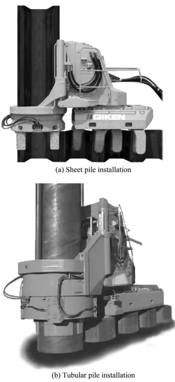
The first machine of the type now referred to as a ‘Silent Piler’ was produced by Giken Seisakusho Co. Ltd. in 1975. This type of machine ‘walks’ along the row of piles under construction, gaining reaction by gripping the previously-installed piles – an approach which has been termed the ‘press-in method’. Different types of Silent Piler are capable of installing sheet piles (Fig. 1a), tubular piles (Fig. 1b) or precast concrete piles.
conventional piling rig, as used by the 2 MN capacity ‘Push-pull’ system produced by Dawson Construc-tion Plant Ltd, UK (Fig. 2). This system has been used for the installation of small groups of piles which act in unison as a single larger pile after construction (Filip 2006).
Since the Pilemaster, the Silent Piler and the Push-pull systems gain reaction from previously-installed piles, only closely-spaced groups of piles or continu-ous walls can be installed by these methods. An alter-native approach is to gain reaction force from either the deadweight of the machine, additional ballast or temporary ground anchors.
The use of a deadweight-reaction pile jacking machine was reported in Russia by Goncharov et al. (1964) (Fig. 3). The 350 kN weight of the tractor units of this machine was used as reaction force to drive precast concrete piles into clayey soils. More modern pile jacking machines that rely on kentledge for reac-tion are manufactured by Tianhe Machinery Ltd, China, and have been exported to Malaysia and Australia, where they are known as the ‘G-pile’ system (Fig. 4). The jacking unit of this machine can move horizontally within the footprint of the ballast, so multiple piles can be installed without unloading the deadweight.
The largest pile jacking machines of the Silent Piler type have a jack capacity of ⬃4 MN but weigh only ⬃400 kN. The largest Silent Pilers can install tubular piles of up to ⬃1.5 m diameter in strokes of length ⬃1 m. The largest G-pile machine has a jacking capacity (and a deadweight) of ⬃9 MN and can install
400 mm square precast concrete piles in 1.8 m jack strokes. When comparing these systems, the additional jacking capacity of the G-pile machine is offset by the operational complexity of moving 900 tonnes of dead-weight around a site. A substantial piling mat is needed for soft ground sites. The mean bearing pressure exerted by the fully loaded 9 MN G-pile machine dur-ing movement of the jackdur-ing unit is ⬃300 kPa. In con-trast, the ‘self-walking’ feature of the Silent Piler system extends to specially-designed pitching cranes and power packs. The resulting system requires no temporary works since all equipment is supported on the pile wall under construction (Fig. 5).
1.3 Applications of pile jacking
Most current design guidance for the axial and lateral response of piles has been derived from experience with dynamically driven or bored piles. As new installation Figure 2. ‘Push-pull’ rig-mounted pile jacking unit (Filip
2006).
Figure 3. Early Russian jacking unit (Goncharov et al. 1964).
techniques have been developed, such as pile jacking, designers are required to assess whether current guidance is applicable, or whether modified methods are appropriate to reduce risk or exploit improved performance.
The installation method of a pile determines the stress state and level of disturbance of the soil imme-diately surrounding the pile, as described in Section 3 of this paper. These stresses and disturbance have a significantly influence on the axial response of the pile under working conditions. In contrast, the instal-lation method has less effect on the lateral response of the pile. During lateral loading, the strength of more distant soil is mobilised, which is unaffected by the installation method.
Therefore, jacked piles have been widely adopted for laterally-loaded applications such as retaining walls supporting river banks and excavations, designed by conventional methods. Long linear projects, such as riverbank reinforcement, are particularly suited to ‘self-walking’ pile jacking systems due to the elim-ination of temporary works. Case studies describing recent applications of pile jacking systems for appli-cations involving lateral loading are reported by Dubbeling et al. (2006).
In contrast, for axially-loaded applications, such as building or bridge foundations, designers have been cautious in adopting pile jacking technology, due to concerns that the installation procedure may not lead to the same capacity as conventional dynamic instal-lation methods. This uncertainty has been reduced by recent research programmes involving axial load test-ing of jacked piles.
Recent case studies in which jacked piles have been used to support axial loads are reported by Li et al. (2003), Mitchell & Mander-Jones (2004), White et al. (2003), Filip (2006) and Lehane et al. (2003).
A beneficial feature of pile jacking is that the installation force provides an indication of the static bearing capacity during subsequent loading. As dis-cussed later, it is important to recognise that consoli-dation and ‘set-up’ can cause changes in capacity after installation. Usually these effects lead to an increase in capacity, but in certain circumstances a loss of strength has been observed. Most pile jacking systems include direct measurement of the applied jack load during installation, and some systems have specific features to allow static maintained load tests to be conducted after installation, providing verifica-tion of the pile performance.
An additional requirement in order for jacked piles to be adopted for axially-loaded applications is the need for new acceptance or termination criteria in regions where the capacity of a pile must be con-firmed at the completion of driving. Hammer-driven piles are conventionally installed to a specified set per blow as confirmation – based on a dynamic pile driv-ing analysis – that the design capacity and stiffness requirements have been met.
2 ENVIRONMENTAL IMPACT 2.1 Noise emissions
Noise emissions on construction sites present a health hazard to site operatives and cause annoyance to neighbours. Noise levels are expressed in decibels, which are related to the fluctuating air pressure, p (Equation 1).
Noise levels typically decrease with the logarithm of radius, r, from their source, due to spherical geo-metric spreading. The noise level of a source, Nsource,
can be attenuated using Equation 2 to deduce the noise level, N, at a remote point (Sarsby 2000).
Guidance on acceptable noise levels during con-struction is given by British Standard BS5228 (1992). In urban areas N should not exceed 75 dB at the out-side of a noise sensitive building such a reout-sidential or office building. In rural areas a lower limit of 70 dB applies.
isolation systems. In Figure 6, various environmental noise levels are compared with the source noise levels,
Nsource, of typical piling equipment, including recent
‘quiet’ hammers and pile jacking machines. The human ear perceives a 10 dB increase in noise level as a doubling in loudness so the logarithmic scale obscures the true variation.
By plotting the theoretical attenuation of noise with distance (Equation 2), an indication of the min-imum acceptable separation is found. Modern ‘quiet’ hammers are rarely acceptable in congested urban areas, but are increasingly used for new-build devel-opments, where the minimum separation limits can be satisfied. The noise emissions from pile jacking machines do not exceed ambient urban noise.
2.2 Ground vibration
Design codes specify limits on the permissible ground vibrations from construction operations. These limits are intended to prevent disturbance to people and damage to nearby structures. The limits preclude the use of conventional dynamic piling methods in certain locations, particularly urban areas.
Ground vibrations are usually quantified by the peak velocity of particles in the ground as they are disturbed by the passing wave. The instantaneous particle velocity consists of three orthogonal components which are usu-ally measured independently using a triaxial geophone. The most commonly used definition of peak particle velocity is the simulated resultant ppv. This is the vector sum of the maximum of each component regardless of
whether these component maxima occur simultan-eously (Hiller & Hope, 1998).
Eurocode 3 (1992) provides guidelines for accept-able human exposure to ground vibrations depending on the length of the construction period (Fig. 7a). Structural damage thresholds are also specified, ran-ging from a ppv of 2 mm/s for buildings of architectural merit, to 15 mm/s for industrial buildings (Fig. 7b).
Ground vibration measurements near to pile jack-ing operations have been reported by Li et al. (2003), Rockhill et al. (2003) and White et al. (2002) (Fig. 8). The primary source of these vibrations is the elastic rebound of the pile head when the jacking load is released at the end of each stroke. If the pile is deviat-ing durdeviat-ing installation, lateral vibration can result in addition to upwards movement.
Good operational practices can reduce these sources of ground vibration. For example, the Silent Piler sys-tem allows the jacking force to be reduced in a con-trolled manner at the end of a downstroke, and a skilled operator can correct for any deviation before releasing the pile head. Figure 9 shows the time record of ground vibrations during installation of a sheet pile using a Silent Piler jacking machine. Negligible vibra-tions are recorded whilst the pile is moving but four transient pulses are evident between jacking strokes. The largest of these events correspond to the opening and closing of the chuck that grips the pile, and from Figure 6. Noise limits and emissions from piling operations.
the impulse of hydraulic force at the start of the jack-ing stroke.
For comparison, a database of previously pub-lished measurements of ground vibrations during dynamic piling is shown in Figure 10 (Head & Jardine, 1992). Figures 7–8 and 10 are plotted on iden-tical axes. The measured ground vibrations reduce in an approximately linear fashion with log radius. A number of empirical methods for predicting ground vibrations follow this trend, taking the general form of
Equation 3 (Attewell & Farmer (1973), BS5228 (1992), Eurocode 3 (1992)).
The constant A in Equation 3 depends on the proper-ties of the medium and the initial energy of the wave. If the medium is non-dissipative, the index n refers to the geometry of the wavefront. Geometric spreading of a cylindrical wavefront leads to n⫽0.5, whilst for
geometric spreading from a point source n⫽1.
Empirical guidance for the selection of A for dynamic pile driving methods is given by Eurocode 3 (1992), based on hammer energy and soil type. A value of n⫽1 is recommended, reflecting that at relevant
dis-tances from the pile, the upper portion from which the vibrations radiate is best idealised as a point source.
For the jacked pile data shown in Figure 8, Rockhill et al. (2003) proposed a bilinear fit as a sim-ple predictor for ground vibrations induced by pile jacking, linking ppv to the log of separation, r (Equation 4). Close to the pile, the bilinear fit uses an index of n⫽0.5, reflecting that the pile is better
rep-resented as a line source at this close proximity. Further away, the index reverts to n⫽1, indicative of
spherical geometric spreading.
By combining Equation 4 with the Eurocode 3 limits, an indication of the minimum separation between pile jacking and sensitive structures can be assessed. For residential structures this intersection corresponds to Figure 8. Ground vibrations near pile jacking operations.
Figure 9. Ground vibration measurements during sheet pile installation using a Silent Piler jacking machine.
a nominal separation of around 0.5 metres. However, for practical purposes, the minimum separation is more likely to be limited by logistical constraints than the transmission of ground vibrations. For a separa-tion greater than a few metres, the ground vibrasepara-tions from pile jacking are indistinguishable from vibra-tions arising from passing traffic and other construc-tion plant such as generators.
2.3 Sustainability: material and energy use In urban areas the most commonly-used pile material is concrete, due to the low cost of bored piling and the unsuitability of pile hammers. The recent introduction of high capacity jacking machines has made steel piles a feasible solution for urban areas, and the choice between steel and concrete is once again available.
As raw materials become scarcer, and environmen-tal concerns related to excessive energy use emerge, the choice between steel and concrete is increasingly influenced by environmental factors. In certain regions, these factors are having an increasing effect on the economics of construction through environmental taxes imposed by legislation.
Unlike concrete, steel piles can be easily recycled, although re-use in situ remains an option (Chapman et al. 2001). Embodied energy is a common indicator used to assess the energy use of an object or structure. In the case of foundation piles, this quantity includes the energy used to extract and process the raw mater-ials, then transport and install the foundations. For recycled steel piles the embodied energy is substan-tially reduced.
Chau et al. (2006) describe a case study comparing the embodied energy of steel and concrete retaining wall systems. For the conditions considered, it was found that the embodied energy of a steel sheet pile wall is halved by the use of recycled steel, and is the optimal solution – from an embodied energy view-point – compared to reinforced concrete systems. Other indicators of environmental impact such as the embodied CO2emissions provide additional
indica-tors to guide material selection, although standard input parameters and procedures for life cycle analy-sis assessments are not widely established.
The facility to remove steel piles – unlike bored concrete piles – and release the site for subsequent alternative development is an additional consider-ation when comparing the long term impact of founda-tion piles (Dawson 2001).
3 INSTALLATION AND AXIAL CAPACITY 3.1 Pile – CPT analogy for design
As discussed in Section 1.3, the installation method of a pile determines the stress state and level of
disturbance of the soil, which in turn has a significant influence on the subsequent strength and stiffness under axial load. This section describes a simple framework for describing the stress changes that take place around a jacked or driven pile during installa-tion. This framework provides a simple basis on which to (i) formulate prediction methods for the strength and stiffness of jacked piles and (ii) under-stand how the installation process of a jacked pile can be optimised to maximise the axial strength and stiff-ness (or reduce the required jacking capacity).
Most modern pile design methods directly link CPT parameters to pile capacity, taking advantage of their similar geometry and installation processes (Fig. 11). This analogy is particularly appropriate for jacked piles, which are installed by static force – in the same way as a CPT – in contrast to the dynamic installation of driven piles.
If a jacked pile is considered analogous to a CPT, then the CPT tip resistance, qt, can be linked to the
base resistance during installation, qbf,install, and in
turn this can be linked to the subsequent static base resistance at failure qbf. The relative size of the pile
and the CPT must be accounted for, as discussed in Section 3.3. The CPT sleeve friction, fs, is analogous to
the unit shaft resistance, τsf, but correlations between
these parameters are hampered by the unreliability of sleeve friction measurements, which are often affected by wear and alignment of the sleeve, and by the reso-lution of subtraction cone devices.
Instead, it is increasingly common to link τsfto qt,
taking due account of the mechanisms that occur as the soil passes around the base of the advancing pile. Since the soil adjacent to the pile shaft, which governs τsf,
experienced the load qbf(as the pile base passed that
horizon) more recently than the in situ stress σ⬘vo, it is
more logical to estimate shaft capacity from qtthan
from σvo⬘ using a classical earth pressure method.
This approach of breaking down the stress history of a soil element during pile installation is described in detail by Poulos (1988) and White (2005), and is summarised below.
3.2 Soil element ‘life cycle’ for drained penetration (installation in sand)
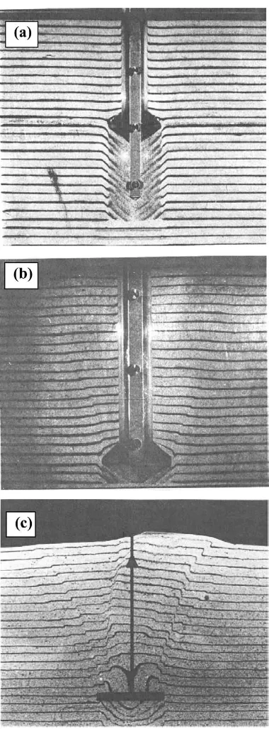
The key stages in the stress history of a soil element close to a jacked pile are illustrated in Figure 12. A simple stress path to represent these changes is given in Figure 13. These diagrams represent the case of drained installation – in a sandy soil – so neglect pore pressure effects. Each stage is described in sequence below.
3.3 Base resistance, qbf,install, qbf
3.3.1 Mechanisms linking qt, qbf,install, qbf
A soil element that will be in contact with the pile shaft after installation initially lies beneath the pile
tip. As the pile or CPT tip approaches, the local stress rises from the in situ value until a stress of qbf,installor
qtacts as the pile or CPT tip reaches that point. The
following mechanisms can lead to differences between the profiles of qtand qbf,installduring jacking, and qbf
during a subsequent load test:
(i) During installation, local heterogeneities in ground condition are smoothed out by the large size of a pile compared to a CPT. The zone of deformation around the base of a pile is larger than around a CPT, in proportion to the effective diameter of each. Measurements of qtare
there-fore more sensitive to local variations in ground condition.
(ii) The combined effects of the differences in diam-eter and penetration rate of a pile compared to a CPT may lead to different drainage conditions. The degree of drainage during steady penetration is governed by the dimensionless group vD/cv,
where v⫽penetration rate, D⫽diameter and cv
is the relevant coefficient of consolidation. The diameter of a pile is typically an order of magni-tude larger than a CPT (DCPT⫽35.7 mm),
whereas the installation rate of jacking machines is comparable to a CPT (vCPT⫽20 mm/s).
There-fore, at sites where the CPT is drained, pile instal-lation may be partially drained, causing excess pore pressure generation and a difference in pene-tration resistance compared to a CPT.
(iii) During static loading after installation, the plunging, or steady penetration resistance may Figure 12. Stages in the loading history of a soil element
adjacent to a jacked pile.
not be fully mobilised if qbfis defined by a
settle-ment criterion. However, due to the high base stiffness of jacked piles (described in Section 4), the plunging base capacity is usually mobilised at the conventional settlement criterion of D/10. 3.3.2 Field measurements linking qcand qbf,install
Field measurements at sand and clay sites generally indicate that a unit resistance similar to the CPT tip resistance is mobilised on the base of a closed-ended or plugged pile during jacked installation, such that
α⬃1 in Equation 5:
where qt,avis the CPT tip resistance, suitable averaged
over a vertical range, to account for the effect of local heterogeneities. At uniform sites a simple arithmetic average of qt over a vertical range of⫹/⫺1.5D is
widely used to derive qt,av (Randolph 2003, Jardine
et al. 2005 and White & Bolton 2005). However, Xu & Lehane (2005) show that for sites with a strongly layered stratigraphy it is more appropriate to use the ‘Dutch Method’ (Van Mierlo & Koppejan 1952, Schmertmann 1978). This method gives additional weighting to regions of weaker soil, to which the deformation during penetration will be attracted.
Field tests reported by Dingle et al. (2007) showed that the Dutch method gave a lower bound prediction
to qbf,installfor a 320 mm diameter closed-ended
tubu-lar pile at a highly layered site in Japan. Lehane et al. (2003) report measurements of qbf,installfor a 350 mm
square precast concrete pile installed through sands and silty clays. It was found that qbf,installwas ⬃80% of the raw qtprofile, but in closer agreement with qt,av
found using the Dutch method. Good agreement between qbf,install and qt has also been reported by
Chow (1997) and Lehane (1992) during installation of a 100 mm diameter closed-ended instrumented jacked pile at relatively uniform sites.
A plug usually forms within an open-ended jacked pile after a few diameters of penetration, unless spe-cial measures are used, such as vertical cycling (‘surging’), water jetting, internal augering or the use of an internal pile shoe. During further jacking the pile remains fully plugged unless a stronger layer is reached, at which point the penetration reverts to a coring manner until sufficient additional plug length is mobilised to balance the increase in base resistance (White et al. 2000, Randolph et al. 1991).
It is difficult to measure the base resistance acting on the enclosed soil plug of an open-ended pile dur-ing installation. Lehane & Gavin (2001) present measurements of annular and plug resistance during installation and load testing of a heavily instrumented model jacked pile in sand. During fully plugged
penetration, qb,plug/qc ⬃1, but reduced values are measured with increasing incremental filling ratio (IFR) (Fig. 14). This observation confirms that when the internal shaft resistance is insufficient to hold the plug in place against the steady penetration resist-ance, qt, soil flows into the pile, lengthening the plug.
After sufficient lengthening, the increased internal shaft resistance balances the penetration resistance, qt, and the incremental filling ratio reverts to zero.
Lehane & Gavin’s (2001) data of annular resist-ance, qb,ann, confirms that the full local CPT
resist-ance, qt is mobilised on the steel area of the pile
(Fig. 15). It is usual to assume the same for open-section H-section or sheet piles.
Figure 14. Plug resistance during open-ended pile jacking (Lehane & Gavin 2001).
A back-analysis by White et al. (2000) showed that a vertical arching analysis, following De Nicola & Randolph (1997), can capture the plugging behaviour of a pipe pile during jacking. However, the arching equations are very sensitive to the assumed profile of earth pressure coefficient within the soil plug. For most practical dimensions of tubular pile, a plug will form during jacking, and so the installed pile can be considered as closed-ended under subsequent static loading. This behaviour contrasts with dynamic pile installation methods, during which the inertia of the soil within the pile prevents formation of a plug (Liyanapathirana et al. 2001).
Plugging can also occur during jacking of open-section H-piles. Li et al. (2003) report cases in which jacked H-piles have buckled due to the free-standing length of pile created by downdrag of soil plugs on either side of the H-pile web (Fig. 16). Voids of depth 7–10 m have been reported around H-piles (Li et al. 2003). Sand filling around jacked H-piles is now a standard construction procedure in Hong Kong, to prevent buckling.
3.3.3 Field measurements linking qbf,installand qbf
The jacking load measured during installation is often used to verify the capacity of a jacked pile, based on the assumption that the capacity will not reduce with time after installation. It is well known that the shaft capacity of a displacement pile changes with time after installation due to consolidation and other mechanisms – a process known as ‘set-up’. Set-up of shaft resistance is discussed in Section 3.8.
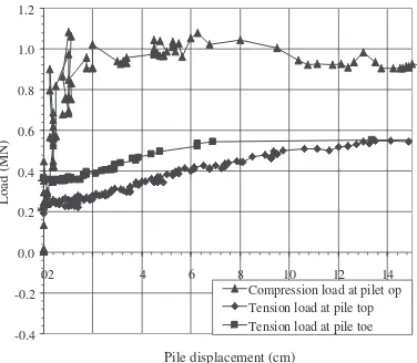
The base resistance of a pile is less affected by time-dependent processes. Dingle et al. (2007) report the re-mobilisation of qbf,installduring static load tests
conducted 1–8 hours after installation of a 320 mm diameter closed-ended jacked pile. The base capacity at failure, qbf, was found to be approximately equal to,
or greater than – for piles tipped in clay – the base resistance recorded during the final installation stroke. The average ratio of qbf(defined at a
settle-ment of D/10) and the load at the end of the final stroke of installation, qb,fs, was 0.99 for the piles
tipped in sand (Fig. 17).
However, Medzvieckas and Slizyte (2005) report cases in which the base resistance during a load test is lower than during installation – a phenomenon known as relaxation that was also observed by Mitchell & Mander-Jones (2004). This behaviour is not yet fully understood, but could be due to the development of negative pore pressures during shear if the soil is dila-tant. This negative pore pressure would create add-itional effective stress around the pile base during jacking, which would not be present immediately that the jacking force is reapplied, or during a slow main-tained load test. Mitchell (2004) describes how relax-ation was eliminated at a particular site by cyclic loading of the pile after installation.
Compared to driven piles, jacked piles exhibit a stiffer base response – and a greater base capacity if defined by a settlement criterion – due to the stiffen-ing effect of the final jackstiffen-ing stroke and the resultstiffen-ing residual base load. For closed-ended driven piles in sand, the UWA-05 design method recommends a value of α⫽0.6 in Equation 5 (Lehane et al. 2005a).
Figure 16. Plugging and buckling of an H-pile (Li et al. 2003).
This reduction factor on qt,avis primarily due to
par-tial mobilisation of the full base resistance at D/10 settlement. For closed-ended jacked piles, White & Bolton (2005) and Xu & Lehane (2005) found
α⬇0.9 for a database of load tests based on settle-ment criterion of D/10.
For open-ended driven piles, Lehane et al. (2005a) propose a linear reduction in qbf/qt,av with effective
area ratio (defined in Section 3.6) such that α:0.15
for a thin-walled pile penetrating in an unplugged manner. Since jacked pile usually plug during instal-lation, these low values of αrarely apply.
3.4 Shaft resistance: general expression
The shaft resistance on a displacement pile is gov-erned by the effective stress friction equation:
where τsfis the unit shaft resistance, σ⬘hfis the
hori-zontal effective stress on the pile shaft at failure, and
δis the pile-soil interface friction angle. To exploit the analogy between the CPT and a jacked pile, it is neces-sary to link σ⬘hf to the cone tip resistance, qt. The
stress history diagrams shown in Figures 12 and 13 provide this link, and lead to the following general expression for shaft resistance, involving the add-itional parameters a, b and c:
The mechanisms underlying parameters a, b and c are described in Sections 3.5–3.7.
3.5 Flow around pile tip: ‘a’ parameter
During installation of a closed-ended jacked pile, as an element of soil flows around the shoulder of the pile the stress level drops from qbf,install(or qt) to some
fraction of this value. This fraction depends on the deformation properties of the soil, and in particular the unloading stiffness. As the soil element comes into contact with the lower part of the pile shaft, an upwards shear stress is mobilised. This maximal value of unit shaft resistance is denoted τs,max. On the
simplified stress path, this stage is marked A – C (Figs. 12, 13) and τs,maxcan be linked to the cone
resistance as follows:
For the case of a CPT, τs,maxis similar to the sleeve
resistance, fs, although fsis actually the average shear
stress over ⬃3 diameters behind the tip of a standard cone. The CPT friction ratio Fr⫽fs/qtis typically 1% in
sands, indicating that a/tan δ⬃100 for the stress path around a smooth CPT (δ⬃20°), suggesting an ‘a’ parameter of ⬃30. In clays, which have a lower stiffness than sands, so unload less whilst passing around the pile tip, Fris ⬃5%, which corresponds to a correspondingly lower ‘a’ parameter. Values of a⫽33 and 44 for
com-pression and tension loading respectively are recom-mended in the UWA-05 design method for driven piles in sand (Lehane et al. 2005a). It is assumed that these values also apply for jacked piles. Schneider et al. (2007) discuss in more detail how the ‘a’ parameter varies with soil type. The difference between compres-sion and tencompres-sion loading can be attributed to Poisson’s strains in the pile and the general unloading of the ground during uplift (de Nicola & Randolph 1993).
3.6 Effective area ratio, Ar: ‘b’ parameter
Field-scale open-ended piles rarely plug during driving due to the inertia of the soil column. The pile usually penetrates in an unplugged (‘coring’) manner instead. In contrast, jacked piles often plug during installation, creating additional soil displacement and horizontal stress acting on the pile shaft. This effect leads to differences in the behaviour of jacked and driven piles.
The degree of plugging during an increment of penetration can be quantified by the effective area ratio, Ar,eff, which is the ratio of the total volume of
material added to the ground (i.e. the gross pile vol-ume minus any soil entering the plug) to the gross pile volume.
Ar,eff⫽1 corresponds to plugged penetration or a
closed-ended pile. Ar,eff⫽0 corresponds to a
vanish-ingly thin-walled pile for which there would be negli-gible soil displacement. The incremental filling ratio (IFR) is the incremental change in plug height (∆hp)
with incremental increase in embedment depth (∆zbase), IFR⫽∆hp/∆zbase.
A multiplicative factor, Ab
r,eff is included in
Equation 7 to account for the effect of plugging. The difference in shaft resistance on an open-ended pile compared to a closed-ended pile, due to the differing level of soil displacement, is therefore:
(2005) show that a value of b⫽0.3 is appropriate for
sands (drained expansion), whilst a lower value of b ⬃0.1 is more appropriate for clays (undrained expan-sion) (Carter et al. 1980). For a typical thin-walled pipe pile (D/t⫽50), Equation 10 predicts increases
in shaft resistance by factors of 2.1 and 1.3 in sand and clay respectively if plugging occurs. Experimental corroboration of this analysis is provided by Gavin & Lehane (2003), who report a factor ⬃2.5 difference in unit shaft resistance on a model pipe pile when plugged compared to unplugged.
The purpose of these examples is to highlight the possible increase in shaft resistance that can result from permitting a pipe pile to plug during jacked installation. However, site practice is often to prevent plugging by lubricating the inside of the pile or adding a driving shoe, in order reduce the jacking resistance and ease installation. The possible benefi-cial effect of plugging cannot be utilised in design if plugging is subsequently eliminated by site practices.
3.7 Friction fatigue: ‘c’ parameter 3.7.1 Friction fatigue stress path stage
As a pile is jacked or driven, cycles of loading are applied to the soil adjacent to the pile – as illustrated by stage D on Figures 12 and 13. Jacking involves predominantly one-way cycles of loading, although two-way cycles result if residual base load is trapped after each jacking stroke, leading to the mobilisation of negative shaft resistance. After the final jacking stroke, or hammer blow, some base load may be retained by negative shaft friction on the upper part of the pile, leaving the soil at stress state E. This simple stress path ignores the possible generation of excess pore pressures, but serves to highlight the influence of cycling on σ⬘h. Cycles of loading lead to a
reduc-tion in normal stress and available shaft resistance – a phenomenon known as friction fatigue. This mecha-nism has been quantified in laboratory tests, cen-trifuge models and at field scale.
3.7.2 Laboratory test evidence of friction fatigue The cyclic loading of each soil element adjacent to the pile shaft is analogous to the response observed in cyclic interface shear box (or ring shear) tests. Cyclic interface shear of sand leads to gradual densification of the shear zone, even if the sample originates in a dense state (DeJong et al. 2003, Porcino et al. 2003 and Ghionna & Mortara 2002). Kelly (2001) describes four tests on sand using the 1 m diameter ring shear apparatus at Sydney University. These results high-light the effect of cycling on interface behaviour (Fig. 18). After initially dilating, each sample contin-ues to shear at constant volume, until 10 displacement-controlled cycles are applied. The number of cycles
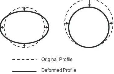
has a greater influence on the contraction of the inter-face layer than the net displacement. Also, a higher amplitude of cycling leads to greater contraction. 3.7.3 Centrifuge tests showing friction fatigue On piles, this behaviour is termed ‘friction fatigue’ and causes the progressive reduction in unit shaft resistance at a given soil horizon as the pile penetrates deeper through further cycles of loading (White & Bolton 2002 and Randolph 2003). Adjacent to the pile, changes in the interface layer thickness, ∆t, cause changes in horizontal stress, ∆σ⬘h. These changes depend on the constraint provided by the far field soil, which can be idealised as an elastic cylindrical cavity (Fig. 19, Equation 11):
where G is the operative elastic stiffness of the sur-rounding soil. ∆t is the contraction of the interface
layer. Contraction of the interface leads to a reduction in σ⬘h, as shown schematically in Figure 19.
Model tests using instrumented piles confirm that friction fatigue is driven by cycles of loading, and that the decay in shaft resistance along a pile shaft is best normalised by the number of cycles experienced by that element, rather than the distance from the pile tip, h. Centrifuge tests involving artificial monotonic pile installation – to the final depth in a single-stroke – show identical values of horizontal stress acting on the pile over the range 1⬍h/D⬍9 (Fig. 20). However,
the horizontal stress decays when cycles of loading are applied, either during installation, or in a subse-quent load test (White & Lehane 2004). Similar data is presented by Schneider & Lehane (2006) and CPT tests using multiple friction sleeves confirm this behaviour (DeJong 2001).
3.7.4 Field scale tests illustrating friction fatigue At field scale, the instrumented driven pile tests by Vesic (1970) can be compared with the jacked pile
tests reported by Lehane (1992) and Chow (1997) to show the effect of cycles on mean shaft resistance (Fig. 21). These two sets of tests, both on 100 mm diameter closed-ended steel piles, show twice as much shaft resistance for jacked installation com-pared to dynamic driving.
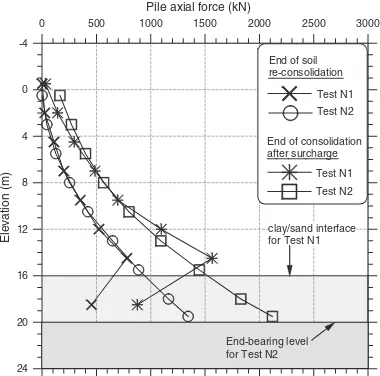
The instrumented pile tests reported by Dingle et al. (2007) isolated the effect of cycles on mean shaft resistance by installing the same pile at the same site with different numbers of jacking strokes. Figure 22 illustrates the strong influence of installation cycles on mean shaft resistance. The 10 m long piles could be installed with as few as 12 one-way jacking cycles, leading to a mean normalised shaft resistance of [τsf/qt]av⫽0.006 However, if installation involved a
larger number of cycles, with two-way displacement, the shaft resistance halved.
The mechanism of friction fatigue is well known to operators of pile jacking machines. Large cycles of vertical displacement are commonly used to ease Figure 19. Friction fatigue mechanism (White & Bolton
2004).
Figure 20. Horizontal stress measurements on a model jacked pile during monotonic installation (White & Lehane 2004).
installation – a technique known as ‘surging’. Machine operators often aim to reduce the required jacking force in order to counter the tendency for sheet piles to deviate from vertical during hard driving.
Figure 23 shows the effect of ‘surging’ on the jack-ing force required to install a sheet pile at a sandy site. In test 4 the pile was installed to a depth of 10 m by one-way jacking strokes of ⬃700 mm length. In test 5 the pile was cycled by 350 mm after each jacking stroke. These 13 additional displacement cycles reduced the jacking force by 50% at the final embed-ded depth.
At a different site, with clay layers, the same sur-ging procedure led to a smaller reduction in jacking force of only 10–20 % (Fig. 24). This comparison illustrates that surging is less effective in clay since friction fatigue is reduced. In clay, the pile-soil inter-face shear zone is thinner than for sand, so can undergo less contraction. In addition, this contraction is hindered by the low permeability which prevents the escape of pore water.
This strong influence of loading cycles on friction fatigue has implications for the design of jacked piles. Compared to driven piles – which are installed by many hundreds of two-way cycles – jacked pile
installation involves 10–100 cycles of loading, which is predominantly one-way.
However, although measurements indicate that friction fatigue is caused by cycles of loading, it is not straightforward to include number of cycles – accounting for their amplitude and nature (one-way or two-way) – within a design method. Experimental evidence shows that the rate of friction fatigue depends not only on the number of imposed cycles, but on the mode and amplitude of cycling – which are machine and operator dependent. Two-way cycling leads to a greater degradation than one-way cycling during installation.
These effects are acknowledged in the analysis of in-service cyclic loads – for example during storm loading of offshore piles (Poulos 1988, Jardine 1991). These effects also occur during installation-induced cycles, so affect the resulting shaft capacity and should be acknowledged in design.
3.7.5 Friction fatigue: design approach
A pragmatic approach for design is to follow the for-mat of current CPT-based methods for driven piles. These methods account for friction fatigue through a reduction in unit shaft resistance in proportion to (h/D)c, with a maximum value of h/D being applied
very close to the pile tip (typically over the bottom two diameters):
For dynamically-driven piles in sand, a friction fatigue index of c⫽ ⫺0.5 is recommended by Lehane
et al. (2005a) in the UWA-05 design method, based on a database of⬎75 pile load tests. The lower number of
cycles imposed during installation of a jacked pile leads to a smaller value of the index c. The horizontal stress measurements shown in Figure 20 imply that c⫽0 for steady – monotonic – penetration. For piles
Figure 22. Influence of jacking cycles on shaft resistance (Dingle et al. 2007).
Figure 23. Effect of ‘surging’ on jacking force at sandy site.
installed with a realistic number of jacking strokes, field measurements (in sand) collated by White (2005) and Lehane et al. (2005b) are fitted by values of
⫺0.2⭓c⭓ ⫺0.4, reflecting the reduced friction fatigue during installation compared to driven piles.
Soil type also has a strong influence on the rate of friction fatigue and the resulting index c, as discussed in the proceedings of this workshop by Schneider et al. (2007). Clay soils contract less during cycles of inter-face shear due to the thinner shear zone and the lower permeability. Lehane et al. (2000) report a value of c⬇⫺0.2 for driven piles in clays. Highly compres-sible soils, such as loose carbonate or micaceous sands are also vulnerable to strong friction fatigue effects, leading to higher values of the parameter ‘c’.
In summary, field-scale, centrifuge-scale and element-level tests show that cycles of displacement imposed during pile installation drive friction fatigue, and therefore govern the shaft resistance operative after installation. Pile jacking provides control of this cycling, and allows piles to be installed with a smaller total number of cycles than dynamic driving. Site practices routinely utilise this control to ease installa-tion through ‘surging’.
There exists the potential – demonstrated by field data – for jacked piles to offer greater shaft resistance than identical driven piles. However, firm design guidance is not yet established, and careful monitor-ing of installation would be needed to limit unin-tended cycles and to check that the final jacking force is in agreement with predictions. As noted previously in relation to plugging, the potential enhancement of shaft resistance that can result from jacked installa-tion cannot be utilised in design unless measures are in place to ensure that the enhancement is not elimin-ated by site practices that aim to ease installation.
3.8 Effects of time on shaft resistance: ‘set-up’ 3.8.1 Governing mechanisms
It is well-established that the shaft capacity of dis-placement piles increases with time (Chow et al. 1998, Axelsson 2000). In clays, this behaviour arises predominantly from the dissipation of positive excess pore pressures that are created by the advancing pile tip. In sands, installation is usually assumed to be drained, but significant set-up is still evident for long periods beyond any plausible dissipation period. Load test data collated by Chow et al. (1998) indicates that shaft capacity typically trebles within 3 years of pile installation. This increase in shaft resistance in the absence of pore pressure dissipation can be attributed to the following mechanisms occurring during the period of set-up:
(i) An increase in radial stress, due to creep-induced changes in the hoop and radial stresses
adjacent to the pile.The stress path during pile installation can be simplified as cylindrical expansion (at the pile tip) then contraction (representing friction fatigue), which leads to lower radial stress than hoop stress close to the pile (Fig. 25). Therefore, any subsequent creep-induced stress equalisation will lead to a reduc-tion in hoop stress and an increase in radial stress and hence available shaft resistance (White et al. 2005). This hypothesised effect will be enhanced if the creep is dilatant, as observed in triaxial tests during creep after a stress path representative of pile installation (Bowman & Soga 2005).
(ii) An increase in the stiffness and dilatancy of the soil adjacent to the pile due to creep and aging. These changes lead to a greater rise in radial stress on loading. Aging of freshly-disturbed sand deposits has been observed to lead to increases in CPTqt(Ng et al. 1998.), and aging of sand leads
to a more dilatant response on shearing (Howie et al. 2001)
(iii) An increase in pile-soil interface friction angle, due to corrosion of the pile.This mechanism has been eliminated as a primary cause, since set-up is observed on both corrosive and on-corrosive piles.
These set-up mechanisms apply to both jacked and driven piles. However, according to the hypothesised mechanism shown in Figure 25, the reduced friction fatigue on a jacked pile would lead to a smaller region in which σr⬍σhoop, and in which creep-induced
stress equalisation can drive set-up. The radial pro-files of σrand σhoop shown in Figure 25 are
calcu-lated based on rigid-plastic cavity expansion theory, with a principal stress ratio of Kpbeing mobilised at
failure. The installation of a pile is simplified as expansion to some maximal value – which would be comparable to qt– then radial contraction to a value
of (qc/a)(h/D)-c, representing soil flow around the pile
tip and subsequent friction fatigue (Equation 7). The resulting radial variation in σr and σhoop represents
the initial conditions for any subsequent creep-induced equalization of stresses.
This mechanism illustrates how higher friction fatigue creates greater potential for an increase in σr
due to creep. Conversely, any additional shaft resist-ance on a jacked pile due to reduced friction fatigue may be partially offset in the long-term by reduced set-up.
which are separated if known. In contrast, Figure 27, reproduced from Mitchell (2004) shows data of relax-ation, collated from a single site.
Further evidence of shaft resistance set-up on jacked piles is given by the load test data collated by Zhang et al. (2006). Figure 28 shows collated meas-urements for ⬃150 jacked piles, including H-piles, square precast concrete piles, and model piles tested in a geotechnical centrifuge. The ratio of load test capacity – usually defined by Davisson’s (1972) settle-ment criterion – to jacking force at the end of instal-lation reveals a scattered trend of increasing set-up with increasing slenderness.
This trend reflects the compensating influences of partial base mobilisation and shaft set-up. The full base resistance may not be re-mobilised at the settle-ment used to define failure, whereas the shaft resist-ance encountered during jacking will increase due to set-up prior to the load test. For slender piles (high L/D), the second effect dominates, and the load test
capacity exceeds the installation force; for short piles the converse is true.
3.8.3 Summary of set-up behaviour
The mechanisms governing set-up in sand, and the effect of installation method on set-up, are not yet well understood. Further research is required before the additional capacity that may potentially be avail-able through set-up can be utilised in design.
The use of jacking force measurements to check the installed capacity of jacked piles ignores the beneficial effect of set-up, and so is intrinsically conservative. Figure 25. Hypothesised mechanism for creep-induced
set-up based on stress fields from cavity expansion and con-traction (after White et al. 2005).
Figure 26. Set-up of capacity compared to installation resistance.
However, ‘set-down’ – or ‘relaxation’ – is occasionally encountered, as shown in Figure 27, and reported by Mitchell (2004). Re-jacking after a pause period pro-vides an indication of any tendency for relaxation.
3.9 Summary of axial capacity
The preceding discussion has highlighted the mechan-isms that lead to differences in the axial capacity of jacked and driven piles. The general framework for shaft resistance given by Equations 6 and 7 was adopted by the UWA-05 design method for driven piles in sand, which has been incorporated in the lat-est revision of American Petroleum Institute (API) design code (API 2006). Table 1 shows the calibrated parameters recommended by UWA-05 and presents tentative modifications for jacked tubular piles, indi-cating the underlying mechanisms.
For clays, although the same mechanisms apply, the numerical differences will be smaller: friction fatigue is a less significant phenomenon in undrained conditions, and base resistance represents a smaller proportion of capacity in clay, lessening the import-ance of plugging.
Field measurements indicate that the axial capacity of a jacked pile usually increases with time due to set-up of shaft resistance. However, relaxation has been observed at a small number of sites. Jacking force therefore usually provides a conservative confirmation of the pile capacity. By imposing a short re-jacking stroke after a pause period, relaxation can be identified. Termination criteria based on jacking force can be used to limit pile length according to the encountered resistance. This approach can lead to shorter piles than if installation is continued to a pre-determined embed-ment depth based on a conservative design calculation.
4 H-PILE BEHAVIOUR 4.1 H-pile plugging and capacity
Jacked H-piles have been the subject of recent research programmes in Hong Kong reported by Li et al. (2003), Yang et al. (2006) and Zhang et al. (2006). These research programmes were focussed on estab-lishing suitable practices for assuring the performance of H-piles installed into completely decomposed gran-ite (CDG). Whgran-ite et al. (2003) report the use of jacked H-piles to support a 9-storey building in Tokyo.
Yang et al. (2006) and Zhang et al. (2006) report field tests on instrumented H-piles up to 50 m in length, jacked with a force of up to 8 MN through CDG with SPT N-values exceeding 200. Yang et al. (2006) compared driven and jacked piles at the same site, and report higher shaft resistance on the jacked pile, confirm-ing that higher friction fatigue results from increased installation cycles. The test piles were observed to plug during the initial stages of installation, with voids of depth ⬎4 m reported within the pan of the piles.
The degree of plugging during deeper penetration is unknown, and downdrag of a plug close to the pile tip Figure 28. Comparison between set-up, expressed as
ratio between load test capacity and jacking force, and pile slenderness (Zhang et al. 2006).
Table 1. Comparison of axial capacity parameters for jacked and driven piles in sand
Jacked pile Mechanism Expression UWA-05 (tentative) Base qbf⫽αqt α⫽0.6 α⫽0.9
(qbfusually (reducing to resistance defined 0.15 as (assuming at D/10 Ar,eff:0 during
area ratio UWA-05
Friction ⫻(h/D)c c⫽ ⫺0.5 c⫽ ⫺0.2
fatigue to⫺0.4
Notes:
Mechanism Comments (for jacked piles)
Base Plugging during jacking creates residual base resistance load and a response when reloaded
Maximal Probably not affected by installation method. shaft Schneider et al. (2007) describe the effect of resistance soil type on the ‘a’ parameter
may not cause observable settlement within the pile pan at the ground surface.
These observations contrast with recent design guidance produced in the UK, based on experience from driven H-piles (Biddle 2005). Design methods for the axial capacity of H-piles are generally based on the limiting values of unit shaft and base resistance developed for tubular piles, but with additional guid-ance on the appropriate geometry to assume for the failure surfaces.
Biddle (2005) recommend that H-pile shaft resist-ance is assessed based on the full pile perimeter, assuming that failure occurs at the pile-soil interface. It is stated that ‘plugging is very rare and should not be assumed’, which is inappropriate for jacked piles. As noted earlier for tubular piles, static jacking leads to plugging, whereas the soil inertia prevents plugging during dynamic driving. Additional design consider-ations for jacked H-piles that result from plugging are: (i) Buckling of the free-standing pile length should
be prevented by filling the plug void.
(ii) Predictions (and back-analyses) of axial cap-acity should consider that base resistance may be mobilised over the gross pile area.
(iii) In design, the possibility of low shaft resistance on the upper part of the shaft – above any trapped plug, in the filled void – should be considered. Prediction of H-pile capacity in CDG remains chal-lenging. In situ testing of this material is usually limited to the SPT, since the variable weathering damages CPT devices if hard zones are found. Correlations between SPT N-value and unit shaft resistance show consider-able scatter (Fig. 29). In these conditions, the facility to statically test each pile after installation using the jack-ing machine is highly beneficial. Static load tests involve less uncertainty than the use of a dynamic driv-ing formula, as is current practice in Hong Kong for the termination of driven piles (Yang et al. 2006).
4.2 H-pile walls
A novel technique for enhancing the capacity of H-piles is to install them in a continuous wall, or large ring (Fig. 30). The caisson-type basement foundation used to support the Daido Shinagawa building in Tokyo was constructed from a ring of H-piles installed by the Silent Piler jacking system. Precise control of the jacking machine allowed the separation between adjacent H-piles to be maintained below 5 mm. The completed wall consisted of square box-sections.
The capacity of a completed H-pile wall exceeds the sum of the installation force of each individual pile due to plugging. During installation, the pan of each pile is open (Fig. 31a), whereas during loading the piles form closed box-sections which plug like tubular piles (Fig. 31b). The vertical arching analysis
Figure 29. Correlation between H-pile shaft resistance and SPT N-value in Hong Kong alluvium and CDG (Yang et al. 2006).