FRACTURE BASED APPROACH
FOR FAILURE ANALYSIS OF NYLON 600 FIBER
Rr. M.I. Retno Susilorini
11
Department of Civil Engineering Faculty of Engineering Soegijapranata Catholic University Tel : (024)844155 hunting Fax : (024)8445265 E-mail : [email protected]; [email protected]
ABSTRACT
The research purposes to implement fracture based approach in failure analysis of nylon 600 fiber and also partly embedded nylon 600 fiber in cementitious matrix. The methods are experiment and analytical by modeling. The experiment activities consist of tension test of nylon 600 fiber and pullout test of partly embedded nylon 600 fiber in cementitious matrix with length 150 mm and 180 mm. The research meets conclusions: (1) Whenever fracture takes place, it is always an unstable crack; (2) Stable cracks are established by the presence of crack arrester; (3) After the establishment of stable cracks, increasing strain beyond strain 1 will not increase stress 1, hence
do not induce additional fracture; (4) Increasing of strain
after the establishment of stable cracks in point g will increase stress, the second slip will not take place; (5) Broken nylon fibers have a longer embedded length because of the possibility of crack arrester presence is bigger than the shorter ones; and (6) Since the middle right side of matrix is at the intersection point with fiber acts as crack arrester in the beginning of pull-out process, then the load-displacement (P- and stress-strain () curves of pull-out test will be the same as the load-displacement (P-and stress-strain () curves of fiber tension test.Keywords
Fracture, failure, nylon 600, pullout
1. INTRODUCTION
Nylon 600 fiber has great value of tension strength, elongation, tension strength, and also elastic modulus ([1], [2], [11]). The embedded nylon 600 fiber provides optimal stable crack length, and improves strain-hardening property
([1]-[11]). Because of its advantages, nylon 600 is believed to be applied into cementitious matrix to achieve best performace of cementitious matrix or concrete.
A popular approach to fracture problems is fracture mechanics. Fracture mechanics is very important in case of fiber cementitious composites. The improvement of fiber cementitious composites such as FRC, HPRFCC, and ECC seldom implements the fiber application such as nylon, which is categorized as synthetic fiber. It should be noted that fiber takes an important role in determining whole fiber-reinforced cementitious composite (FRC) performance. Previous researches have proved a better performance of ECC using various synthetic fiber surfaces [12], high performance as alike steel performance [13], and even higher compressive stress for irradiated nylon fiber by gamma [14]. The nylon fiber has a special characteristic of multiple constrictions at stretching condition [15] called ‘yield point elongation’ that has magnitude of 200%-300% of initial fiber length.
According to Bazant [16], the failure of concrete structures should consider the strain-softening related to distributed cracking, localized crack that grows to larger fracture prior to failure, and also bridging stresses at the fracture front. Therefore, the suppression of fracture of concrete can be implemented by improving higher toughness and higher tensile ductility [17]. Hence, the application of nylon 600 fiber into cementitious matrix is proper effort to achieve ductility performance.
analysis by fracture based approach. The research purposes to implement fracture based approach in failure analysis of nylon 600 fiber and also partly embedded nylon 600 fiber in cementitious matrix.
2. METHODS
This research conducts experiment and analytical methods. The experiment activities consist of tension test of nylon 600 fiber and also pull-out test of partly embedded nylon 600 fiber in cementitious matrix. The analytical method conveys pull-out modeling.
Figure 1: Dimension of specimen
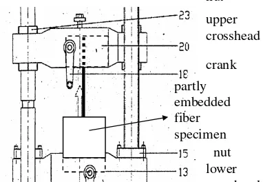
The dimension of specimens is shown by Figure 1 while the setting of pullout test by Figure 3. The pull-out test is provided by computerized Universal Testing Machine “Hung Ta”. The nylon 600 fiber is made in Indonesia with 1.1. mm in diameter and embedded length 150 mm and 180 mm for partly fiber embedded specimens. Mix design for cementitious matrix is cement : sand : water ratio of 1:1:0.6. Analytical method applied by modeling and formulation of theoretical model ([1], [2], [11]). The analytical models are built based on experiment result.
Figure 2 : Setting for pullout test
3. RESULTS AND DISCUSSION
3.1. Results
The results show that nylon 600 fiber has average maximum tension stress of 1471.21 MPa. Figure 3 shows relation of stress-strain of nylon 600 tension test with average maximum strain of 0.89, average maximum elongation of 84.11%, and elongation and the viscosity of nylon itself.
0
Figure 3 : Relation of stress-strain of nylon 600 tension test
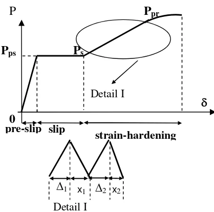
The results of pullout test are shown below. Firstly, the experiment results show that the pullout test represent fracture phenomenon in some stages during pull-out process. Figure 4 describes the stages: (a) Pre-slip stage, (b) Slip stage, and (c) Strain-hardening stage. The pre-slip loads are about 400-430 N and pre-slip displacements are no more than 0.1 mm. The slip
loads are in the same range of pre-slip loads with displacements of 3-4 mm. The strain-hardening loads are observed as 1300-1500 N and its displacement about 150-190 mm.
Figure 4 : The stages during pullout process
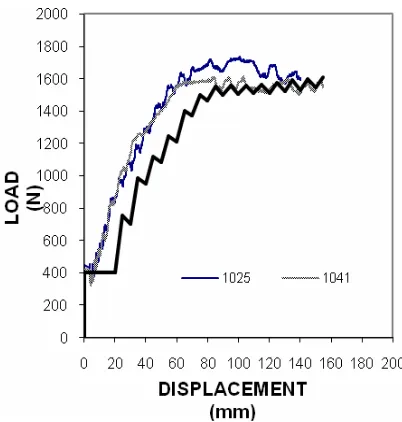
Figure 5 describes relation of load-displacement of specimen with embedded length (lf) of 150 mm
and 180 mm. Specimen 1025 and 1041 have embedded length lf = 150 mm while specimen
2438 has lf = 180 mm. Specimen with lf = 180 mm
has bigger displacement (190.2 mm) than lf = 150
mm (140.08 and 154.76 mm). On the contrary, specimen with lf = 180 mm has lower ultimit load
(1400 N) than lf = 150 mm (1500-1600 N).
Relation of stress-strain of specimen with embedded length (lf) of 150 mm and 180 mm is
described by Figure 6. Specimen with lf = 180 mm
has bigger strain (2.8) compared to lf = 150 mm
(2.06 and 2.28). On the contrary, specimen with lf
= 180 mm has lower ultimit stress (1500 N) than lf = 150 mm (1600-1800 N).
Figure 5 : Relation of load-displacement of specimen with embedded length (lf) of 150 mm
and 180 mm
Figure 6 : Relation of stress-strain of specimen with embedded length (lf) of 150 mm and 180 mm
The results were analyzed to become basis of pullout modeling. Several aspects have been considered in the modeling: (1) Fracture capacity of embedded fiber is a function of Poisson’s ratio of fiber, (2) Some stages exist during the pull-out and fracture pull-out process, (4) A ‘jagged’ phenomenon exists on strain-hardening part of load-displacement (P-) and stress-strain () curves of pull-out, and (4) Unstable and stable
P
P
ps
pre-slip
strain-hardening
P
s0
slip
Detail I
x2 x1
1
2Detail I
fracture process phenomenon exist during the pull-out process.
Pullout modeling conceives a formulation of load which is a function of displacement that is expressed by Equation 1.
Epr = modulus of elasticity at stage of
strain-hardening (MPa)
is specific for every stage (mm) rI = ratio of total free-end fiber
displacement of free-end at stage of pre-slip
rII = ratio of total free-end fiber
displacement of free-end at stage of slip rIII = ratio of total free-end fiber
displacement of free-end at stage of strain-hardening
The range value of Es, Eps, dan Epr for pull-out
model is described by Table 1.
Tabel 1 : Range value of Es, Eps, and Epr stable crack length as expressed by Equation 2.
stable fracture achieved (mm)
= critical fiber strainStable crack length for each embedded length can be calculated based on experiment results as explained by Table 2.
Tabel 2 : Stable Crack Length of Specimens
The pullout model then built based on experiment results and described by Figure 7-10 as follow.
Figure 7 : Relation of stress-strain of experiment results and model with embedded length
lf = 150 mm
Figure 6 and 7 show that the model fit to the experiment results. For relation of load-displacement of experiment results and model with embedded length lf = 150 mm (Figure 6), the
model achieves stage of with load of about 400 N and stage of strain hardening with load of about 1500 N. Figure 7 shows that for stress-strain relation the model achieved stress at stage of slip with load about 400 MPa and stage of strain-hardening with load about 1600 MPa.
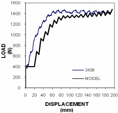
Figure 8 : Relation of load-displacement of experiment results and model with embedded
length lf = 180 mm
Figure 9 : Relation of stress-strain of experiment results and model with embedded length
lf = 180 mm
Figure 8 and 9 also describe that the model fit to experiment results. Figure 8 shows that the model also achieve stage of slip with load of about 400 N and stage of strain-hardening with load of about 1350 N. It is lower than the loads achieved by the specimens with embedded length of lf = 150 mm.
The same phenomenon happened for stress-strain relation of Figure 9. The model achieve stage of slip with load of about 400 MPa and stage of strain-hardening with load of about 1400 MPa. It is lower than the loads achieved by the specimens with embedded length of lf = 150 mm.
3.2. Discussion
It is interesting that the load and stress of embeded length lf = 180 mm are lower compared
to lf = 150 mm. However, the displacement for
embeded length lf = 180 mm is bigger compared
to lf = 150 mm. It can be explained as follow.
The long embedded length (150 mm and 180 mm) produces broken fiber when specimen gets failure. It should be noted that long embedded length of specimen is related to the possibility of crack arrester presence. Because of that bigger possibility makes the strain-hardening part in load-displacement curve is longer for long embedded fiber length. The stable crack length will be achieved in stable fracture.
For both embedded length lf = 150 mm and
lf = 180 mm, the stable crack length are the same,
l2 = 37,7375 mm (Table 2). It can be seen (Figure
7-10) that they achieve same critical load and stress at the stage of slip that the stable fracture occured. Hence, the modeling represents the fracture phenomenon in appropriate way.
4. CONCLUSIONS
The
research meets conclusions:a) Whenever fracture takes place, it is always an unstable crack;
b) Stable cracks are established by the presence of crack arrester;
c) After the establishment of stable cracks, establishment of stable cracks in point g will increase stress (the strain-hardening stage exist), the second slip will not take place;
e) Broken nylon fibers have a longer embedded length because of the possibility of crack arrester presence is bigger than the shorter ones;
f) Since the middle right side of matrix is at the intersection point with fiber acts as crack arrester in the beginning of pull-out process, then the load-displacement (P-) and stress-strain () curves of pull-out test will be the same as the load-displacement (P-) and stress-strain () curves of fiber tension test
ACKNOWLEDGMENT
The author gratefully acknowledges UBCHEA (United Board of Higher Christian Education) for supporting research grant (2005-2007); and to Prof. Ir. Moh. Sahari Besari, MSc., PhD as Promotor; and also to Prof. Bambang Suryoatmono, PhD. as Co-Promotor; for their great contributions of ideas, discussions, and intensive assistance to the dissertation.
.
REFERENCES
[1] Susilorini, Retno, M.I., Model Masalah Cabut-Serat Nylon 600 Tertanam dalam Matriks Sementitis yang Mengalami Fraktur, Dissertation, Unika Parahyangan, Bandung, 2007.
[2] Susilorini, Retno, Rr. M.I., Pemodelan Cabut-Serat Berbasis Fraktur, Unika Soegijapranata Press, 2009.
[3] Susilorini, Retno, Rr. M.I., “Fractured Based Approach for Structural Element Design – Safe
Building, Safe City”, Proceeding Third
International Conference on Economic and Urban Management “City Marketing, Heritage, and Identity”, PMLP Unika Soegijapranata, Semarang, pp. 451-465, 2007.
[4] Susilorini, Retno, Rr. M.I., “Integral-J Kritis untuk Model Elemen Hingga pada Cabut Serat Fraktur Nylon 600”, Tiga Roda Forum “Perkembangan Terkini Teknologi dan Rekayasa Konstruksi Beton di Indonesia”, 12 Desember, Hotel Bumi Karsa - Bidakara, Jakarta, pp. 1-14, 2007.
[5] Susilorini, Retno, Rr. M.I., “Analisa Kegagalan Struktur Berbasis Fraktur untuk Penyelamatan Bumi dan Pembangunan Berkelanjutan”, Makalah, Seminar “Save The Forest, Save The Earth, 5 February, Fakultas Teknik, Unika Soegijapranata, Semarang, pp. 1-11, 2008.
[6] Susilorini, Retno, Rr. M.I., “The Role of Shear-Friction on Pull-Out Fractured Based Modeling of Nylon 600 with Clumped Fiber End”, Seminar Nasional Teknik Sipil IV, 13 Februari, Program Pascasarjana – Jurusan Teknik Sipil, Surabaya, pp. B91-B101.
[8] Susilorini, Retno, Rr. M.I., “A Fractured Based Pull-Out Model of Short Nylon 600 Embedded in Cementitious Matrix”, Jurnal Ilmiah Semesta Teknika (Terakreditasi), Universitas Muhammadiyah Yogyakarta, Vol. 11, No. 1, May, 2008.
[9] Susilorini, Retno, Rr. M.I., “Stable Crack Length on Out Problem – Significant Factor of Pull-Out Modeling for Concrete Pavement Structure’s Element”, Proceeding of International Symposium
XI FSTPT, 29-30 October, Universitas
Diponegoro, pp. 1-9, 2008.
[10]Susilorini, Retno, M.I. Rr, “Striving For ‘Green Concrete’ with Nylon 600 Fiber - A Review of Pull-Out Model with Nylon 600”, Proceeding of Second Annual International Conference Green Technology and Engineering, 15-17 April, Universitas Malahayati, Lampung, pp. 52-56, 2009.
[11]Susilorini, Retno, M.I. Rr, “Model Cabut-Serat Nylon 600 Tertanam dalam Matriks Sementitis Berbasis Fraktur”, Jurnal Dinamika Teknik Sipil
(Terakreditasi), published on Vol. 9 No. 1, July Jurusan Teknik Sipil, Universitas Muhammadyah Surakarta, 2009.
[12]Li, V.C., Chan, Y.W., Wu, H.C., “Interface Strengthening Mechanism in Polymeric Fiber
Reinforced Cementitious Composites”,
Proceedings of International Symposium on Brittle Matrix Composites, (eds. Brandt, A.M, Li, V.C., Marshall, L.H), IKE and Woodhead Publ, Warsaw ,pp. 7-16, 1994.
[13]Clements, M., “Synthetic as Concrete
Reinforcement”, Concrete Magazine, United Kingdom, September, pp. 37-38, 2002.
[14] Martinez-Barrera, G., “Concrete Reinforce with Irradiated Nylon Fibers”, Journal of Material Research, Vol.21, No. 2, February, pp. 484-491, 2006.
[15]Nadai, A., Theory of Flow and Fracture of Solids, Volume I, McGraw-Hill Company. Inc, New York, USA, 1950.
[16]Bazant, ZP., “Fracture Mechanics of Concrete: Concepts, Models, and Determination of Material Properties – State of the Art Report”, Proceedings, First International Conference on Facture Mechanics Concrete Structure (Framcos 1), (Ed. Bazant, ZP), Colorado, USA, pp. 6-140, 1992.