City, Urban, and Heritage 451
E
E
M
M
.
.
1
1
0
0
F
F
R
R
A
A
C
C
T
T
U
U
R
R
E
E
B
B
A
A
S
S
E
E
D
D
A
A
P
P
P
P
R
R
O
O
A
A
C
C
H
H
F
F
O
O
R
R
S
S
T
T
R
R
U
U
C
C
T
T
U
U
R
R
A
A
L
L
E
E
L
L
E
E
M
M
E
E
N
N
T
T
D
D
E
E
S
S
I
I
G
G
N
N
:
:
S
S
A
A
F
F
E
E
B
B
U
U
I
I
L
L
D
D
I
I
N
N
G
G
,
,
S
S
A
A
F
F
E
E
C
C
I
I
T
T
Y
Y
M.I. Retno Susilorini
INTRODUCTION
A modern city grows along the increase of building’s population. Several countries have proved their advanced building development by emphasizing a safe structural design. What is a safe structural design? Answering this question, one approached has been explored since fifty years ago by Bresler and Wollack, 1952, Kaplan, 1961, etc (Bazant, 1992), it is the fracture based approach. In structural engineering field, this approach is a solution to prohibit a catastrophic failure of structure. When a building is constructed, a safe design is the most important requirement to assure the safety criterion.
Some lessons told us about the hazard of structure’s failure that was initiated by cracks and fractures. The fracture of wheels, axles, or rails during 1860-1870 in Great Britain (Broek, 1982), the collapse of Montrose suspension bridge 1830 (Broek, 1982), the failure of Kings Bridge in Melbourne 1962 (Rolfe and Balsom, 1977), the collapse of multi spans of the Schoharie Creek Thruway Bridge 1987 (Li and Wang, 2005), several collapse of structures in Kobe 1994 (Li and Wang, 2005), and also the Mississippi Bridge collapse (Figure 1) on August 2007 that it still debatable (Elswort, 2007). Those accidents experience that a safe design has to cover the possibility of cracks and fractures which may put the structure into
the risk of structure’s failure. Nevertheless, a fracture based design approach can be
implemented by fracture mechanics which is defined as a study of the response and failure of structures as a consequence of crack initiation and propagation (Shah, et. al, 1995). The fracture mechanics provides failure theory which uses energy criterion and take into account the failure propagation (Bazant, 1992).
City, Urban, and Heritage 452 It is clear that concrete structures are the most popular type of building structure. The concrete structures combined with steel, timber, fiber, or other materials. Those materials, some times, behave unsatisfactorily because of the brittleness of concrete. According to Bazant (1992), it is understood that the failure of concrete structures should consider the strain-softening related to distributed cracking, localized crack that grows to larger fracture prior to failure, and bridging stresses at the fracture front. Therefore, the suppression of fracture of concrete can be implemented by improving higher toughness and higher tensile ductility (Li and Wang, 2005). The need of better performance is fulfilled by the birth of several types of material (Fischer and Li, 2004) such as Fiber Reinforced Concrete (FRC), High Performance Fiber Reinforced Cementitious Composites (HPRFCC) which is known as Engineered Cementitious Composites (ECC). Without neglecting the conventional design of concrete structures, the fracture based approach then being introduced by fracture mechanics into the concrete design. The fracture based design that is implemented by fracture mechanics will meet failure criterion of concrete structure. By using fracture mechanics, the design is going to achieve a more safety margin for structure that improves economic value as well as structural benefit.
A safe design of building means a proper-accurate design of structural elements of the building itself. The conventional design of concrete and reinforced concrete (as well as FRC, HPRFCC, and ECC) is based on the ultimate-limit analysis and service performance analysis that uses strength-based failure criterion for determining the loading capacity of the structures. For fracture based design context, the ultimate-limit analysis calculates loading behavior of structure by combining stress equilibrium, strain compatibility, and constitutive laws of materials at failure (Shah,et.al, 1995). Obviously, fracture mechanics gives solution to answer the demand of safe building by considering fracture phenomenon at all structural elements.
City, Urban, and Heritage 453 There is no doubt that fracture mechanics is very important for fiber cementitious composites. The improvement of fiber cementitious composites such as FRC, HPRFCC, and ECC is engaged to the fiber application such as nylon, which is categorized as synthetic fiber. It should be noted that fiber takes an important role in determining whole fiber-reinforced cementitious composite (FRC) performance. For certain reasons, nylon fibers in cementitious composites will improve strain-hardening property (Susilorini, 2007), tension strength, elastic modulus. Previous researches have proved a better performance of ECC using various synthetic fiber surfaces (Li, Chan, and Wu, 1994), high performance as alike steel performance (Clements, 2002), and even higher compressive stress for irradiated nylon fiber by gamma (Martinez-Barera, 2006). The nylon fiber has a special characteristic of
multiple constrictions at stretching condition (Nadai, 1950) called ‘yield point elongation’ that
has magnitude of 200%-300% of initial fiber length. Because of the nylon viscosity, the load may gradually decrease while the fiber length becomes longer two or three times. The
multiple constrictions of nylon fiber appeared by ‘jagged’ phenomenon of stress-strain or load-displacement curves (Avarett, 2004; Susilorini, 2007).
When a safety margin becomes a significant factor of design, then a safe building is a must. This paper want to address the importance of fracture based approach for structural
elements design to achieve ‘safe building, safe city’ by showing the experimental result and
modelling of fracture pull-out of Nylon 600 which used J-Integral as fracture parameter.
RESEARCH METHODS
The research aims to implement fracture based approach of fracture pull-out of Nylon 600 by experimental method and analytical method. Both methods will be explained below.
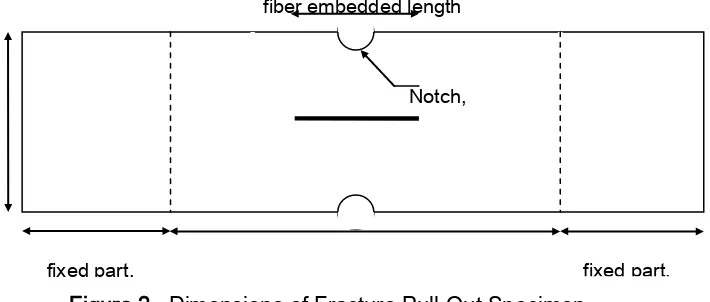
Figure 2. Dimensions of Fracture Pull-Out Specimen
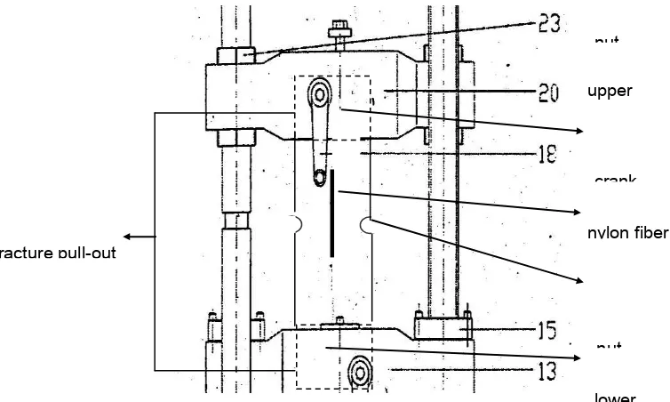
The experiment method applied pull-out test with specimen’s dimension described by Figure 2 and set up of the pull-out test by Figure 3. The pull-out test conducted by computerized
fixed part,
Notch, fiber embedded length
City, Urban, and Heritage 454
Universal Testing Machine “Hung Ta”. This research used nylon 600 fiber of local made
(“Golden Fish” brand, made in Indonesia) with 1.1. mm in diameter and embedded length
100 mm. Mix design for cementitious matrix is cement : sand : water ratio of 1:1:0.6. Analytical method firstly applied by modelling and formulation of theoretical model (Susilorini, 2007). Secondly, the analytical method is followed by calculation of J-Integral as fracture criterion that applied to experimental result and model. The calculation of J-Integral of model will be compared to the experimental results.
Figure 3. The pull-out test for fracture pull-out specimen
RESULTS OF THE STUDY
1. Experimental Results
The experimental results that all the fracture pull-out specimens with embedded fiber length lf
= 100 mm meet fibers broken. The relation of load-displacement (P-) is described by Figure 4. The curves of Figure 4 have shown several stages of the whole fracture pull-out process, they are: (a) Stage of pre-slip, (b) Stage of slip, (c) Stage of transition, and (d) Stage of strain-hardening with ‘jagged’ phenomenon. The load at stage of pre-slip found as 1200-3000 N with displacement of no more than 1 mm. At stage of slip, the load is about 10-300 N with displacement of 1-1.75 mm. The stage of transition shows the load of 10-50 N with displacement of 1.75-25 mm. For stage of strain-hardening, the load ranged about 300-1000 N with displacement at the time of fiber broken ranged about 58-60 mm.
nylon fiber upper
lower nut crank
fracture pull-out
City, Urban, and Heritage 455
0 200 400 600 800 1000 1200 1400
0 10 20 30 40 50 60 DISPLACEMENT
(mm)
LO
AD (N)
706
730
Figure 4. The load-displacement (P-) relation of fracture pull-out specimen with lf = 100 mm
2. Fracture Pull-Out Modelling
The fracture pull-out model shall be constructed to represent the fracture phenomenon happening during the pull-out process. Several aspects were considered to get comprehensive fracture pull-out model, they are: (1) Fracture capacity of embedded fiber is a
function of Poisson’s ratio of fiber, (2) Some stages exist during the fracture pull-out process,
(4) A ‘jagged’ phenomenon exists on strain-hardening part of load-displacement (P-) and stress-strain () curves of pull-out, and (4) Unstable and stable fracture process phenomenon exist during the fracture pull-out process.
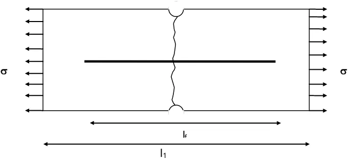
Figure 5. Fracture pull-out specimen at instantaneous normal crack and lateral crack
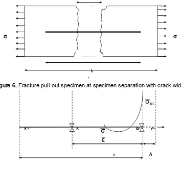
The fracture process happened on fracture pull-out problem is similar to the pull-out problem one (Susilorini, 2007). During the elastic stage, the fiber is fully embedded in cementitious matrix. At the initial stage of fracture process (Figure 5), the normal crack and lateral crack exist instantaneously, and the unstable fracture process being established (Figure 6). When the unstable fracture process becomes stable, the specimen is separated with crack width of c (Figure 6). At this time, the displacement applied at the outer side of separated specimen.
lf
City, Urban, and Heritage 456 Figure 6. Fracture pull-out specimen at specimen separation with crack width c
Figure 7. Fracture pull-out model at elastic stage
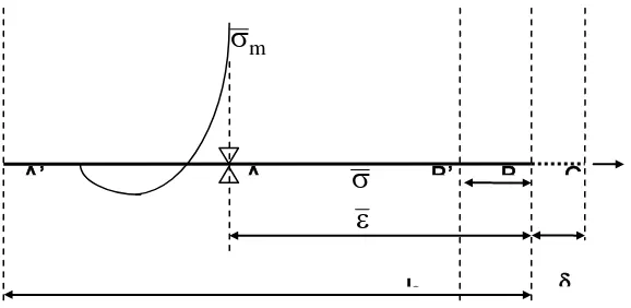
Figure 7 shows a half part of embedded fiber (A’B) with embedded fiber end at A’ which is constrained at A and B. Free part of fiber at C is belong to the other part of specimen. Embedded fiber end called lf. A displacement is applied at C and both cementitious matrix
and fiber are still in composites condition. The displacement will generate matrix stress m.
The value of matrix stressm increases until
m
m
m
.The value of critical matrixstress
m is a bond capacity at the time of crack which represents the ultimate fracture tension capacity. Thus, the strain and stress at BC will be:0 1
l
(1)
s 1 1
E
(2)During the elastic stage, displacement keeps growing, and then a crack will be formed. This crack emerges unstable fracture process. Because of the existence of crack, unstable fracture process phenomenon will release the constraint at B (Figure 8). The crack length is growing to be as long as l2. When unstable fracture process is established, the constraint at A
A B
l2
0.5 l
m
A’ C
lf
City, Urban, and Heritage 457 still can remove to left side. When the crack length l2 is longer than embedded length lf, the
fiber may be pulled-out.
Figure 8. Fracture pull-out model at unstable fracture process
Figure 9. Fracture pull-out model at stable fracture process
The unstable fracture process will change into a stable fracture process. Assume that a crack firstly formed as x (Figure 9), then the increasing of displacement will also increase strain
1 and stress 1 at B’B. Those strain 1 and stress 1 increasing will reach critical value of
matrix stress
m and strain. When the displacement repeated at B’, then another new crack x will form at the left side of fiber. It happened continuously until constraint A is fixed. The constraint A becomes crack arrester which prevents crack growing. In this situation the crack will be stopped to grow and crack length remains l2. Once stable crack length l2achieved, then strain at l0 part transfer to l2 part. The stress and strain become:
City, Urban, and Heritage 458 Whenever the condition of
m
m
is achieved and strain at AC becomes . Hence,
and the strain expressed by:
2
Thus, the stable crack is formulated as:
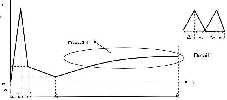
The model is formulated by equation (9) and result a P- (load-displacement) curve (Figure 10) that consists of 4 (three) stages: (a) Stage of pre-slip, (2) Stage of slip, (3) Stage of transition, and (4) Stage of strain-hardening. During the stage of pre-slip, the fiber is fully embedded in cementitious matrix. The fracture process phenomenon has not already happened yet. After critical matrix stress
m exceeded, a crack is formed. At this time, the stage of slip and unstable fracture process begin. The normal fracture that is happened between the two notches generates and followed by lateral fracture after the separation of specimen. These normal and lateral fractures happen instantaneously. The unstable fracture process may change into stable fracture process when the stable crack length reached at the end of slip stage or transition stage. The stable fracture process will initiate the stage of strain-hardening with ‘jagged’ phenomenon. During the stage of strain-hardening, the increase of strain
will increase the stressalong the fiber until the fiber gets broken.Figure 10. The load-displacement (P-) relation of fracture pull-out process
City, Urban, and Heritage 459 The values of Es, Eps, Etr, and Epr, in equation (9) are based on experimental result (Table 1).
Table 1.
Value of Es, Eps, Etr, and Epr for Fracture Pull-Out Model
STAGE OF STAGE OF SLIP STAGE OF STAGE OF
PRE-SLIP INITIAL OF SLIP END OF SLIP TRANSITION STRAIN-HARDENING
Eps Es Es Etr = En Epr = En
(MPa) (MPa) (MPa) (MPa) (MPa)
100000 -
150000 100000 - 150000 4000 -5000 40 - 60 100 - 700
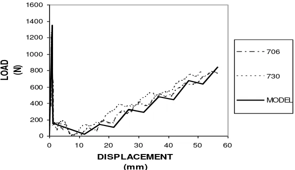
The P- (load-displacement) curves of model and experimental results described by Figure 11 while for the fiber stress-displacement (-) one described by Figure 12.
0
Figure 11. The load-displacement (P-) relation of model and experimental results for fracture pull-out specimen with lf = 100 mm
0
City, Urban, and Heritage 460 3. J-Integral
The J-Integral is a fracture parameter of fiber cementitious composites with strain-hardening behaviour. It should be emphasized that the J-Integral functions as fracture characterization of non-linear fracture mechanics analysis to represent strain energy released rate (Kabele dan Li, 1998). In this case, the crack driving force of non-linear material is defined as the path-independent of J-Integral. The research improves the Marshall and Cox (1988) equation (10) for crack tip toughness based on J-Integral analysis due to steady-state crack propagation (Figure 13). The steady-state cracking stress ss can be described as the stress
at time of bridging stress increase to the magnitude of applied load while the crack flatten to maintain the constant applied stress level (Li and Wu, 1992). The steady-state cracking stress ss must be lower than maximum bridging stress 0.
Figure 13. The concept of fiber bridging complementer energy (Li, 2000) on the equation (10) is defined by equation 11-14:
City, Urban, and Heritage 461
Total J-Integral then formulated as follows:
pr show the J-Integral of model and experimental results for each stage described by below.
Table 2.
The J-Integral for each stage of model and experimental results
J-INTEGRAL J-INTEGRAL J-INTEGRAL J-INTEGRAL J-INTEGRAL
lf = 100 PRE-SLIP SLIP TRANSITION STRAIN-HARDENING TOTAL
(mm) (N/mm) (N/mm) (N/mm) (N/mm) (N/mm)
MODEL 1287.388 428.834 942.503 18568.000 21226.725
706 674.723 164.143 553.169 27877.099 29269.134
730 146.436 139.79 793.269 18364.693 19444.188
0
Figure 14. The J-Integral of model and experimental results
DISCUSSION AND CONCLUSIONS
1. Discussion
City, Urban, and Heritage 462 case tr) must be lower than maximum bridging stress 0 (in this case pr). The condition
shows the transition of stage of transition to stage of strain-hardening and emphasizes the importance of total complementary energy (see Figure 10) in fiber cementitious composite design.
The total J-Integral value of model fit to total J-Integral value of experimental results, about 19000-30000 N/mm (Table 2 and Figure 14). Thus, the model of fracture pull-out represents the fracture phenomenon properly. The crack arrester will be established at the end of stage of slip, thus the strain energy released rate that is implemented by J-Integral will increase at the stage of transition, and achieves the maximum value at the stage of strain-hardening. Therefore, the increase of strain after the establishment of stable cracks may increase stress and definitely the second slip will not take place. Obviously, this fracture based approach cannot be found at conventional structural element design.
2. Conclusions
Several theories have been established by this research:
a) The fracture characterization of fiber cementitious composites determines the J-Integral as strain energy released rate
(b) The J-Integral of each stage gives contribution to the total J-Integral during the fracture pull-out process
(c) The increase of steady-state cracking stress tr to maximum bridging stress pr shows the
transition of stage of transition to stage of strain-hardening and emphasizes the importance of total complementary energy in fiber cementitious composite design
(d) The model of fracture pull-out represents the fracture phenomenon properly
(e) Several new equations derived to calculate J-Integral for each stage during fracture pull-out process which is based on the equation of Marshall and Cox (1988)
(f) The crack arrester will be established at the end of stage of slip; therefore the strain energy released rate that is implemented by J-Integral will increase at the stage of transition and reaches the maximum value at the stage of strain-hardening
ACKNOWLEDGMENTS
City, Urban, and Heritage 463
NOTATION
A fiber section area (mm2)
Afl fiber surface area (mm2)
Am matrix surface area (mm2)
c crack width (mm) D fiber diameter (mm)
En, Epr modulus of elasticity at stage of strain-hardening (MPa)
Eps modulus of elasticity at stage of pre-slip (MPa)
Es modulus of elasticity at stage of slip (MPa)
P, Pn tension load (N)
a1 total displacement of a stage (mm)
a2 initial length of specimen or fiber that is specific for every stage (mm)
b specimen width (mm) Jtip crack tip toughness (N/mm)
Jps J-Integral for stage of pre-slip (N/mm)
Js J-Integral for stage of slip (N/mm)
Jtr J-Integral for stage of transition (N/mm)
Jpr J-Integral for stage of strain-hardening (N/mm)
l0 initial outer fiber length (mm)
l2 stable crack length (mm)
lf embedded fiber length (mm)
lsf length of shear-friction (mm)
rI ratio of total free-end fiber displacement of free-end at stage of pre-slip
rII ratio of total free-end fiber displacement of free-end at stage of slip
rIII ratio of total free-end fiber displacement of free-end at stage of strain-hardening
xi relaxation length for n at stage of strain-hardening (mm)
0 maximum bridging displacement (MPa)
ss displacement at steady-state cracking stress (mm)
ps displacement at stage of pre-slip (mm)
s displacement at stage of slip (mm)
tr displacement at stage of transition (mm)
pr displacement at stage of strain-hardening (mm)
i free-end displacement for n at stage of strain-hardening (mm)
0 maximum bridging stress (MPa)
1 fiber stressat the midldle of right side of matrix (MPa)
2
l
City, Urban, and Heritage 464
ss steady-state cracking stress (MPa)
ps fiber stress at stage of pre-slip (MPa)
s fiber stress at stage of slip (MPa)
tr fiber stress at stage of transition (MPa)
pr fiber stress at stage of strain-hardening (MPa)
REFERENCES
Avarett, RD (2004). “Fracture Mechanics of High Performance Nylon Fibers”, Thesis, Georgia Institute of Technology, USA.
Bazant, ZP. (1992). “Fracture Mechanics of Concrete: Concepts, Models, and Determination of Material Properties – State of the Art Report”, Proceedings, First International Conference on Facture Mechanics Concrete Structure (Framcos 1), (Ed. Bazant, ZP), Colorado, USA, pp.6-140.
Broek, D. (1982). “Elementary Engineering Fracture Mechanics”, Martinus Nijhoff Publishers, The Hague, Boston, London.
Clements, M. (2002). “Synthetic as Concrete Reinforcement”, Concrete Magazine, United
Kingdom, September, 37-38.
Elsworth, C. (2007). “Mississippi Bridge Collapse Survivors Speak”, Telegraph co.uk, taken
August 5 from www.telegraph.co.uk.
Fischer, G., Li, V.C. (2004). “Effect of Fiber Reinforcement on the Response of Structural Members”, Proceedings Framcos-5, (eds. Li, et. al). Ia-Framcos, 831-838.
Kabele, P., Li, V.C. (1998). “Fracture Energy of Strain-Hardening Cementitious Composites”,
Proceedings, Framcos-3, AEDIFICATIO Publishers, Freiburg, Germany, 487-498.
Karihaloo, BL. (1995). “Fracture Mechanics and Structural Concrete”, Longman Scientific & Technical, Essex, England.
Li, V.C. (2000). “J-Integral Applications to Characterization and Tailoring of Cementitious Material”, Multiscale Deformation and Fracture in Materials and Structures, T.J. Chuang dan J.W. Rudnick (eds), Kluwer Academic Publishers, Netherlands, 385-406.
City, Urban, and Heritage 465
Li, V.C., Wu, H.C. (1992). “Conditions for Pseudo Strain-Hardening in Fiber Reinforced
Brittle Matrix Composites”, Applied Mechanics Rev. on “Micromechanical Modelling of Quasi-Brittle Materials Behavior”, (ed. Li, V.C.), ASME, Vol. 45, No. 8, August, 390-398.
Li, V.C., and Wang, S. (2005). “Suppression of Fracture Failure of Structures by Composite Design based on Fracture Mechanics”, corresponding paper in Compendium of Papers CD ROM, Paper 5543.
Li, V.C., Chan, Y.W., Wu, H.C. (1994). “Interface Strengthening Mechanism in Polymeric
Fiber Reinforced Cementitious Composites”, Proceedings of International Symposium on Brittle Matrix Composites, (eds. Brandt, A.M, Li, V.C., Marshall, L.H), IKE and Woodhead Publ, Warsaw, 7-16.
Marshall, D.B., Cox, B.N. (1988). “A J-Integral Method for Calculating Steady-State Matrix Cracking Stresses in Composites”, Mechanics of Material, Vol. 7, pp. 127-133.
Martinez-Barrera, G. (2006). “Concrete Reinforce with Irradiated Nylon Fibers”, Journal of Material Research, Vol.21, No. 2, February, pp. 484-491.
Nadai, A. (1950). “Theory of Flow and Fracture of Solids”, Volume I, McGraw-Hill Company. Inc, New York, USA.
Rice, J.R. (1968). “Mathematical Analysis in the Mechanics of Fracture”, in Fracture: An Advanced Treatise, Vol. II, ed. Liebowits, H., Academic, New York, pp. 191-311.
Rolf, ST, and Barsom, JM. (1977). “Fracture and Fatique Control in Structure – Applications
of Fracture Mechanics”, Prentice-Hall Inc., New Jersey.
Shah, S.P., Swartz, S.E., Ouyang, C. (1995). “Fracture Mechanics of Concrete: Applications
of Fracture Mechanics to Concrete, Rock, and Other Quasi-Brittle Materials”, John Wiley & Sons, Inc., New York.
Susilorini, R. (2007). “Model Masalah Cabut-Serat Nylon 600 Tertanam dalam Matriks
Sementitis yang Mengalami Fraktur”, Dissertation, Parahyangan Catholic University, Bandung.

