UDK 621 Pregledni članak
Prihvaćeno za tisak: 12. svibnja 2012.
BENDING STIFFNESS OF ALUMINIUM FOAMS
Tomislav Filetin Summary
The basic manufacturing processes of cellular materials have been briefly noted as well as the metal foam properties. The most widely used are the aluminium foams due to the following properties: very good insulation (ther-mal insulation and sound absorption), low density (mass), high specific rigi -dity in sandwich structures, very good impact damping, corrosion resistance, non-flammability, very good recyclability, etc. Almost the all properties are basically determined by the type of cells (closed or open), their size and dis-tribution i.e. relative density.
This article focuses on the testing and determining the bending stiffne -ss for different foamed cro-ss section shapes, which are very important for analysis of behaviour of the lightweight stiff construction elements. The ro -und, quadratic, hexagonal and I-shapes have been made by powder metallur-gical Foaminal-Alulight process. These shapes have been foamed from alloy AlSi10 precursor with foaming agent TiH2 having density of 1000 kg/m3 and all of the profiles have had the same cross section area and volume. The four-point bending test was applied. From the load-deflection diagram the bending stiffness (EI) has been calculated for each cross section shape. I-shaped profile has the highest bending stiffness comparing to the other shapes, which is in good correlation with bending stiffness of such solid shapes. The common relation between bending stiffness of foamed and solid shape, which include relative density, has been proposed.
Keywords: aluminium foams; mechanical properties; bending stiffness
1 INTRODUCTION
Metal foams represent a more recent form of cellular metal materials structu-re (40 % to 90 % porosity), which tend to imitate the structustructu-re of natural materials – wood, bone, cork, coral (Figure 1). Cellular structures permit an optimisation of strength or stiffness, energy absorption by low weight of material, heat isolation or heat exchange. For example, the polymeric and ceramic foams are widely used for isolations elements, filters, or in packaging. However they can’t be used for structural purposes, due to insufficient rigidity of the polymers or brittleness of ceramics.
Rad 513. Tehničke znanosti knj. 15 (2012), str. 93-116
94
The cells may be closed or open, non-uniformly (random) distributed or spa-tially ordered (oriented). It is the structure of the metal foams which influences most their properties.
The oldest known artificial foam – namely polymeric foams generally have a regular microstructure, whereas metallic foams are highly disordered with wide dispersion of cell size and cell shape. Moreover, many imperfections exist in this structure, such as cracks or holes in the walls, corrugated cells etc.
Today, the tendency is to influence the structure by adjusting the parameters during the production itself, thus influencing also the properties of this type of material.
Metal foams are most commonly produced on the basis of aluminium (Al) and nickel (Ni) – mainly open cells. Also available are foams based on titanium (Ti), magnesium (Mg), lead (Pb), copper (Cu), zinc (Zn), bronze, steel.
Fig. 1. Natural cellular materials: (a) cork, (b) balsa, (c) sponge, (d) trabecular bone, (e), coral (f), cuttlefish bone, (g) Iris leaf, (h) plant stalk [1], (i) aluminium foam closed cell structure, j) open cells metal foams [2]
Sl. 1. Prirodni ćelijasti materijali: (a) pluto, (b) balza, (c) spužva, (d) kost, (e), koralj (f), riblja kost, (g) list irisa, (h) stabljika biljke [1], (i) građa aluminijske pjene sa zatvorenim ćelijama, j) otvorene ćelije metalne pjene [2]
2
i) j)
Fig. 1. Natural cellular materials: (a) cork, (b) balsa, (c) sponge, (d) trabecular bone, (e), coral (f), cuttlefish bone, (g) Iris leaf, (h) plant stalk [1], (i) aluminium foam closed cell structure, j) open cells metal foams [2]
Sl. 1. Prirodni ćelijasti materijali: (a) pluto, (b) balza, (c) spužva, (d) kost, (e), koralj (f), riblja kost, (g) list irisa, (h) stabljika biljke [1], (i) građa aluminijske pjene sa zatvorenim ćelijama, j) otvorene ćelije metalne pjene [2]
i) j)
Fig. 1. Natural cellular materials: (a) cork, (b) balsa, (c) sponge, (d) trabecular bone, (e), coral (f), cuttlefish bone, (g) Iris leaf, (h) plant stalk [1], (i) aluminium foam closed cell structure, j) open cells metal foams [2]
Sl. 1. Prirodni ćelijasti materijali: (a) pluto, (b) balza, (c) spužva, (d) kost, (e), koralj (f),
riblja kost, (g) list irisa, (h) stabljika biljke [1], (i) građa aluminijske pjene sa
zatvorenim ćelijama, j) otvorene ćelije metalne pjene [2]
2
i) j)
Fig. 1. Natural cellular materials: (a) cork, (b) balsa, (c) sponge, (d) trabecular bone, (e), coral (f), cuttlefish bone, (g) Iris leaf, (h) plant stalk [1], (i) aluminium foam closed cell structure, j) open cells metal foams [2]
Sl. 1. Prirodni ćelijasti materijali: (a) pluto, (b) balza, (c) spužva, (d) kost, (e), koralj (f),
riblja kost, (g) list irisa, (h) stabljika biljke [1], (i) građa aluminijske pjene sa
2 METAL fOAMING TECHNOLOGIES
The cellular structure is primary the result of the processing methods, which can be classified according to Figure 2.
Fig. 2. Overview of the different ways of processing cellular metals [2] Sl. 2. Pregled različitih mogućnosti za proizvodnju ćelijastih materijala [2]
When comparing cellular metals, the following criteria should be taken into consideration [2]:
– the metal condition during production of porosity: liquid, solution or emulsion, solid;
– the forming process involved: casting, foaming, deposition, sintering; – the method of pore formation: incorporating hollow substrates,
remova-ble substrates, or gas.
There are nine known methods of producing metal foams, particularly alu-minium, today, and six of them are in commercial use:
A. Melt foaming:
– by injecting gas into the melt (commercial name: CYMAT, HKB process); – by dissolving foaming agent – TiH2 (commercial name: ALPORAS,
COM-BAL);
B. Foaming of precursor generated by powder compression – powder me -tallurgy processes:
– dissolving of foaming agent in compressed powder (commercial name: ALULIGHT, FOAMINAL, AFS);
– expansion of gas contained in hot isostatically compressed powder mixture (commercial name: LDC);
– gas is generated during reactive powder sintering.
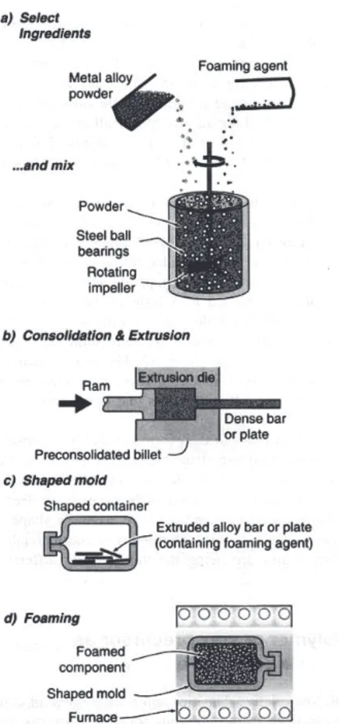
Powder metallurgic processes are among the most highly developed metal foaming methods, since they have some decisive advantages over the other pro-cess chains. The most widened manufacturing propro-cess for aluminium foams is dissolving of foaming agent in compressed powder (Figure 3).
Fig. 3. The sequence of PM steps used to manufacture metals foam by gas-releasing particles in semi-solids (The Fraunhofer and the ALULIGHT processes)
Sl. 3. Slijed faza procesa metalurgije praha (PM) za izradu metalnih pjena plinom oslobođenih čestica u polučvrstom stanju (Fraunhofer i ALULIGHT proces)
The powder of pure metal or alloy is mixed with powder TiH2 (Figure 3). Then, the mixture is compressed into the semi-product (precursor) in the form of a beam or panel. The semi-product in the form of small pieces is distributed uniformly into the mould and heated to a temperature slightly higher than the solidus. This results in the decomposition of TiH2 and creation of highly porous material. After melting and releasing a gas from the precursor (forming the po -res) mould is rapidly cooled to prevent collapse of the foamed structure.
The main advantage of the powder metallurgical process is the possibility to use a precursor prepared by compacting of powdered metal or alloy which contains powdered foaming agent extruded in simple form – wire, granulate, rod etc. Diverse aluminium parts can be foamed in mould – panels, profiles or more complicated 3D shapes, as well as integral structural parts such as sandwiches or hollow profiles filled with foam. The foamed parts usually have a dense surface skin, which significantly improves bending stiffness and surface roughness.
3 PROPERTIES Of METAL fOAMS
The properties of metal foams are basically determined by their structure, chemical composition and the methods of production and treatment.
The parameters that influence the structure-sensitive properties of cellular metals are (ordered by their importance) [2]:
– properties of cell wall material,
– relative density – relation between the foam density and density of the cell wall material,
– type of cellular structure (open or closed cells),
– the fraction of the solid contained in the cell nodes, edges or the cell faces (for a closed cell),
– irregularity of gradients in mass distribution, – the cell size and size distribution,
– shape of the cells and the anisotrophy of cells, – connectivity of cell edges,
– defects, by which we mean buckled or broken cell walls.
Almost all mechanical and physical properties depend basically on the rela-tive density r/rS (or porosity) non-linearly [3]:
where: k, a – constants, P – property of foam,
Ps – property of the cell wall material, r – foam density,
rs – density of the cell wall material.
The basic properties and advantages compared to other materials are: – very low mass (density ranging from 250 to 900 kg/m3 ) – e.g. floats on wa
-ter,
– very good impact absorption capacity, – good vibrations damping capacity, – very good sound absorption capacity,
– flame-retardant property and non-flammability,
– low thermal conductivity (closed cells) – thermal insulators
– high thermal conductivity (open cells) – thermal conductors (especially nickel ones),
– very high specific stiffness (ratio of the modulus of elasticity and density) in sandwich structures,
– corrosion resistance (especially the aluminium, titanium, nickel ones), – recycling possibility (especially aluminium ones).
It is considered that at least four of the listed desirable properties (advan-tages) have to be met for optimal application of the metal foam with closed cells compared to other materials.
This work describes briefly only some of the mechanical properties of metal foams, whereas more detailed descriptions can be found in literature, especially in [2, 3, 4, 17, 18, 19, 20, 23, 24].
3.1 Mechanical properties of metal foams
From a number of necessary properties in the application, special importance lies in the behaviour of the foams in compression static load, rather than the ten-sile load. Open-cell foams have very well defined plateau stress (Ret) presented in Figure 4. In this kind of stress the cells start to flow due to bending. Closed cells foams feature a much more complex behaviour, but they have the same form of curve. The stress of the plateau stress value causes cell collapse (cell walls buckle) and finally there is a region of densification as the cells walls crush to -gether which result with the final densification strain (eD).
ε, % ε, % σ , M Pa , , ρ ρ/ s=0,12 ρ ρ/ s=0,12 Longitudinal Transverse Longitudinal Transverse σ , M Pa ∼Ret ∼Ret
Fig. 4. Compression curves for two types of aluminium foams [2] Sl. 4. Krivulje stlačivanja za dvije vrste aluminijskih pjena [2]
Impact loading is a special case of dynamic compression behaviour. Very good impact absorption is one of the most interesting application properties of foams. There is special interest expressed by the transportation means industry in the manufacture of vehicle parts that are exposed to impact loads in service (e.g. bumpers, engine struts, etc.). This property is also important in the packa-ging materials that may be exposed to impacts during transportation.
Good insight into the capability of impact absorption is given in the diagram
loading – compression deformation in compression loading (Figure 4). Regarding
this property it is important for the area below the curve to be as large as possible – which means maximally high plateau stress Ret, at the same time with maxi-mum densification strain eD. The optimal impact absorption can be adjusted by
changing the foam density. The energy absorption of impact per unit of volume (Wv) is presented by the relation (2) from [3].
Empirical relations between the plateau stress, densification strain and rela -tive density according to [3] are expressed in the form of:
where: Re – yield strength of the foam walls material, m – exponent which ranges for metal foams from 1.5 to 2.0, and coefficient a1 from 1.4 to 2.0.
At tensile load the strain continually increase with the increasing of stress
(Fig. 5). Tensile behaviour has not a great importance in real applications, only for analysis and the design of sandwich bending loaded structures, especially for panels.
Fig. 5. Tensile stress-strain curves for three types of aluminium foams [11] Sl. 5. Krivulje naprezanje-istezanje za tri vrste aluminijskih pjena [11]
Mechanical properties of commercially available metal foams are presented in Tabl. 1.
Table 2 presents theoretical expressions for calculating the mechanical pro-perties of metal foams. These expressions clearly indicate that the mechanical properties are mostly influenced by relative density r/rS.
Table 1- Mechanical properties of metal foams [3] Tablica 1- Mehanička svojstva metalnih pjena [3]
Mechanical properties
Commercial type of foam and material CYMAT Al-SiC ALULIGHT Al ALPORAS Al ERG Al INCO Ni Relative density, r/rS 0.02-0.2 0.1-0.35 0.08-0.1 0.05-0.1 0.03-0.04
Structure closed cells open cells
Density, r, Mg/m3 0.07-0.56 0.3-1.0 0.2-0.25 0.16-0.25 0.26-0.37
Modulus of elasticity, E, GPa 0.02-2.0 1.7-12 0.4-1.0 0.06-0.3 0.4-1.0
Shear modulus, G, GPa 0.001-1.0 0.6-5.2 0.3-0.35 0.02.0.1 0.17-0.37
Flexural modulus, E, GPa 0.03-3,3 1.7-12 0.9-1.2 0.06-0.3 0.4-1.0
Poisson ratio, υ 0.31-0.34 0.31-0.34 0.31-0.34 0.31-0.34 0.31-0.34
Compression strength, Rmt, MPa 0.04-7.0 1.9-14 1.3-1.7 0.9-3.0 0.6-1.1
Yield strength, Re, MPa 0.04-7.0 2.0-20 1.6-1.8 0.9-2.7 0.6-1.1
Tensile strength, Rm , MPa 0.05-8.5 2.2-30 1.6-1.9 1.9-3.5 1.0-2.4
Endurance limit, Rd, MPa 0.02-3.6 0.95-13 0.9-1.0 0.45-1.5 0.3-0.6
Densification strain, ƐD 0.6-0.9 0.4-0.8 0.7-0.82 0.8-0.9 0.9-0.94
Tensile ductility, Ɛf 0.01-0.02 0.002-0.04 0.01-0.06 0.1-0.2 0.03-0.1
Loss coefficient, η, % 0.4-1.2 0.3-0.5 0.9-1.0 0.3-0.5 1.0-2.0
Hardness, H, MPa 0.05-10 2.4-35 2.0-22 2.0-3.5 0.6-1.0
Fracture toughness, KICC, MPam1/2 0.03-0.5 0.3-1.6 0.1-0.9 0.1-0.28 0.6-1.0
Table 2 - Expressions used to calculate the mechanical properties of metal foams [3] Tablica 2 - Izrazi za proračun mehaničkih svojstava metalnih pjena [3]
Mechanical properties open cells closed cells
Modulus of elasticity, E , GPa E = (0.1-4)Es(r/rs)2 E = (0.1-1)Es⋅ (0.5(r/rs)2+0.3(r/rs))
Shear modulus, G , GPa G ≈ 3/8E
Volume modulus, K , GPa K ≈ 1.1E
Flexural modulus, Ef , GPa Ef ≈ E
Poisson ratio, υ 0.32-0.34
Compression strength, Rmt , MPa Rmt = (0.1-1)Rmt,s (r/rs)3/2 Rmt=(0.1-1)Rmt,s×(0.5(r/rs)2/3+0.3(r/rs)) Tensile strength, Rm , MPa Rm ≈ (1.1-1.4)Rmt
Endurance limit, Rd , MPa Rd ≈ (0.5-0.75)Rmt
Densification strain, ƐD eD= (0.91)⋅(1.4r/rs+0.4(r/rs)3) eD = (0.9-1)⋅(1-1.4r/rs+0.4(r/rs)3)
Loss coefficient, η η≈ (0.95-1.05)⋅ηs/(r/rs) Hardness, H, MPa H = Rmt(1+2r/rs)
Specific strength (ratio of strength and density) of aluminium foams (ratio of yield strength and density) is especially favourable, compared to steel, alumini-um and magnesialumini-um, in bending loaded panels (Figure 6).
Steel Al-alloys Mg-alloys AlSi12 foam
C ha ng e of p ar am et er , R , % Parameter, :R Re/ρ tension/compresion Re /ρ3/2 bending of beams Re /ρ2 bending of plates Steel Al-alloys Mg-alloys AlSi12 foam ρ, gcm-3 E, GPa 7,8 350 2,7 210 1,8 160 0,5 12
Fig. 6. Parameter R – ratio of strength and density, for different materials and loading conditions (Re – yield strength of material, r - density, value of steel: 100 %) [4]
Sl. 6. Parametar R – omjer čvrstoće i gustoće, za različite materijale i uvjete opterećenja (Re – granica tečenja materijala, r – gustoća, vrijednost za čelik: 100 %) [4]
Modulus of elasticity
The modulus of elasticity depends strongly on foam density (Fig. 7). Accord-ing to the results of testAccord-ing by vibration methods [5, 8] the dependence obys a power-law with the exponent of about 1.6:
(5)
Fig. 7. Power-law dependence between density and modulus of elasticity for aluminium foam [5] (left), [8] (right)
The dissipation of the values for modulus of elasticity, visible in Fig. 8, is affected by manufacturing methods, type of cells (open or closed) and testing methods (compression or tension).
Fig. 8. Elasticity modulus vs. aluminium foam density [13]
Sl. 8. Modul elastičnosti u ovisnosti o gustoći aluminijske pjene [13]
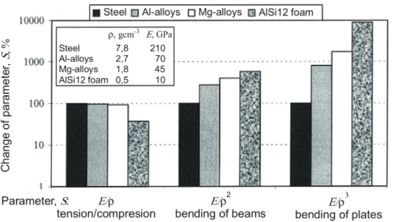
If specific stiffness (ratio of modulus of elasticity and density) of different materials is compared (Fig. 9) then it can be seen that in bending of beams and panels the aluminium foams show 10 to 100 times greater values than steel, and somewhat higher values than aluminium and magnesium alloys.
Comparing to steel, bulk aluminium and magnesium alloys aluminium foam show a better specific stiffness in cases of bending of beams and panels (Figure 9). This is the main reason for application of foams in lightweight stiff construction elements.
Aluminium foams in sandwich structures have a great potential for use in the lightweight and stiff structures [7, 8, 9, 25] when static or dynamic bending loadings are applied.
Steel Al-alloys Mg-alloys AlSi12 foam Steel Al-alloys Mg-alloys AlSi12 foam ρ, gcm-3 E, GPa 7,8 210 2,7 70 1,8 45 0,5 10 C ha ng e of p ar am et er , S , % Parameter, :S E/ρ tension/compresion E/ρ 2
bending of beams E/ρ
3
bending of plates Fig. 9.Parameter S – ratio of modulus of elasticity and density for different materials and loading methods (E – modulus of elasticity, r – density, value for steel: 100 %) [4] Sl. 9. Parametar S - omjer modula elastičnosti i gustoće za različite materijale i načine opterećenja (E – modul elastičnosti, r – gustoća, vrijednost za čelik: 100 %) [4]
Specific bending stiffness of aluminium foams is substantially increased in sandwich structures with foam cores.
In cases of high tensile stress metal foams usually behave very unfavourably. Therefore, e.g. the bending loaded parts are reinforced by grids of stainless steel, in the tensile stressed cross section zones [4]. In this case the stresses are trans-ferred from the foam to the reinforcing element.
Fig. 10 shows an example of how the reinforcements influence the behaviour of a beam made of AlSi12 foam of 81 % porosity, when bended.
Deflection ( ), mm f St re ss , M Pa
Reinforcement bottom longitudinally
Reinforcement top longitudinally Plain foam 30 25 20 15 10 5 0 0,0 0,5 1,0 1,5 2,0 2,5 3,0 3,5 4,0 4,5
Fig. 10. Influence of reinforcement on the behaviour in bending a beam made of AlSi12 foam of 81 % porosity [4]
Sl. 10. Utjecaj ojačavanja na ponašanje savojno opterećene grede od AlSi12 pjene sa 81 % poroznosti [4]
The main tasks of reinforcement are [22]:
– preventing foam collapse (stabilising effect), – increasing the surface layer thickness, – significant increase of fracture toughness,
– significant increase of bending strength (especially when the tensile loa -ded part is reinforced),
– significant increase in the energy absorption capacity, - increase in the bending stiffness, when the foam volume (thickness) is limited, – parts made of foam are more easily joined (welding is possible), limited
forming is possible after foaming.
The other possibility for increasing strength is precipitation hardening of some aluminium alloys (e.g. AlMgSi). The result is higher compressive and fa-tigue resistance [23, 24] or better bending resistance [26].
3.2 Moment of inertia and bending stiffness of the foamed aluminium
shapes
From theory and previous investigation [14] it could be concluded that the moment of inertia is a function of relative foam density (mass of solid materi-als), cell distribution and depth of surface skin. The second influential factor is the degree of uniform distribution of cell materials throughout the cross section. Therefore the cross sections with dense surface skin have different moments of inertia depending on skin thickness [14].The results of bending testing of the aluminium foamed panels with different thickness and depth of surface skin and sandwiches indicate (Fig. 11 - left) that the apparent modulus of elasticity de -creases with increasing thickness of the plates and in-creases with increasing ap-parent foam density according to the power-law.
The analyses show that the use of the apparent modulus of elasticity in the case of the specimens with a surface skin is not correct because the foamed panel is not a macroscopically homogeneous body but a certain type of sandwich. Be-cause of the surface skin, the apparent density of the specimen is much higher than actual foam’s density. The depth of surface skin contributes essentially to
the actual moment of inertia. It has been suggested [14] that the suitable
param-eter for defining of the foamed panels could be the square weight, i.e. the weight per unit area of the materials (for relative foam density lower than 0.4) - Fig. 12.
Fig. 11. Effect of the thickness, matrix alloy and density on the apparent modulus of elasticity of the foamed aluminium panels [14]
Sl. 11. Utjecaj debljine, vrste legure i gustoće na prividni modul elastičnosti aluminijskih ploča [14]
Fig. 12. Moment of inertia normalized to the sample’s width as a function of the square weight of various foamed aluminium panels and sandwiches (right: zoom of the diagram in the left) [14] Sl. 12. Moment tromosti sveden na širinu ispitnog uzorka kao funkcija mase po jedinici površine različitih ploča i sendviča od aluminijskih pjena (desno: povećan dio lijevog dijagrama) [14]
The recent investigations show [7, 10] that the higher bending strength as well as better bending stiffness can be achieved on the foamed panels reinforced
with expanded steel sheet (net).
Until now, the bending properties of foams and sandwiches have been tested on the plates with rectangular section only, and not on the other cross section shapes. The data for the bending stiffness and moments of inertia for different shapes have not been found.
3.2.1 Materials
and testing method
The main purpose of own investigation was testing and determining of ben-ding properties – benben-ding stiffness (EI) and moment of inertia (I) of the various shapes made from aluminium foam alloy AlSi10 with closed cells.
The different cross sections have been produced with powder metallurgical FOAMINAL-ALULIGHT process (Figure 3).
The specimens for testing have been foamed in an electrically heated furnace in the steel moulds with the defined cross section.
The cross-sections were round, quadratic, hexagonal and I-shaped from the same aluminium alloys AlSi10 and foam density of 1000 kg/m3 (Figure 14).
All specimens have the same length (200 mm), cross section area, volume (100 cm3), mass of precursor (100 g) and relative foam density (r/r
s = 0.37).
The cell mass and its distribution were relatively uniform and the surface skin was very thin, which are the starting points for the calculation of moment of inertia.
The four-point bending test was applied (Fig. 13) because in this case the bending moment has the constant values between the loading points: This test is not sensitive to local deformation like by three bending test which generate maxi-mum bending moment at the loading place (at the middle of the probe).
According to obtained bending characteristics (maximum load in elastic ran-ge and associated deflection) the bending stiffness (EI) and moment of inertia (I) have been determined for each cross section shape.
Fig. 13. Scheme of test specimen under four-point bending
The maximum elastic deflection depends on corresponding load, geometric characteristics of beam, modulus of elasticity and moment of inertia, according to the known relation:
(6) where: Fmax – maximum force in elastic range, N
l – length of testing specimen, mm
a – distance between the loading point and support, mm E – modulus of elasticity, MPa
I – moment of inertia, mm4.
Derived from this relation and known dimensions from Fig. 13, bending stiffness could be calculated from:
(7)
Fig. 14. The specimens of aluminium foam shapes after testing Sl. 14. Uzorci profila od aluminijskih pjena nakon ispitivanja
The curve flows at the Fig. 15 show that by equal loads in an elastic range an I-shaped section deforms in tension zone least, while a round one deforms most.
Fig. 15. Deflection vs. force in tension zone (bottom) – average values from the three test specimens [15]
Sl. 15. Progib u vlačnoj zoni kao funkcija opterećenja – srednja vrijednost ispitivanja od tri uzorka [15]
3.2.2 Calculation of bending stiffness
From Fig. 15 the critical load at a maximum elastic deformation can be determined for each shape. By means of these defined data and relation (7) the bending stiffness for each foamed shape has been calculated (Table 3).
As well as for solid materials, in comparison to the other cross sections, the I-shaped one has the highest bending rigidity. The qualitative relative proportions of EI to other section shapes are also the same as for homogeneous (solid) shapes.
Table 3 - Bending stiffness (EI) of the different foamed and solid shapes Tablica 3 - Savojna krutost (EI) različitih oblika punih i pjenastih presjeka
Shape
Foam shapes AlSi10
r/rs = 0.37 Solid shapes AlSi10 Relative ratio:
(EI)f
Nmm2 ratio of RelativeEI Nmm(EI)s2 ratio of RelativeEI
145∙106 1.00 1 365∙106 1.00 0.11
169∙106 1.16 1 447∙106 1.06 0.12
193∙106 1.33 1 435∙106 1.04 0.13
338∙106 2.33 3 800∙106 2.78 0.09
Average ratio 0.12
The average value of relative ratios
is similar for all section shapes, which indicates that the profile form has dominant influence on bending stiffness, at the equal relative density.
From these results and according to the common relation (1), the empirical expression between bending stiffness of foamed and solid shapes could initially be defined as:
(8)
The mean ratio
from Table 3 is: (9)
Derived from this expression for relative density r/rs = 0.37, results with the average value of exponent x = 2.1.
The proved value of exponent x should be defined after more testing with the larger number of specimens for each cross section shape with variation of relative densities.
When the value for modulus of elasticity is known, the moments of inertia
According to Fig. 7 and 8 and above stated relation (5) and expression (8) derived from the Table 3, modulus of elasticity for own foam specimens with relative density r/rs = 0.37 and apparent density of 1 000 kg/m3, the value for E
f is
approximately between 12 000 and 14 000 MPa. Based on E value of 12 000 MPa the calculated moments of inertia are presented in Table 4.
Table 4 - Calculated moments of inertia of the different foamed and solid shapes Tablica 4 - Izračunati momenti tromosti za različite pune i pjenaste oblike presjeka
Shape
Foam shapes AlSi10
Ef≈12 000 MPa, r/rs= 0.37 Solid shapesEs = 69 000 MPa AlSi10 Relative
ratio: If, mm4 Relative ratio of I Is, mm4 Rel. ratio of I 12 070 1.00 20 100 1.00 0.60 14 083 1.16 20 800 1.03 0.68 16 095 1.33 21 000 1.04 0.77 28 167 2.33 53 000 2.64 0.53 Average ratio 0.64 4 CONCLUSIONS
• Today's processes of manufacturing metal foams have not been characterised to a sufficient extent yet, and they are difficult to control so that this may result in great variation of their mechanical and other properties.
• However, metal foams provide the unique combination of several (seemingly contradictory) properties that, at the same time, cannot be achieved by any other conventional material.
• The recent research continually spread on other porous cellular architectures which includes: honeycombs, fiber networks, connected rods and wire mesh structures, connected hollow bodies, syntactic foams, metal foam-based com-posites, amorphous metallic foams, bio-inspired nano-porous structures etc. [27].
• The current developments are focused to the biomedical applications – or-thopaedic and dental implants (Ti-foams), nickel and steel foams for energy-related applications (batteries, fuel-cells, and engines), nano-porous materials for electrodes, catalyst, sensors, actuators or filtration applications etc. [28].
• The still imperfect structure of foams may be acceptable in a number of the demanding applications, if new approaches, new methods, and rules in de-signing are used, adapted to cellular materials. A number of methods for the analysis of the cellular structures are now in the phase of intensive deve-lopment.
• There may be difficulties in the design and analysis of the structures, such as e.g.: the geometry of the cellular part (outer layer) influence the structure and the mechanical properties, dispersion in local density (imperfections, density gradients), there is no typical size of pores – only the distribution of the sizes of pores, anisotropic structure (pore orientation) influenced by the shape of the part, deformation mechanisms depend on the material of the cell wall, great sensitivity to tensile stress (initiation of cracks).
• The preliminary results of bending testing confirm a theory that moment of inertia is a function of relative share of solid mass of materials (foam density) in a foamed cross section area.
• The shape of foamed profile has a significant influence on bending stiffness and on moment of inertia. I-shaped section shows the best bending stiffness comparing to other cross section shapes, the same as for solid shapes.
• Future investigations of bending stiffness will be directed to testing: – the larger number of specimens for each cross section shape, – the specimens with three different relative densities,
– verification the expressions (8) and (9),
– the influence of surface skin thickness and reinforcement on the bending properties of these cross sections.
Acknowledgments
This work was carried out within the research project Modelling of material properties and process parameters - No. 120-1201780-1779 financial supported by Ministry of Science, Education and Sport of the Republic of Croatia. Author would like to thank Gojko Marić, PhD and Željko Alar, PhD for manufacturing the foamed specimens and bending testing.
References
[1] L.J. Gibson, M.F. Ashby: Cellular solids: structure and properties (Second Ed.), Cambridge University Press, Cambridge, 1997.
[2] H. P. Degischer, B. Kriszt (eds): Handbook of cellular metals, Wiley-VCH Ver -lag, Weinheim, 2002.
[3] M. F. Ashby, A. G. Evans, N. A. Fleck, L. J. Gibson, J. W. Hutchinson, H. N. G. Wadley: Metal Foams: A Design Guide, Butterworth-Heinemann, Boston, Ox -ford, Auckland, Johannesburg, Melbourne, New Delhi, 2000.
[4] F. Simančik, J. Kovačik, N. Minarikova: Bending properties of foamed alu -minium panels and sandwiches, MRS Symposium Proceedings (Ed. by. D.S. Schwartz, D.S. Shih, A.G. Evans and H.N.G. Wadley, Vol. 521, Materials Re -search Society, Warrendale, Pennsylvania, 1998, p. 91
[5] K. Stobener, J. Baumeister, D. Lehmus, H. Stanzick, V. Zollner: Composites based on metallic foams. Phenomenology; production; properties and princi-ples, Proceedings of the International Conference Advanced Metallic Materials, Smolenice, Slovakia, 5-7 November 2003. pp. 281-286.
[6] F. Simančik, W. Rajner, R. Laag: Reinforced Alulight for structural use, Pro -ceeding of the Conference Processing and properties of lightweight cellular metals
and structures (TMS Annual Meeting), Seattle, 2002, p. 25
[7] F. Simančik, W. Rajner, R. Laag: Alulight-Aluminium foam for lightweight con -struction, In: SAE Technical paper Series 2000-01-0337. Warrendale: SAE, Inc., 2000, pp. 31-38
[8] F. Simančik, J. Jerz, J. Kovačik, P. Minar: Aluminium foam-a new light-weight structural material, Kovove Materialy, 35, 1997, p. 265
[9] H.-W. Seeliger: Aluminium Foam Sandwich (AFS) Ready for Market Introduc -tion, Advanced Engineering Materials 2004, 6, No.6, pp. 448-451.
[10] J. Kovačik, F. Simančik, J. Jerz, P. Tobolka: Reinforced Aluminium Foams, Pro -ceedings of the International Conference Advanced Metallic Materials, Smolen-ice, Slovakia, 5-7 November 2003. pp. 154-159.
[11] E. Andrews, W. Sanders, L.J. Gibson: Compressive and tensile behaviour of aluminium foams, Materials Science and Engineering A270 (1999), pp. 113-124 [12] C. Chen, A.-M. Harte, N.A. Fleck: The plastic collapse of sandwich beams with
a metallic foam core, Int. Journal of Mechanical Sciences 43(2001)9, pp. 1483-1506;
[13] W. Krach, T. Daxner, F.G. Rammerstorfer: Metallic Foams versus Human Bones, Proceedings of the EUROMAT Conference, Rimini, 2000, Paper No. 1160. [14] F. Simančik, W. Rajner, R. Laag: Reinforced Alulight for structural use, Pro
-ceeding of the Conference Processing and properties of lightweight cellular metals
[15] T. Filetin, G. Marić: Bending stiffness of foamed aluminium profiles, Book of Abstracts - Proceedings of the 5th Inter. Conference on Mechanics and
Materi-als in Design - M2D’2006, Porto 24-26 July 2006, p. 373-374 (full text on CD, 9
pages)
[16] T. Filetin, G. Marić, I. Kramer: Metal Foams in Shipbuilding, Brodogradnja 55(2005)3, pp. 1-10.
[17] J. Banhart: Metallschäume; MIT Verlag, Bremen, 1997.
[18] T.J. Lu, H.A. Stone, M.F. Ashby: Acta. Mater.. Vol. 46(1998), pp. 3619-3635. [19] Advanced Engineering Materials, Special Issue - Metal foams, Vol.2, No. 4,
2000.
[20] Advanced Engineering Materials, Special Issue on Cellular Metals, Vol.4, No. 10, 2002.
[21] T. Filetin, I. Kramer, G. Marić: Metal foams (in Croatian), Croatian Society for Materials and Tribology, Zagreb, 2003.
[22] F. Simančik: Aluminium Foams, Invited lecture at the seminar Advanced
Alu-minium Materials and Products, September 2003. šibenik, Croatia (ppt)
[23] B. Zettl, H. Mayer, S. E. Stanzl-Tschegg: Fatigue properties of Al–1Mg–0.6Si foam at low and ultrasonic frequencies, International Journal of Fatigue Vol. 23, Issue 7, August 2001, pp. 565-573
[24] D. Lehmhus, C. Marschner, J. Banhart, H. Bomas: Influence of heat treatment on compression fatigue of aluminium foams, Journal of Materials Science 37 (2002), pp. 3447– 3451.
[25] H. Meerkamm, W. Schweiger, R. F. Singer, F. Heinrich, W. Puri, W. Schmidt: Auslegung von Traversen für Hochleistungsbestückungs-automaten aus zellu -laren Werkstoffen, VDI Berichte 1595 - Inovative Produkte durch neue Werkstoffe, VDI-Verlag, Düsseldorf, 2001. pp. 283-299.
[26] T. Filetin, G. Marić: Bending resistance of aluminium foams after age harden -ing, Proceedings of Inter. Conf. New Challenges in Heat Treatment and Surface Engineering - in honour of prof. B. Liščić, Cavtat, 09-12.06.2009, pp. 267-270. [27 ...Advanced Engineering Materials, Special Issue - Highly Porous Metals and
Ceramics, Wiley VCH, Vol 10, No.3, 2008.
[28] ...Advanced Engineering Materials, Special Issue - Metallic Foams, Wiley VCH, Vol 10, No.9, 2008.
Savojna krutost aluminijskih pjena
S a ž e t a k
Ćelijaste strukture metala su pokušaj oponašanja sličnih prirodnih struk -tura (kosti, drvo, školjke i sl.) s ciljem postizanja lakih konstrukcija, ali i kom -binacije još nekoliko povoljnih svojstava.
Najraširenije u primjeni su aluminijske pjene zbog sljedećih svojstava: vrlo dobra izolacijska svojstva (toplinska i zvučna), mala gustoća (masa), vi -soka krutost u sendvič konstrukcijama, vrlo dobro prigušenje energije udara, otpornost na koroziju, negorivost, vrlo dobra recikličnost i dr. Smatra se da barem četiri od nabrojenih poželjnih svojstava (prednosti) moraju biti zado -voljene za optimalnu primjenu metalne pjene u odnosu prema drugim mate-rijalima. Gotovo sva svojstva u osnovi su određena tipom ćelija (zatvorene ili otvorene), njihovom veličinom, tj. relativnom gustoćom. Na oblik, veličinu i raspodjelu ćelija najviše utječe primijenjen postupak proizvodnje.
Za niz potrebnih svojstava u primjeni važnije je ponašanje pjena pri tlač -nom opterećenju nego pri vlač-nom opterećenju. Pjene s otvorenim ćelijama imaju vrlo dobro definiranu granicu stlačivanja. Pri tom naprezanju ćelije počinju teći uslijed savijanja. Zatvorene ćelije pokazuju mnogo složenije po -našanje. Naprezanje veličine granice stlačivanja izaziva zgušnjavanje pjene sve do konačne deformacije zgušnjavanja. Ovakvo specifično ponašanje pri tlačenju osnova je izvrsnog prigušenja energije udara metalnih pjena sa zatvo -renim ćelijama. Usporedi li se specifična krutost (odnos modula elastičnosti i gustoće) različitih materijala tada je vidljivo da kod savijanja štapova i ploča aluminijske pjene pokazuju 10 do 100 puta veće vrijednosti od čelika, a ne -što više vrijednosti od aluminijskih i magnezijskih legura. Specifična čvrstoća aluminijskih pjena (omjer granice tečenja i gustoće) posebno je povoljna, u odnosu prema čeliku, aluminiju i magneziju, kod savojno opterećenih ploča. U slučajevima velikih vlačnih naprezanja metalne pjene se najčešće nepovolj -no ponašaju. Zbog toga se primjerice savoj-no opterećeni dijelovi ojačavaju mrežama od nehrđajućeg čelika i to u vlačno napregnutim zonama presjeka. U tom slučaju se naprezanja prenose s pjene na ojačavajući element.
Rad je usmjeren na prikaz rezultata ispitivanja i određivanja savojne kru -tosti različitih oblika presjeka profila od aluminijskih pjena, koja je vrlo važna za analizu ponašanja lakih i krutih konstrukcijskih elemenata. Procesom me -talurgije praha Foaminal-Alulight oblikovani su okrugli, kvadratni, šesterokut -ni i I-profili. Plinom oslobođene čestice rastvorene u polučvrstoj fazi je meto -da proizvodnje metalnih pjena kod koje se prah čistog metala ili legure miješa s prahom TiH2. Nakon toga se ta mješavina sabija u poluproizvod (precursor) u obliku šipke ili trake. Poluproizvod se u obliku malih komadića stavlja u kalup i zagrijava na temperaturu nešto višu od solidusa. Pri tome dolazi do raspadanja TiH2 i stvaranja visokoporoznog materijala.
Profili su oblikovani pjenjenjem legure AlSi10 na gustoću od 1000 kg/m3,a svi profili su imali jednake površine poprečnog presjeka i obujam. Provedeno je ispitivanje savijanjem u četiri točke. Iz elastičnog dijela krivulje u dijagramu
sila-progib izračunata je savojna krutost (EI) svakog presjeka. I-profil ima naj -veću savojnu krutost u odnosu prema drugim oblicima presjeka, što se pokla -pa s relativnim odnosima savojne krutosti takvih oblika homogenih presjeka. Predložena je opća relacija između savojne krutosti pjenastih i punih profila, koja uključuje relativnu gustoću pjene.
Ključne riječi: aluminijske pjene; mehanička svojstva; savojna krutost
Prof. dr. sc. Tomislav Filetin
Član suradnik HAZU University of Zagreb,
Faculty of Mechanical Engineering and Naval Architecture, Department of Materials
Ivana Lučića 5 10 000 Zagreb [email protected]
![Fig. 1. Natural cellular materials: (a) cork, (b) balsa, (c) sponge, (d) trabecular bone, (e), coral (f), cuttlefish bone, (g) Iris leaf, (h) plant stalk [1], (i) aluminium foam closed cell structure, j) open cells metal foams [2]](https://thumb-ap.123doks.com/thumbv2/123dok/1817735.2646516/2.785.123.507.434.817/natural-cellular-materials-sponge-trabecular-cuttlefish-aluminium-structure.webp)
![Fig. 2. Overview of the different ways of processing cellular metals [2]](https://thumb-ap.123doks.com/thumbv2/123dok/1817735.2646516/3.785.135.649.242.575/fig-overview-different-ways-processing-cellular-metals.webp)
![Fig. 4. Compression curves for two types of aluminium foams [2]](https://thumb-ap.123doks.com/thumbv2/123dok/1817735.2646516/7.785.218.564.176.545/fig-compression-curves-types-aluminium-foams.webp)
![Fig. 5. Tensile stress-strain curves for three types of aluminium foams [11]](https://thumb-ap.123doks.com/thumbv2/123dok/1817735.2646516/8.785.174.610.434.738/fig-tensile-stress-strain-curves-types-aluminium-foams.webp)
![Tablica 1- Mehanička svojstva metalnih pjena [3]](https://thumb-ap.123doks.com/thumbv2/123dok/1817735.2646516/9.785.117.670.670.939/tablica-mehanička-svojstva-metalnih-pjena.webp)
![Fig. 6. Parameter R – ratio of strength and density, for different materials and loading conditions (R e – yield strength of material, r - density, value of steel: 100 %) [4]](https://thumb-ap.123doks.com/thumbv2/123dok/1817735.2646516/10.785.181.603.230.454/parameter-strength-different-materials-conditions-strength-material-density.webp)
![Fig. 8. Elasticity modulus vs. aluminium foam density [13]](https://thumb-ap.123doks.com/thumbv2/123dok/1817735.2646516/11.785.160.620.249.579/fig-elasticity-modulus-vs-aluminium-foam-density.webp)
![Fig. 11. Effect of the thickness, matrix alloy and density on the apparent modulus of elasticity of the foamed aluminium panels [14]](https://thumb-ap.123doks.com/thumbv2/123dok/1817735.2646516/14.785.121.660.163.377/effect-thickness-matrix-density-apparent-modulus-elasticity-aluminium.webp)
