171 PHYWE Systeme GmbH &Co. KG · D - 37070 Göttingen Laboratory Experiments Physics
X X
X X
X
X X
X X
X X
X X
X X
X
1000
800
600
400
200
0
1,0 2,0 3,0 4,0 plastic
air
Principle:
The electric constant 0 is
deter-mined by measuring the charge of a plate capacitor to which a voltage is applied. The dielectric constant is
determined in the same way, with plastic or glass filling the space between the plates.
Tasks:
1. The relation between charge Q
and voltage Uis to be measured using a plate capacitor.
2. The electric constant 0 is to be
determined from the relation measured under point 1. 3. The charge of a plate capacitor is
to be measured as a function of the inverse of the distance between the plates, under con-stant voltage.
Electrostatic charge Qof a plate capacitor as a function of the applied volt-age Uc, with and without dielectric (plastic) between the plates (d= 0.98 cm)
4. The relation between charge Q
and voltage Uis to be measured by means of a plate capacitor, between the plates of which dif-ferent solid dielectric media are introduced. The corresponding dielectric constants are deter-mined by comparison with meas-urements performed with air between the capacitor plates. Plate capacitor, d= 260 mm 06220.00 1
Plastic plate 283⫻283 mm 06233.01 1 Glass plates f. current conductors 06406.00 1 High-value resistor, 10 MΩ 07160.00 1 Universal measuring amplifier 13626.93 1 High voltage supply unit, 0-10 kV 13670.93 1
Capacitor/case 1/0.22 µF 39105.19 1
Voltmeter, 0.3-300 VDC, 10-300 VAC 07035.00 1 Connecting cord, l= 100 mm, green-yellow 07359.15 1 Connecting cord, l= 500 mm, red 07361.01 1 Connecting cord, l= 500 mm, blue 07361.04 1 Connecting cord, 30 kV, l= 500 mm 07366.00 1 Screened cable, BNC, l = 750 mm 07542.11 1 Adapter, BNC socket - 4 mm plug 07542.20 1
Connector, T type, BNC 07542.21 1
Adapter, BNC-plug/socket 4 mm 07542.26 1
What you need:
Complete Equipment Set, Manual on CD-ROM included
Dielectric constant of different materials
P2420600
What you can learn about …
Maxwell’s equations Electric constant Capacitance of a plate
capacitor Real charges Free charges
Dielectric displacement Dielectric polarisation Dielectric constant
Q
nAs
Uc
Related topics
Maxwell’s equations, electric constant, capacitance of a plate capacitor, real charges, free charges, dielectric displacement, dielectric polarisation, dielectric constant.
Principle
The electric constant e0 is determined by measuring the
charge of a plate capacitor to which a voltage is applied. The dielectric constant is determined in the same way, with plas-tic or glass filling the space between the plates.
Equipment
Plate capacitor, d= 260 mm 06220.00 1 Plastic plate 283⫻283 mm 06233.01 1 Glass plates f. current conductors 06406.00 1 High-value resistor, 10 MOhm 07160.00 1 Universal measuring amplifier 13626.93 1 High voltage supply unit, 0-10 kV 13670.93 1 Capacitor/case 1/0.22 µF 39105.19 1 Voltmeter, 0.3-300 VDC, 10-300 VAC 07035.00 1 Connecting cord, l= 100 mm, green-yellow 07359.15 1 Connecting cord, l= 500 mm, red 07361.01 1 Connecting cord, l= 500 mm, blue 07361.04 1 Connecting cord, 30 kV, l= 500 mm 07366.00 1 Screened cable, BNC, l= 750 mm 07542.11 1 Adapter, BNC socket - 4 mm plug 07542.20 1 Connector, T type, BNC 07542.21 1 Adapter, BNC-plug/socket 4 mm 07542.26 1
Tasks
1. The relation between charge Q and voltage U is to be measured using a plate capacitor.
2. The electric constant e0is to be determined from the
rela-tion measured under point 1.
3. The charge of a plate capacitor is to be measured as a func-tion of the inverse of the distance between the plates, under constant voltage.
4. The relation between charge Q and voltage U is to be measured by means of a plate capacitor, between the plates of which different solid dielectric media are intro-duced. The corresponding dielectric constants are deter-mined by comparison with measurements performed with air between the capacitor plates.
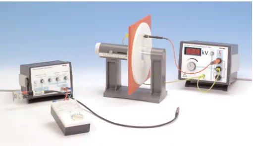
Set-up and procedure
The experimental set-up is shown in fig. 1 and the corre-sponding wiring diagram in fig. 2. The highly insulated capac-itor plate is connected to the upper connector of the high volt-age power supply over the 10 MΩprotective resistor. Both the middle connector of the high voltage power supply and the opposite capacitor plate are grounded over the 220 nF capac-itor. Correct measurement of the initial voltage is to be assured by the corresponding adjustment of the toggle switch on the unit. The electrostatic induction charge on the plate capacitor can be measured over the voltage on the 220 nF capacitor, according to equation (4). The measurement amplifier is set to high input resistance, to amplification factor 1 and to time constant 0.
24206-00 PHYWE series of publications • Laboratory Experiments • Physics • © PHYWE SYSTEME GMBH & Co. KG • D-37070 Göttingen
2
To start with, the surface of the capacitor plates is determined by means of their radius. The experiment is carried out in two parts:
1. In the first part, the distance between the plates of the plate capacitor is varied under constant voltage, and the charge on the capacitor plates is measured. The linear relation between charge and plate capacitor voltage is then verified.
Measurement data allow to determine the electric constant
0,
using equation (4).
Be sure not to be near the capacitor during measurements, as otherwise the electric field of the capacitor might be dis-torted.
2. In the second part, the dependence of the electrostatic induction charge from voltage, with and without plastic plate (without air gap!), is examined in the space between the plates, with the same distance between the plates. The ratio between the electrostatic induction charges allows to deter-mine the dielectric constant e0of plastic. The dielectric
con-stant of the glass plate is determined in the same way.
Theory and evaluation
Electrostatic processes in vacuum (and with a good degree of approximation in air) are described by the following integral form of Maxwell’s equations:
(1)
(2)
where E씮is the electric field intensity, Qthe charge enclosed by the closed surface A, e0 the electric constant and s a
closed path.
If a voltage Ucis applied between two capacitor plates, an
elec-tric fieldE씮will prevail between the plates, which is defined by:
(cf. figure 3). Due to the electric field, electrostatic charges of the opposite sign are drawn towards the surfaces of the capacitor. As voltage sources do not generate charges, but only can separate them, the absolute values of the opposite electrostatic induction charges must be equal.
Assuming the field lines of the electric field always to be per-pendicular to the capacitor surfaces of surface A, due to sym-metry, which can be experimentally verified for small distanc-es d between the capacitor plates, one obtains from equa-tion (1):
(3) Q
e0
⫽E ·A⫽Uc · A · 1 d
Uc⫽
冮
2
1 ESd rS
冯
SEd SS⫽0冰
AE
S
d AS⫽
Q
e0 Fig. 2: Wiring diagram.
Fig. 3: Electric field of a plate capacitor with small distance between the plates, as compared to the diameter of the plates. The dotted lines indicate the volume of integra-tion.
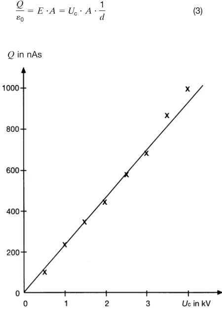
Fig. 4: Electrostatic charge Qof a plate capacitor as a function of the applied voltage Uc(d= 0.2 cm)
The volume indicated in fig. 3, which only encloses one capacitor plate, was taken as volume of integration. As the surface within the capacitor may be displaced without chang-ing the flux, the capacitor field is homogeneous. Both the flow and the electric field E outside the capacitor are zero, because for arbitrary volumes which enclose both capacitor plates, the total enclosed charge is zero.
The charge Qof the capacitor is thus proportional to voltage; the proportionality constant Cis called the capacitance of the capacitor.
(4)
The linear relation between charge Qand voltage Uapplied to the otherwise unchanged capacitor is represented in fig. 4. Equation (4) further shows that the capacitance C of the capacitor is inversely proportional to the distance dbetween the plates:
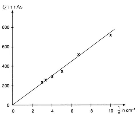
(5)
For constant voltage, the inverse distance between the plates, and thus the capacitance, are a measure for the amount of charge a capacitor can take (cf. fig. 5). If inversely U,Q,dand Awere measured, these measurement data allow to calculate the electric constant e0:
(6)
In this example of measurement, one obtains e0= 8.8 · 10–12
As/(Vm), as compared to the exact value of
e0= 8.8542 · 10–12As/(Vm)
Equations (4), (5) and (6) are valid only approximately, due to the assumption that field lines are parallel. With increasing dis-tances between the capacitor plates, capacitance increases, which in turn systematically yields a too large electric constant from equation (6). This is why the value of the electric constant should be determined for a small and constant distance be-tween the plates (cf. fig. 4).
e0⫽
Things change once insulating material (dielectrics) are insert-ed between the plates. Dielectrics have no free moving charge carriers, as metals have, but they do have positive nuclei and negative electrons. These may be arranged along the lines of an electric field. Formerly nonpolar molecules thus behave as locally stationary dipoles. As can be seen in fig. 6, the effects of the single dipoles cancel each other macroscopically inside the dielectric. However, no partners with opposite charges are present on the surfaces; these thus have a stationary charge, called a free charge.
The free charges in turn weaken the electric field E씮of the real charges Q, which are on the capacitor plates, within the di-electric.
The weakening of the electric field E씮within the dielectric is expressed by the dimensionless, material specific dielectric constant e(e= 1 in vacuum):
(7)
where E씮0is the electric field generated only by the real charg-es Q. Thus, the opposite field generated by the free chargcharg-es must be
(8)
Neglecting the charges within the volume of the dielectric macroscopically, only the free surface charges (±Q) generate effectively the opposite field:
(9)
where pis the total dipole moment of the surface charges. In the general case of an inhomogeneous dielectric, equation (9) becomes:
(10)
where P씮– total dipole moment per unit volume – is called di-electric polarisation.
If additionally a D씮-field (dielectric displacement) is defined:
D씮= e· e0· E
씮
(11)
whose field lines only begin or end in real (directly measurable) charges, the three electric magnitudes, field intensity E씮, di-electric displacement D씮and dielectric polarisation P씮are relat-ed to one another through the following equation:
D씮= e0· E
Fig. 5: Electrostatic charge Qof a plate capacitor as a function of the inverse distance between the capacitor plates
d–1(U
c= 1.5 kV).
Fig. 6: Generation of free charges in a dielectric through polarisation of the molecules in the electric field of a plate capacitor.
24206-00 PHYWE series of publications • Laboratory Experiments • Physics • © PHYWE SYSTEME GMBH & Co. KG • D-37070 Göttingen
4
If the real charge Qremains on the capacitor, whilst a dielec-tric is inserted between the plates, according to definition (3), voltage Uc between the plates is reduced as compared to
voltage Uvacin vacuum (or to a good approximation, in air) by
the dielectric constant:
(12)
Similarly, one obtains from the definition of capacitance (4):
C = e· C vac (13)
The general form of equation (4) is thus:
(14)
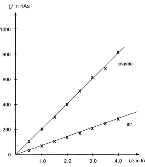
In fig. 7, charge Q on the capacitor is plotted against the applied plate voltage Ucfor comparison to the situation with and without plastic plate between the capacitor plates, all other conditions remaining unchanged: thus, for the same voltage, the amount of charge of the capacitor is significantly increased by the dielectric, in this example by a factor of 2.9. If the charges obtained with and without plastic (equations [4] and [14]) are divided by each other:
(15)
the obtained numerical value is the dielectric constant of the plastic.
For the glass plates, a value of e= 9.1 is obtained similarly.
Qplastic
Qvacuum⫽e
Q⫽e · e0 · A
d · Uc
Uc⫽
Uvac
e
In order to take into consideration the above described influ-ence of free charges, Maxwell’s equation (1) is generally com-pleted by the dielectric constant eof the dielectric which fills
the corresponding volume:
(16)
Thus, equation (14) becomes equation (4).
Measurement results
Measurement of the electric constant:
A= 0.0531 m2 Uc= 1.5 kV C= 218 nF
A= 0.0531 m2 d= 0.2 cm C= 218 nF
Measurement of dielectric constant
Plastic: A= 0.0531 m2 d= 0.98 cm C= 218 nF
Glass: d= 0.17 cm U莥 = 5.8 V Q= 1.264 mAs Uc= 500 V
eglass= 9.1
Uc[kV] 0.5 1.0 1.5 2.0 2.5 3.0 3.5 4.0
U[V] 0.5 0.92 1.35 1.8 2.3 2.8 3.1 3.7
Q[nAs] 109 201 294 392 501 610 676 807
Q—d
Ae0
1 —
Uc 4.6 4.2 4.1 4.1 4.2 4.3 4.0 4.2
Uvac[V] 0.16 0.32 0.51 0.62 0.78 0.95 1.12 1.3
Qvac[nAs] 35 70 111 135 170 207 244 283
Q/Qvac 3.1 2.9 2.6 2.9 2.9 2.9 2.9 2.9
Uc[kV] 0.5 1.0 1.5 2.0 2.5 3.0 3.5 4.0
U[V] 0.5 1.1 1.6 2.05 2.65 3.15 4.0 4.6
Q[nAs] 109 240 348 447 578 687 872 1003
e0[pAs/Vm] 8.2 9.0 8,7 8.4 8.7 8.6 9.4 9.5
U[V] 3.3 2.4 1.6 1.35 1.2 1.1
d[cm] 0.10 0.15 0.20 0.25 0.30 0.35
1/d[cm–1] 10.0 6.7 5.0 4.0 3.3 2.9
Q[nAs] 719 523 350 294 262 240
e0[pAs/Vm] 9.00 9.85 8.75 9.25 9.85 10.50
冰
Ae · e0 · E S
d AS⫽
冰
DS
d AS⫽Q
Fig. 7: Electrostatic charge Qof a plate capacitor as a function of the applied voltage Uc, with and without dielectric
(plastic) between the plates (d= 0.98 cm)