A Compact and Compliant External
Pipe-Crawling Robot
Puneet Singh and G. K. Ananthasuresh
Abstract—The focus of this paper is on the practical aspects of design, prototyping, and testing of a compact, compliant external pipe-crawling robot that can inspect a closely spaced bundle of pipes in hazardous environments and areas that are inaccessible to humans. The robot consists of two radially deployable compliant ring actuators that are attached to each other along the longitu-dinal axis of the pipe by a bidirectional linear actuator. The robot imitates the motion of an inchworm. The novel aspect of the com-pliant ring actuator is a spring-steel comcom-pliant mechanism that converts circumferential motion to radial motion of its multiple gripping pads. Circumferential motion to ring actuators is pro-vided by two shape memory alloy (SMA) wires that are guided by insulating rollers. The design of the compliant mechanism is de-rived from a radially deployable mechanism. A unique feature of the design is that the compliant mechanism provides the necessary kinematic function within the limited annular space around the pipe and serves as the bias spring for the SMA wires. The robot has a control circuit that sequentially activates the SMA wires and the linear actuator; it also controls the crawling speed. The robot has been fabricated, tested, and automated. Its crawling speed is about 45 mm/min, and the weight is about 150 g. It fits within an annular space of a radial span of 15 mm to crawl on a pipe of 60-mm outer diameter.
Index Terms—Compliant mechanism, inchworm motion, pipe crawler, pipe inspection, shape memory alloy (SMA).
I. INTRODUCTION
P
IPE crawlers can be classified as internal and external crawlers: Internal ones crawl inside the pipe, while ex-ternal ones traverse on the outside. They can also be classi-fied, based on locomotion methods, as wheeled crawler, walk-ing crawler, slidwalk-ing crawler, and inchworm crawler [1]–[5]. Wheeled crawlers work well only on even surfaces. Walking crawlers require sensors and sophisticated control to have the necessary gait and to avoid obstacles. Sliding crawlers need tracks or treads. In comparison with other crawlers, inchworm crawlers are less cumbersome and are less affected by irregular-ities. Different variations of inchworm crawlers are proposed in the literature (see, e.g., [6]–[11]).Manuscript received March 10, 2012; revised June 29, 2012; accepted August 18, 2012. Date of publication September 7, 2012; date of current version February 1, 2013. This paper was recommended for publication by Associate Editor Y. Choi and Editor B. J. Nelson upon evaluation of the reviewers’ com-ments. This work was supported in part by the Government of India under a Board of Research in Nuclear Sciences Grant. This paper is an enhanced and comprehensive version of three papers that presented different aspects of the work in national conferences held in India, as cited in this paper.
The authors are with the Department of Mechanical Engineering, Indian Institute of Science, Bangalore 560012, India (e-mail: puneet@ mecheng.iisc.ernet.in; [email protected]).
Color versions of one or more of the figures in this paper are available online at http://ieeexplore.ieee.org.
Digital Object Identifier 10.1109/TRO.2012.2214560
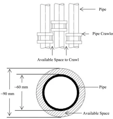
Fig. 1. Space constraints of an external pipe crawler. The side view of a bundle of three pipes is shown at the top, while the cross-sectional view of the space available for one pipe is shown at the bottom.
Many of the crawlers reported in the literature are internal crawlers. However, the focus of this paper is not on internal crawlers because of the need to inspect the thickness of a pipe carrying corrosive fluids. External inchworm-type pipe crawlers have received modest attention in the literature. Schempf et al.[8] reported an external inchworm crawler using a four-bar linkage to generate clamping and releasing actions. The bulky rigid-body mechanisms used in it made it occupy a lot of space outside the pipe because its function was to remove and bag asbestos. Fukudaet al.[9] also designed external pipe crawler using a winch mechanism and used sophisticated control system. Choiet al.[10], [11] reported pneumatically actuated external crawlers that used hinged clamps to hold the pipe. The pipe-inspection robot of Chatzakoset al.[12] used omnidirec-tional wheels and linkages. Except the crawlers reported by Choi et al.[10], [11], other external crawlers are not compact to meet the requirements of the application considered in this paper.
The application that motivated our work is an environment in which there is a bundle of pipes with limited space between them. Typically, only 10–20-mm radial space is available around a pipe of 60-mm outer diameter. This means that with a radial span of 15 mm, there is an annular space between circles of 90 and 60 mm diameters (see Fig. 1). Thus, the main challenge addressed in this study is an external crawler that is compact in terms of mechanism and actuation. The crawlers reported by
252 IEEE TRANSACTIONS ON ROBOTICS, VOL. 29, NO. 1, FEBRUARY 2013
Choiet al.in [10], [11] seem to be compact but use pneumatic actuation, which needs flexible pipes to crawl along. We use shape memory alloy (SMA) wires for actuation and joint-free compliant design for the mechanism. Using SMA wire has an advantage over pneumatic actuation in that the crawler can be untethered if it is equipped with a battery. The compliant mech-anism concept is amenable for further reduction in size without putting undue demand on manufacturability.
Fig. 1 shows the main features of the crawler: It has two rings that hold the pipe tightly when there is no actuation; it crawls like an inchworm by alternately releasing the grip of one of its rings with actuation, and moving to and fro with a linear actuator that connects the rings. The clamping mechanism and linear actuators of the inchworm crawler must fit within the narrow space indicated in Fig. 1. Hence, it necessitated a compact mechanism and actuator. Since multiple dedicated crawlers are needed for all the pipes, it is also imperative that the cost is kept low.
This implies that the design should be simple, use as few parts as possible, and minimize assembly. This challenge is met by a unibody compliant ring actuator actuated by SMA wires. The ring actuator has a compliant mechanism that converts circum-ferential motion to radial motion of its multiple gripping pads. Unlike the hinged clamps used in [11], the ring actuator can apply equal pressure on all its pads to have uniform gripping on the pipe.
The ring actuator and SMA wires operate synergistically: SMA provides the compact actuation to the mechanism, while the compliant mechanism serves as the bias spring for SMA in cyclical operation. As stated earlier, the inchworm motion is achieved by a pair of compliant ring actuators connected by bidi-rectional linear actuators. One of the rings translates forward, while the other is clamped and the linear actuator is extended. Then, the translated ring is clamped and the first ring advances as the linear actuator reduces the length between the rings. A sim-ple electronic circuit controls the cyclical operation. Apart from the design of the joint-free compliant ring actuator, the other challenges faced in this study include electrical isolation of the SMA wires from the metal used in the ring actuator, speed of crawling based on heating/cooling times of SMA wires, a linear actuator that is compact and adequately powerful, and design for manufacturability of the entire crawler robot.
The remainder of this paper is organized as follows. The design of the ring actuator is explained in Section II. Section III deals with the characterization of SMA wires used in this study. Sections IV and V describe the clamp-and-push “inchworm” motion and integration of the control electronics. Section VI presents the details of prototyping and the results of testing. Concluding remarks are in Section VII.
II. COMPLIANTRINGACTUATOR
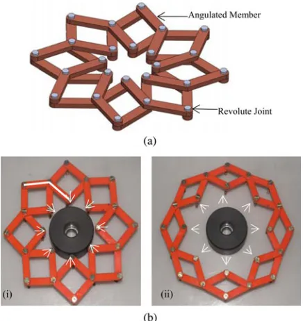
In recent years, radially deployable mechanisms have gained popularity in various forms: retractable structures (see, e.g., [13]), solar arrays (see, e.g., [14]), and toys (www.hoberman.com). These mechanisms are overconstrained (i.e., they have negative degrees of freedom as per theGr¨ubler
Fig. 2. (a) Geometric model of the radially deployable mechanism. (b) Ra-dially deployable mechanism: (i) clamping and (ii) releasing. It is made of 16 angulated members connected with 24 revolute joints and arranged in two layers. One angulated element is shown in Fig. 2(b-i).
formula [15]) but have special geometry that permits them to move radially in or out, as shown in Fig. 2(a) and (b). Such a mechanism, which is known as the Hoberman linkage [www.hoberman.com], can be used to clamp around a pipe and release the grip upon actuation. However, there is a problem with it because all of its points move radially outward and need sliding guidance or need to be pulled away using anchors lo-cated outside. This issue was resolved with a general theory of planar radially deployable mechanisms presented by Patel and Ananthasuresh [16]. A new type of mechanism that has few points that move along a circle was identified in that work. It enables circumferential actuation to achieve the radial deploy-ment and avoids the need for radial guidance.
The circumferentially actuated mechanism is illustrated in Fig. 3(a) and (b). However, this multibody jointed mechanism is also not suitable to fit into the narrow annular space such as the one shown in Fig. 1. Rather, it will be either difficult or not economical to manufacture hinged parts of small size. There-fore, we developed a radially deployable compliant mechanism with the same kinematic behaviors the one in Fig. 3(a) and (b) and satisfying the space constraint. This is done by using elas-tic deformation instead of joint-based motion as in compliant mechanisms [17].
A. Radially Deployable Compliant Mechanism
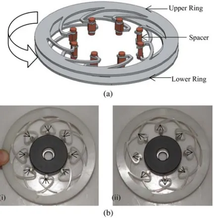
Fig. 3. (a) Geometric model of the circumferentially actuated radially deploy-able mechanism. (b) Circumferentially actuated radially deploydeploy-able mechanism: (i) clamping and (ii) releasing. It consists of two identical layers each containing four identical triangles and one ring. The triangles are attached to each other and the ring with 16 revolute joints. Each triangle is attached to one triangle in the same layer, one ring, and one triangle in the other layer.
Fig. 4. (a) Geometric model of the circumferentially actuated radially deploy-able compliant mechanism. (b) Circumferentially actuated radially deploydeploy-able compliant mechanism prototype: (i) undeformed and (ii) deformed. This is made of two identical layers of compliant segments connected to each other with eight revolute joints.
of certain shape attached to each other at eight interior points. The two layers are arranged one over the other wherein one is a mirror image of the other about an in-plane axis. When the ring portions of each layer are rotated circumferentially relative to each other, eight attachment points move radially.
To understand the radially deployable compliant mechanism shown in Fig. 4(a) and (b), consider a single compliant segment
Fig. 5. (a) Deformation of a single compliant segment. (b) Deformation of a single compliant ring.
Fig. 6. Geometric model of the SMA-actuated radially deployable compliant mechanism.
254 IEEE TRANSACTIONS ON ROBOTICS, VOL. 29, NO. 1, FEBRUARY 2013
Fig. 7. SMA-actuated radially deployable compliant mechanism (a) with a single wire and (b) with two SMA wires.
B. Shape-Memory-Alloy-Actuated Radially Deployable Compliant Mechanism
Using the principle of elastic deformation depicted in Fig. 5(a) and (b), the pads of the ring actuator move radially when its two rings are rotated circumferentially relative to each other. This differential circumferential motion to the two rings is provided by two SMA wires. The ends of each of the two SMA wires are first elongated, wrapped around half of the rings, capped with plastic clips, and then crimped firmly to two rings so that they can be pulled together when the SMA wire contracts upon heating. We use spring-steel to make the compliant rings because the restoring force to bring the SMA wires had to be sufficiently large (which is not possible with plastic materials unless the size is large) and to have good elastic behavior for repetitive action. Since spring-steel in an electrical conductor, it warrants proper electrical insulation between the SMA wires and the rings. For this, several insulating roller guides are used. Rolling guides solve two problems: electrical insulation and guiding the wire with reduced friction. It can be noticed in Fig. 6 that the ring actuator is compact in the radial direction around a circular object on which it is to be mounted. Its annular span in the radial direction is only 15 mm, while its overall radius is 90 mm. This compact design was arrived at after a few trials reported earlier by us in conference presentations [18], [19].
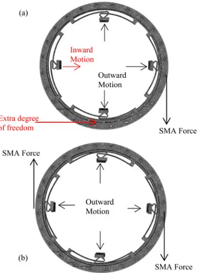
In one of our earlier designs [18], [19], which is shown in Fig. 7(a), we had used a single SMA wire that was put along the circumference of the rings. This caused nonuniform motion of the gripping pads. This is because the mechanism, as well as the radially deployable rigid-body shown in Fig. 3(a) and (b), has an extra degree of freedom that makes the two rings translate relative to each other. This will prevail unless the two rings
Fig. 8. Previous prototypes of pipe crawler. (a) SMA strips for linear actuation. (b) SMA helical springs for linear actuation.
are made to only rotate relative to each other. When a single SMA wire is wrapped around the ring, it pulls unevenly on the four compliant mechanism segments. Hence, the four gripping pads move unequally to the extent that one pad moves in the inward direction while the rest of the three move in the outward direction. This is confirmed by finite-element simulation done in ABAQUS [www.simulia.com].
To solve this problem, we used two SMA wires instead of one. Two SMA wires were put in such a way that both SMA wires apply the force uniformly on the ring and avoid the undesirable extra degree of freedom. Its simulation is shown in Fig. 7(b), in which it can be seen that all gripping pads move equally in the outward direction by 1.5 mm. In ABAQUS simulation, we assumed that the lower ring is fixed and the forces were applied on the upper ring, as shown in Fig. 7(a) and (b). Tetrahedral finite elements were used in ABAQUS simulation, and the mesh was made sufficiently fine to ensure convergence. We noticed that using four SMA springs is even better than using two, but it leads to structural complexity in terms of capping plastic clips and electrical connections.
In our previous attempts [18], [19] at prototyping the pipe crawler with the ring actuator, we attempted to use SMA strips custom-made in U-shape or as helical springs. These are shown in Fig. 8(a) and (b). SMA strips needed a lot of current to heat up and actuate, and worse yet, they needed a lot of time to cool back to room temperature. SMA helical springs suffered from excessive lateral flexibility. Therefore, SMA actuation is limited only to the ring actuator in the final design and prototype [20].
III. SHAPEMEMORYALLOYWIRE AS ANACTUATOR
Fig. 9. Phase diagram of SMA with compliant mechanism.
primarily in the latter mode although the first is needed to pre-stress the SMA wires. When an SMA wire is electrothermally heated by passage of electric current, it heats up and shrinks as it transforms to its martensite state from the austenite state, as shown in Fig. 9. The shortening of the wire causes the relative circumferential motion of the rings. Compliant segments trans-form this to amplified radial motion at the gripping pads, as per the principle illustrated in Fig. 5(a) and (b). This releases the grip on the circular object, i.e., pipe. Upon turning off the elec-tric current, the wires cool and reach the martensite state again. Then, the restoring force of the compliant segments pulls the wires back to their stressed states (see atomic level schematic shown in Fig. 9). This cycle repeats as many times as needed provided that the original state is restored in terms of stress in the SMA wires and temperature.
A. Characterization of Shape Memory Alloy
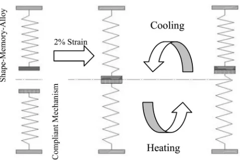
The principle of using SMA material as an actuator is shown in Fig. 10. It shows the SMA wire as a spring stretched from its “memory shape” at room temperature and connected to a load or a bias spring (here, the compliant mechanism). Since SMA exhibits pseudoplasticity in this condition, it stretches and stays that way. After this, the SMA wire is heated so that it can return to its memory shape and pull the load or the bias spring in this process. When the SMA wire cools down to the room temperature, it is the load or the bias spring that pulls the SMA back to the stressed state. Otherwise, reheating does not make any further movement. Thus, the load or bias spring plays a crucial role here. If the bias spring is not stiff enough, the SMA wire does not return to the sufficiently stressed state, and hence, the stroke of actuation will be reduced. If the load/bias spring is too stiff, the SMA will give a very small stroke. Therefore, the stiffness value is important to make repeated cyclical motion possible. The stiffness calculations are explained in the next section.
B. Stiffness Characterization of the Shape Memory Alloy Wire
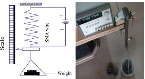
In order to match the stiffness of the complaint mechanism with the SMA wire, we performed an experiment with the SMA wire to characterize its stiffness. The SMA wire that we used
Fig. 10. Actuation of SMA wire with load/bias spring.
needs to be stretched up to 2% strain before assembling onto the device because it was trained to recover a maximum strain of 2% for unlimited number of cycles. We used 1-mm diameter Ni–Ti– Cu SMA wires (National Aerospace Laboratories, Bangalore, India). From the manufacturers, it is known that the wire can exert a stress of about 100 MPa, which for a 1-mm diameter wire translates to about 78.54-N force
F =σ×Across section =78.54 N.
The length of the wire and the prestrain in it had to be chosen carefully to exert adequate force and displacement that match those of the compliant segments. Only then, repeatable operation is possible. In other words, the stiffness of the SMA wire and the compliant segments should be matched. Therefore, it was imperative that the SMA wires be properly characterized.
The experimental setup to characterize the SMA wires is shown in Fig. 11. The wire was prestretched by about 1.75%. As the wire was heated, there was deformation in the SMA wire. To see the deformation in the wire against different applied weights, we applied weights from 1 to 8 kg. With 8-kg weight, the deformation was 4 mm, indicating that the wire is able to contract against a force of as much as 78 N. To calculate the stiffness in the martensite phase, we took the 226-mm-long SMA wire and fixed it at one end, while the other end was attached to 8-kg weight. The SMA wire deformed with the weight by 1 mm. Therefore, the stiffness of SMA wire in the martensite phase is calculated as 78.48 kN/m
KM artensite Phase=L δ =
8×9.81
1 =78.48 kN/m.
256 IEEE TRANSACTIONS ON ROBOTICS, VOL. 29, NO. 1, FEBRUARY 2013
Fig. 11. Schematic of experimental setup for SMA wire characterization.
in cooling phase. We repeated this experiment five times and found stiffness in the cooling phase to be 26.16 kN/m
KC o oling Phase =L δ =
8×9.81
3 =26.16 kN/m
KSM A C o olingPhase < KC om pliant M echanism.
Now, to make the repetitive motion possible, the stiffness of compliant ring should be greater than the stiffness of SMA wire in the cooling phase. Only then, the compliant ring will stretch the SMA wire back to the stressed state. The stiffness of the com-pliant ring was calculated to be 69.11 kN/m by finite-element simulation [see Fig. 7(b)]. This stiffness value is more than the stiffness of the SMA wire in the cooling phase. Therefore, it ensures repetitive cyclic motion.
C. Thermal Characterization of the Shape Memory Alloy Wire
It is important to understand the electrothermal behavior of the SMA wire and the entire ring actuator. Two issues arise here: 1) ensuring that the ring cools to room temperature within reasonable time after one cycle of operation and 2) ensuring that all SMA wires heat to 40◦C transition temperature with 2 V. For 1), we performed an experiment on the ring actuator and the SMA wire and measured the temperatures. We usedK-type
thermocouples to measure the temperature shown in Fig. 12(a). The dotted line in the graph shows the temperature of the SMA wire, while the other line shows the temperature of the spring-steel portion. It can be noticed that it takes only about 1 s to heat, while it takes 9 s to cool. Thus, it takes about 10 s to complete a cycle. It is worth noting that it is the cooling time that decides the overall cycle time. To make it faster than 10 s, one would need to use a cooling mechanism such as a fan or Peltier cooler, which comes at the expeese of more complexity.
To address the second issue, we performed 2-D transient electrothermal modeling of SMA wire using CMOSOL Multi-physics [www.comsol.com] to calculate the temperature profile by applying 2-V electric potential. The temperature profile is shown in Fig. 12(b) at time 2 s. It can be seen that the en-tire wire reaches 40 ◦C. This distribution continues to be so when the voltage is sustained for longer time. Hence, all of the SMA wire uniformly undergoes phase transition. The material properties used in thermal modeling were thermal conductiv-ity= 18 W/(m·K), density =6800 Kg/m3, and resistivity=
Fig. 12. (a) Temperature versus time in the experiment. (b) Temperature dis-tribution of the SMA wire in its electrothermal modeling at time 2 s.
7.6e-7Ω·m for the SMA wire. The two ends of the wire were held at room temperature in this modeling, which is justifiable because the spring-steel portion does not heat much, as can be seen in Fig. 12(a).
IV. CLAMP-AND-PUSHMOTION
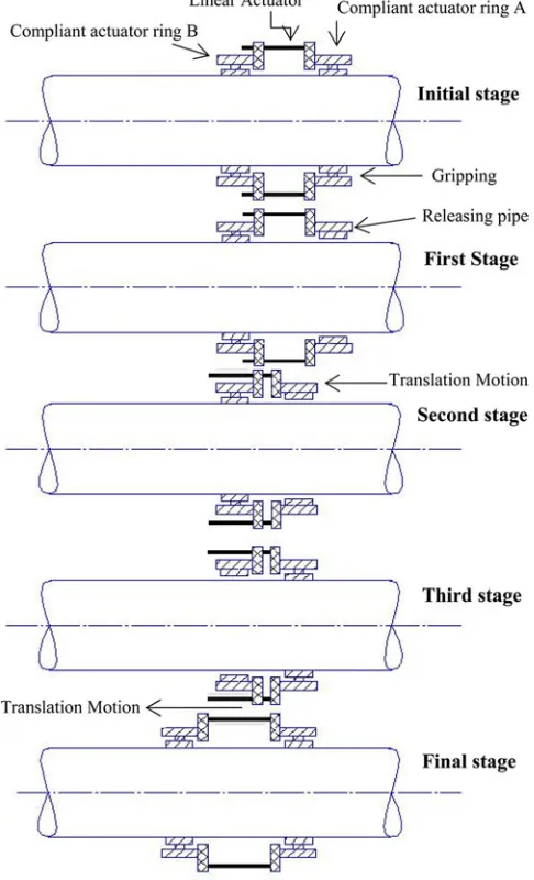
As demonstrated in Fig. 13, the robot consists of two SMA-actuated radially deployable compliant ring actuators, which are labeled A and B.
In order to crawl to the left, ring B grips the pipe tightly and stays unactuated, while ring A is actuated to release its grip. The translation actuator pushes ring A closer to ring B. At this stage, actuation to ring A is stopped, thus making it grip the pipe again while ring B is released and translation actuators are activated in reverse direction. Now, ring B is pushed to the left. This constitutes one cycle and leads to a finite movement to the right. By repeating this cycle, the device crawls over the pipe. By reversing the roles of rings A and B in a cycle, the crawling direction can be changed. This concept works for an internal crawler too, but here we focus on only the external crawler within limited space.
V. ELECTRONICSINTEGRATION
Fig. 13. Schematic illustration of a clamp-and-push concept of a pipe crawler robot.
sequence. As stated before, we had used SMA strips and springs for translation actuation [see Fig. 8(a) and (b)] which took a lot of time to heat and cool. Therefore, we decided to change the translation actuator to a geared DC motor with lead screw.
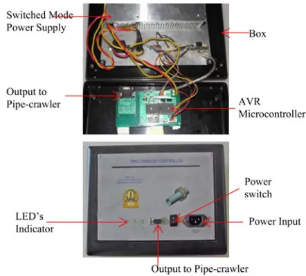
The current-driving circuit on a printed circuit board is used to effect the cyclical operation of triggering the passage and stoppage of current in the two pairs of SMA wires and one set of translation actuators (shown in Fig. 14). The circuit has ATMEL-made AVR microcontroller with three current sources in parallel, as shown in Fig. 15.
A switched mode power supply (SMPS) of 400-W capac-ity was taken from a personal computer to supply the current needed for the SMA wires and translation actuators. The current can be switched by the microcontroller and the value of current can be set by the three potentiometers. High-power MOSFETs (metal–oxide field-effect transistors) are used to get the current loads needed for the actuators. The microcontroller is interfaced by universal serial bus converter. A command-driven program is used to set the various actuator timings to control the speed.
Fig. 14. Cyclic chart for the pipe crawler robot.
The sequence of the actuation is programmed into the micro-controller so that switching of the actuators is automatic.
VI. PROTOTYPING ANDASSEMBLY
Compliant radially deployable mechanism was assembled using two compliant rings, as shown in Fig. 16. The com-pliant rings, as stated earlier, convert the circumferential motion into radial motion. First, we designed a geometric model of compliant rings in SolidWorks [www.solidworks.com] and generated the machining code—the G-code—for wire-cut electrodischarge-machining (EDM) using customized ELAPT software. The compliant rings were made out of spring steel (AISI 1080; EN 42 J) cut on a wire-cut EDM. Since the two rings are in two different parallel planes, they were soft-soldered at the gripping pads. Two Ni–Ti–Cu SMA wires were connected in between the compliant rings with the help of a plastic clip and a brass crimpable tube. The SMA wires were connected in opposite directions. The insulating rollers on which the SMA wire sits can be seen in Fig. 17 along with the other parts. In-sulating acrylic rollers were made on the CO2 laser machine. To increase the friction coefficient between the pipe and grip-ping pads, a butyl layer of 1-mm thickness was affixed onto the gripping pads. A full assembly of SMA-actuated ring actuator is shown in Fig. 17.
258 IEEE TRANSACTIONS ON ROBOTICS, VOL. 29, NO. 1, FEBRUARY 2013
Fig. 15. Electronic schematic diagram for cyclic operation of the robot.
VII. TESTING ANDRESULTS
Fig. 19 shows the test setup of SMA-actuated radial deploy-able compliant ring actuator. The setup shows the ring actuator put on a pipe that is set vertically. Since the outer diameter of the pipe is larger than the diameter of the circle passing through the four clamping points, there is a gripping force of 1.8 N (per clamping pad) applied on the pipe, as calculated by the finite-element simulation in ABAQUS. With 2-V potential, the ring loosens the grip on the pipe because of the radially outward movement of the gripping pads. This experiment was done 20 times to calculate the deformation in the clamping pads without mounting it on the pipe. The maximum deformation on one clamping pad was 1.2 mm with a standard deviation of 0.02 mm. When we look at the movement of all four pads, there is about 2.4-mm change in the diameter of the circle passing through the outer edges of the gripping pads in the unactuated and actuated configurations.
Fig. 16. SMA-actuated radial deployable compliant ring actuator.
Fig. 17. Complete prototype of the crawling robot.
Fig. 18. Electronic control system for pipe crawler.
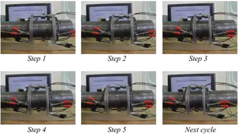
Fig. 20. Demonstration of pipe crawler robot in horizontal pipe.
Fig. 21. Demonstration of pipe crawler robot on a pipe set at 30◦incline.
Figs. 20 and 21 show the test setup of the pipe crawler robot. The setup shows the robot put on a pipe that is set horizontal and at 30◦. Initially, the gripping pads of both the compliant ring actuators tightly hold the pipe. When the SMA wires of the first ring are activated, the compliant mechanism releases the grip on the pipe. At this time, the translation actuator is activated to bring the ring actuators closer together, as shown in Steps 2 and 3 in Figs. 20 and 21. After this, the first ring is deactivated to grip the pipe. This is followed by release of the grip of the second ring actuator. After this, the translation actuator is activated in the reverse direction, as shown in Steps 4 and 5 in Figs. 20 and 21. That leads the robot to its initial configuration but moved by 30 mm in 40 s as well. Thus, it was observed that the measured crawling speed in both configurations is 45 mm/min.
There is room for improvement in the crawling robot in terms of increasing its speed and reducing the size. This is largely de-pendent on the linear actuator used to effect the relative motion between the pair of ring actuators. It should be noted that the SMA wire actuation is improved to the extent possible to take as little time as possible to heat and cool. It takes about 1 s to heat up and then 9 s to cool down an SMA wire. This is the limiting step in this device. Hence, a suitable motor that is not much more expensive than the one used now would help in-crease the crawling speed. The robot is not yet tested on curved pipes, but it could be done by including flexible joints at the connection points of the linear actuator. The lead screw and DC motor, if made smaller, can further reduce the overall size of the crawling robot and make it the curvature of the pipe sharper
than is currently possible. Friction and sliding may also need to be modeled.
The main contribution of the work presented here is the com-pactness, simplicity, and cost effectiveness of the SMA-actuated ring actuator. It may be useful for other applications as well. Another contribution is the concept of designing the stiffness of the bias spring (here, the compliant ring actuator) to match that of the SMA wire. This too is important in many applications beyond the one presented here.
VIII. CLOSURE
In this paper, we have presented a compact external pipe crawler robot that follows clamp-and-push motion and imitates inchworm motion. Its compactness is a result of radially deploy-able compliant mechanism and SMA actuation. The compliant mechanism used here was designed on the basis of a kinematic theory developed for radially deployable linkages. A novel fea-ture of the design is that the compliant mechanism provides the necessary kinematic function within limited space and serves as the bias spring for the SMA wires. The stiffness of the SMA wire and that of the compliant mechanism were matched so that they work synergistically. A description of its working principle, design details, and practical aspects were provided. A control circuit is built to effect the cyclical triggering in a sequence of six steps. The total cycle time is 40 s, and the distance crawled is 30 mm per cycle. Thus, a crawling speed of 45 mm/min was achieved in the prototype. Other sizes and speeds are also pos-sible by changing the design of the compliant mechanism in the ring actuator.
ACKNOWLEDGMENT
This work is a result of synergistic effort of several students of the Multidisciplinary Multi-scale Devices and Design group at the Indian Institute of Science, Bangalore, India. The authors would like to thank G. Balaji and P. Biradar for initial designs and prototypes; B. M. V. Kumar and A. R. Kumar for their help in fabrication; and D. K. Badige and S. Yamadagni for their help in building the electronics unit. The SMA wires were made by C. N. S. Krishna and Ramaiah in Dr. S. Bhaumik’s group at the National Aerospace Laboratories, Bangalore. They also thank A. Haruray, who brought the application to their attention and helped with the specifications for the crawler. This help is gratefully acknowledged.
REFERENCES
[1] K. Suzumori, T. Miyagawa, M. Kimura, and Y. Hasegawa, “Micro inspec-tion robot for 1-in pipes,”IEEE/ASME Trans. Mechatronics, vol. 4, no. 3, pp. 286–292, Sep. 1999.
[2] S. G. Roh and H. R. Choi, “Differential-drive in-pipe robot for moving inside urban gas pipelines,”IEEE Trans. Robot., vol. 21, no. 1, pp. 1–17, Feb. 2005.
[3] H. T. Roman and B. A. Pellegrino, “Pipe crawling inspection robots: An overview,”IEEE Trans. Energy Convers., vol. 8, no. 3, pp. 576–583, Sep. 1993.
[4] A. Zagler and F. Pfeiffer, “MORTIZ, a pipe crawler for tube junctions,” in
260 IEEE TRANSACTIONS ON ROBOTICS, VOL. 29, NO. 1, FEBRUARY 2013
[5] J. A. G´alvez, P. G. de Santos, and F. Pfeiffer, “Intrinsic tactile sens-ing for the optimization of force distribution in a pipe crawlsens-ing robot,”
IEEE/ASME Trans. Mechatronics, vol. 6, no. 1, pp. 26–35, Mar. 2001. [6] D. K. Haas, “Small diameter pipe crawler,” Savannah River Nat. Lab. Tech
briefs, U.S. patent 6 427 602, 2002.
[7] P. Breedveld, D. E. van der Kouwe, and M. A. J. van Gorp, “Locomotion through the intestine by means of rolling stents,” presented at the Amer. Soc. Mech. Eng. Design Eng. Tech. Conf. Comput. Inf. Eng. Conf., Salt Lake City, UT, Sep. 28/Oct. 2, 2004, Paper DETC2004/MECH 57380. [8] H. Schempf, E. Mutschler, B. Chemel, and S. Boehmke, “BOA II & Pipe
Taz: Robotic pipe-asbestos insulation abatement systems,” inProc. IEEE Int. Conf. Robot. Autom., Albuquerque, NM, Apr. 1997, pp. 52–59. [9] T. Fukuda, H. Hosokai, and M. Otsuka, “Autonomous pipeline inspection
and maintenance robot with inch worm mobile mechanism,” inProc. IEEE Int. Conf. Robot. Autom., Mar. 1987, pp. 539–544.
[10] C. Choi, S. Jung, and S. Kim, “Feeder pipe inspection robot with inch-worm mechanism using pneumatic actuators,” Int. J. Control Autom. Syst., vol. 4, no. 1, pp. 87–95, 2006.
[11] C. Choi, B. Park, and S. Jung, “The design and analysis of a feeder pipe inspection robot with an automatic pipe-tracking system,” IEEE/ASME Trans. Mechatronics, vol. 15, no. 5, pp. 736–745, Oct. 2010.
[12] P. Chatzakos, Y. P. Markopoulos, K. Hrissagis, and A. Khalid, “On the development of a modular external-pipe crawling Omni-directional mobile robot,” inProc. 8th Int. Conf. Climbing Walking Robot. Support Technol. Mobile Mach. Part 11, 2006, pp. 693–700.
[13] T. Buhl, F. V. Jensen, and S. Pellegrino, “Shape optimization of cover plates for retractable roof structures,”Comput. Struct., vol. 88, pp. 1227– 1236, 2004.
[14] K. A. Faist and G. J. Wiens, “Parametric study on the use of Hoberman mechanisms for reconfigurable antenna and solar arrays,” inProc. IEEE Aerosp. Conf., Mar., 2010, pp. 6–13.
[15] G. Erdman, G. N. Sandor, and S. Kota,Mechanism Design: Analysis and Synthesis. Englewood Cliffs, NJ: Prentice–Hall, 2001.
[16] J. Patel and G. K. Ananthasuresh, “A kinematic theory for radially foldable planar linkages,” Int. J. Solids Struct., vol. 44, pp. 6279–6298, 2007. [17] L. L. Howell,Compliant Mechanisms. New York: Wiley, 2001. [18] G. Balaji, P. Biradar, C. N. Saikrishna, K. Venkata Ramaiah, S. K.
Bhaumik, A. Haruray, and G. K. Ananthasuresh, “An SMA-actuated, compliant mechanism-based pipe-crawler,” presented at the Int. Conf. Smart Mater., Struct., Syst., Bangalore, India, Jul. 2008, Paper no. 96. [19] B. M. Vinod Kumar, D. K. Badige, S. Hegde, and G. K.
Ananthasuresh, “An improved compact compliant mechanism for an ex-ternal pipe-crawler,” presented at the 14th Nat. Conf. Mach. Mechanisms, Durgapur, India, Dec. 2009.
[20] P. Singh and G. K. Ananthasuresh, “An SMA-actuated, compact, compli-ant ring-actuator with uniform deformation,” presented at the 15th Nat. Conf. Mach. Mechanisms, Chennai, India, Dec. 2011.
[21] M. G. Faulkner, J. J. Amalra, and A. Bhattacharyya, “Experimental in-vestigation and thermal and electrical properties Ni-Ti-Cu shape memory wires,” Int. J. Smart Mater. Struct., vol. 9, pp. 632–639, 2009.
Puneet Singhreceived the B.Tech. degree in mechan-ical and automation engineering from Guru Gobind Singh Indraprastha University, Delhi, India, in 2010. He is currently a Research Assistant with the Multidisciplinary Multiscale Devices and Design Laboratory, Department of Mechanical Engineering, Indian Institute of Science, Bangalore, India. His re-search interests include robotics, biorobotics, brain– machine interfaces, microsystems, compliant mech-anisms, and biomechanics.
G. K. Ananthasureshreceived the B.Tech. degree from the Indian Institute of Technology Madras, Chennai, India, in 1989 and the Ph.D. degree from the University of Michigan, Ann Arbor, in 1994.
He is currently a Professor of mechanical en-gineering with the Indian Institute of Science, Bangalore, India. He worked as a Postdoctoral Re-search Associate with the Massachusetts Institute of Technology, Cambridge (during 1995–1996), taught at the University of Pennsylvania, Philadelphia (dur-ing 1996–2004), and served as a Visit(dur-ing Scientist with the University of Cambridge, Cambridge, U.K., and the Katholike Uni-vesiteit, Leuven, Belgium. He is on the Editorial Boards of eight journals. He is a coauthor of more than 180 papers in journals and conferences, as well as a textbook, two edited books, and ten book chapters. His current research interests include compliant mechanisms, kinematics, multidisciplinary design optimization, microsystems technology, micro- and mesoscale manufacturing, protein design, and cellular biomechanics.