Preface xviii Nomenclature xxvi
C H A P T E R
O N E
BASICS OF HEAT TRANSFER
1
1-1
Thermodynamics and Heat Transfer 2Application Areas of Heat Transfer 3 Historical Background 3
1-2
Engineering Heat Transfer 4Modeling in Heat Transfer 5
1-3
Heat and Other Forms of Energy 6Specific Heats of Gases, Liquids, and Solids 7 Energy Transfer 9
1-4
The First Law of Thermodynamics 11Energy Balance for Closed Systems (Fixed Mass) 12 Energy Balance for Steady-Flow Systems 12 Surface Energy Balance 13
1-5 Heat Transfer Mechanisms 17 1-6 Conduction 17
Thermal Conductivity 19 Thermal Diffusivity 23
1-7 Convection 25 1-8 Radiation 27
1-9 Simultaneous Heat Transfer Mechanisms 30 1-10 Problem-Solving Technique 35
A Remark on Significant Digits 37 Engineering Software Packages 38 Engineering Equation Solver (EES) 39 Heat Transfer Tools (HTT) 39
Topic of Special Interest:
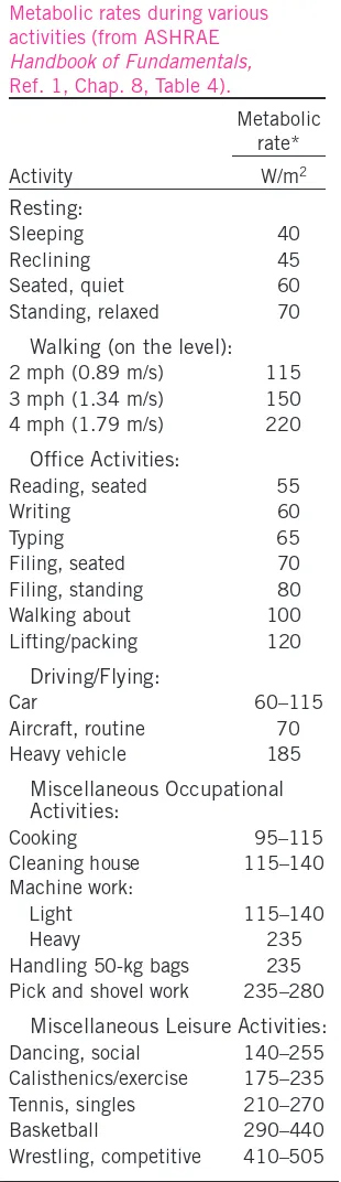
Thermal Comfort 40 Summary 46
References and Suggested Reading 47 Problems 47
C H A P T E R
T W O
HEAT CONDUCTION EQUATION
61
2-1 Introduction 62
Steady versus Transient Heat Transfer 63 Multidimensional Heat Transfer 64 Heat Generation 66
2-2 One-Dimensional
Heat Conduction Equation 68
Heat Conduction Equation in a Large Plane Wall 68 Heat Conduction Equation in a Long Cylinder 69 Heat Conduction Equation in a Sphere 71 Combined One-Dimensional
Heat Conduction Equation 72
2-3 General Heat Conduction Equation 74
Rectangular Coordinates 74 Cylindrical Coordinates 75 Spherical Coordinates 76
2-4 Boundary and Initial Conditions 77
1 Specified Temperature Boundary Condition 78 2 Specified Heat Flux Boundary Condition 79 3 Convection Boundary Condition 81 4 Radiation Boundary Condition 82 5 Interface Boundary Conditions 83 6 Generalized Boundary Conditions 84 2-5 Solution of Steady One-Dimensional
Heat Conduction Problems 86 2-6 Heat Generation in a Solid 97
2-7 Variable Thermal Conductivity, k(T) 104
Topic of Special Interest:
A Brief Review of Differential Equations 107 Summary 111
References and Suggested Reading 112 Problems 113
C H A P T E R
T H R E E
STEADY HEAT CONDUCTION
127
3-1 Steady Heat Conduction in Plane Walls 128
The Thermal Resistance Concept 129
3-4 Heat Conduction in Cylinders and Spheres 146
Multilayered Cylinders and Spheres 148 3-5 Critical Radius of Insulation 153
3-6 Heat Transfer from Finned Surfaces 156
Fin Equation 157 Fin Efficiency 160 Fin Effectiveness 163 Proper Length of a Fin 165
3-7 Heat Transfer in Common Configurations 169
Topic of Special Interest:
Heat Transfer Through Walls and Roofs 175 Summary 185
References and Suggested Reading 186 Problems 187
C H A P T E R
F O U R
TRANSIENT HEAT CONDUCTION
209
4-1 Lumped System Analysis 210
Criteria for Lumped System Analysis 211
Some Remarks on Heat Transfer in Lumped Systems 213
4-2 Transient Heat Conduction in Large Plane Walls, Long Cylinders, and Spheres with Spatial Effects 216 4-3 Transient Heat Conduction in
Semi-Infinite Solids 228 4-4 Transient Heat Conduction in
Multidimensional Systems 231
Topic of Special Interest:
Refrigeration and Freezing of Foods 239 Summary 250
References and Suggested Reading 251 Problems 252
C H A P T E R
F I V E
NUMERICAL METHODS
IN HEAT CONDUCTION
265
5-1 Why Numerical Methods? 266
1 Limitations 267 2 Better Modeling 267 3 Flexibility 268
5-3 One-Dimensional Steady Heat Conduction 272
Boundary Conditions 274
5-4 Two-Dimensional
Steady Heat Conduction 282
Boundary Nodes 283 Irregular Boundaries 287
5-5 Transient Heat Conduction 291
Transient Heat Conduction in a Plane Wall 293 Two-Dimensional Transient Heat Conduction 304
Topic of Special Interest:
Controlling Numerical Error 309 Summary 312
References and Suggested Reading 314 Problems 314
C H A P T E R
S I X
FUNDAMENTALS OF CONVECTION
333
6-1 Physical Mechanism on Convection 334
Nusselt Number 336
6-2 Classification of Fluid Flows 337
Viscous versus Inviscid Flow 337 Internal versus External Flow 337
Compressible versus Incompressible Flow 337 Laminar versus Turbulent Flow 338
Natural (or Unforced) versus Forced Flow 338 Steady versus Unsteady (Transient) Flow 338 One-, Two-, and Three-Dimensional Flows 338 6-3 Velocity Boundary Layer 339
Surface Shear Stress 340
6-4 Thermal Boundary Layer 341
Prandtl Number 341
6-5 Laminar and Turbulent Flows 342
Reynolds Number 343
6-6 Heat and Momentum Transfer in Turbulent Flow 343 6-7 Derivation of Differential
Convection Equations 345
Equations and Similarity 356 6-10 Functional Forms of Friction and
Convection Coefficients 357 6-11 Analogies between Momentum
and Heat Transfer 358
Summary 361
References and Suggested Reading 362 Problems 362
C H A P T E R
S E V E N
EXTERNAL FORCED CONVECTION
367
7-1 Drag Force and Heat Transfer in External Flow 368
Friction and Pressure Drag 368 Heat Transfer 370
7-2 Parallel Flow over Flat Plates 371
Friction Coefficient 372 Heat Transfer Coefficient 373
Flat Plate with Unheated Starting Length 375 Uniform Heat Flux 375
7-3 Flow across Cylinders and Spheres 380
Effect of Surface Roughness 382 Heat Transfer Coefficient 384
7-4 Flow across Tube Banks 389
Pressure Drop 392
Topic of Special Interest:
Reducing Heat Transfer through Surfaces 395 Summary 406
References and Suggested Reading 407 Problems 408
C H A P T E R
E I G H T
INTERNAL FORCED CONVECTION
419
8-1 Introduction 420
8-2 Mean Velocity and Mean Temperature 420
Laminar and Turbulent Flow in Tubes 422
8-3 The Entrance Region 423
Entry Lengths 425
Pressure Drop 433
Temperature Profile and the Nusselt Number 434 Constant Surface Heat Flux 435
Constant Surface Temperature 436 Laminar Flow in Noncircular Tubes 436
Developing Laminar Flow in the Entrance Region 436
8-6 Turbulent Flow in Tubes 441
Rough Surfaces 442
Developing Turbulent Flow in the Entrance Region 443 Turbulent Flow in Noncircular Tubes 443
Flow through Tube Annulus 444 Heat Transfer Enhancement 444 Summary 449
References and Suggested Reading 450 Problems 452
C H A P T E R
N I N E
NATURAL CONVECTION
459
9-1 Physical Mechanism of Natural Convection 460 9-2 Equation of Motion and
the Grashof Number 463
The Grashof Number 465
9-3 Natural Convection over Surfaces 466
Vertical Plates (Tsconstant) 467 Vertical Plates (q·sconstant) 467 Vertical Cylinders 467
Inclined Plates 467 Horizontal Plates 469
Horizontal Cylinders and Spheres 469
9-4 Natural Convection from Finned Surfaces and PCBs 473
Natural Convection Cooling of Finned Surfaces (Tsconstant) 473
Natural Convection Cooling of Vertical PCBs (q·sconstant) 474
Mass Flow Rate through the Space between Plates 475
9-5 Natural Convection inside Enclosures 477
Effective Thermal Conductivity 478 Horizontal Rectangular Enclosures 479 Inclined Rectangular Enclosures 479 Vertical Rectangular Enclosures 480 Concentric Cylinders 480
Concentric Spheres 481
Problems 501
C H A P T E R
T E N
BOILING AND CONDENSATION
515
10-1 Boiling Heat Transfer 516 10-2 Pool Boiling 518
Boiling Regimes and the Boiling Curve 518 Heat Transfer Correlations in Pool Boiling 522 Enhancement of Heat Transfer in Pool Boiling 526
10-3 Flow Boiling 530
10-4 Condensation Heat Transfer 532 10-5 Film Condensation 532
Flow Regimes 534
Heat Transfer Correlations for Film Condensation 535
10-6 Film Condensation Inside Horizontal Tubes 545 10-7 Dropwise Condensation 545
Topic of Special Interest:
Heat Pipes 546 Summary 551
References and Suggested Reading 553 Problems 553
C H A P T E R
E L E V E N
FUNDAMENTALS OF THERMAL RADIATION
561
11-1 Introduction 562 11-2 Thermal Radiation 563 11-3 Blackbody Radiation 565 11-4 Radiation Intensity 571
Solid Angle 572
Intensity of Emitted Radiation 573 Incident Radiation 574
Radiosity 575
Spectral Quantities 575
11-5 Radiative Properties 577
Emissivity 578
Absorptivity, Reflectivity, and Transmissivity 582 Kirchhoff’s Law 584
The Greenhouse Effect 585
Problems 599
C H A P T E R
T W E L V E
RADIATION HEAT TRANSFER
605
12-1 The View Factor 606 12-2 View Factor Relations 609
1 The Reciprocity Relation 610 2 The Summation Rule 613 3 The Superposition Rule 615 4 The Symmetry Rule 616
View Factors between Infinitely Long Surfaces: The Crossed-Strings Method 618
12-3 Radiation Heat Transfer: Black Surfaces 620 12-4 Radiation Heat Transfer:
Diffuse, Gray Surfaces 623
Radiosity 623
Net Radiation Heat Transfer to or from a Surface 623 Net Radiation Heat Transfer between Any
Two Surfaces 625
Methods of Solving Radiation Problems 626
Radiation Heat Transfer in Two-Surface Enclosures 627 Radiation Heat Transfer in Three-Surface Enclosures 629
12-5 Radiation Shields and the Radiation Effect 635
Radiation Effect on Temperature Measurements 637
12-6 Radiation Exchange with Emitting and Absorbing Gases 639
Radiation Properties of a Participating Medium 640 Emissivity and Absorptivity of Gases and Gas Mixtures 642
Topic of Special Interest:
Heat Transfer from the Human Body 649 Summary 653
References and Suggested Reading 655 Problems 655
C H A P T E R
T H I R T E E N
HEAT EXCHANGERS
667
13-1 Types of Heat Exchangers 668
13-2 The Overall Heat Transfer Coefficient 671
Fouling Factor 674
13-5 The Effectiveness–NTU Method 690 13-6 Selection of Heat Exchangers 700
Heat Transfer Rate 700 Cost 700
Pumping Power 701 Size and Weight 701 Type 701
Materials 701
Other Considerations 702 Summary 703
References and Suggested Reading 704 Problems 705
C H A P T E R
F O U R T E E N
MASS TRANSFER
717
14-1 Introduction 718
14-2 Analogy between Heat and Mass Transfer 719
Temperature 720 Conduction 720 Heat Generation 720 Convection 721
14-3 Mass Diffusion 721
1 Mass Basis 722 2 Mole Basis 722
Special Case: Ideal Gas Mixtures 723
Fick’s Law of Diffusion: Stationary Medium Consisting of Two Species 723
14-4 Boundary Conditions 727
14-5 Steady Mass Diffusion through a Wall 732 14-6 Water Vapor Migration in Buildings 736 14-7 Transient Mass Diffusion 740
14-8 Diffusion in a Moving Medium 743
Special Case: Gas Mixtures at Constant Pressure and Temperature 747
Diffusion of Vapor through a Stationary Gas: Stefan Flow 748
Equimolar Counterdiffusion 750
14-9 Mass Convection 754
Analogy between Friction, Heat Transfer, and Mass Transfer Coefficients 758
Limitation on the Heat–Mass Convection Analogy 760 Mass Convection Relations 760
C H A P T E R
F I F T E E N
COOLING OF ELECTRONIC EQUIPMENT
785
15-1 Introduction and History 786
15-2 Manufacturing of Electronic Equipment 787
The Chip Carrier 787 Printed Circuit Boards 789 The Enclosure 791
15-3 Cooling Load of Electronic Equipment 793 15-4 Thermal Environment 794
15-5 Electronics Cooling in Different Applications 795 15-6 Conduction Cooling 797
Conduction in Chip Carriers 798 Conduction in Printed Circuit Boards 803 Heat Frames 805
The Thermal Conduction Module (TCM) 810
15-7 Air Cooling: Natural Convection and Radiation 812
15-8 Air Cooling: Forced Convection 820
Fan Selection 823
Cooling Personal Computers 826
15-9 Liquid Cooling 833 15-10Immersion Cooling 836
Summary 841
References and Suggested Reading 842 Problems 842
A P P E N D I X
1
PROPERTY TABLES AND CHARTS
(SI UNITS)
855
Table A-1 Molar Mass, Gas Constant, and Critical-Point Properties 856 Table A-2 Boiling- and Freezing-Point
Properties 857
Table A-9 Properties of Saturated Water 868 Table A-10 Properties of Saturated
Refrigerant-134a 869
Table A-11 Properties of Saturated Ammonia 870 Table A-12 Properties of Saturated Propane 871 Table A-13 Properties of Liquids 872
Table A-14 Properties of Liquid Metals 873 Table A-15 Properties of Air at 1 atm Pressure 874 Table A-16 Properties of Gases at 1 atm
Pressure 875
Table A-17 Properties of the Atmosphere at High Altitude 877
Table A-18 Emissivities of Surfaces 878 Table A-19 Solar Radiative Properties of
Materials 880
Figure A-20 The Moody Chart for the Friction Factor for Fully Developed Flow in Circular Tubes 881
A P P E N D I X
2
PROPERTY TABLES AND CHARTS
(ENGLISH UNITS)
883
Table A-1E Molar Mass, Gas Constant, and Critical-Point Properties 884
Table A-5E Properties of Building Materials 890 Table A-6E Properties of Insulating Materials 892 Table A-7E Properties of Common Foods 893 Table A-8E Properties of Miscellaneous
Materials 895
Table A-9E Properties of Saturated Water 896 Table A-10E Properties of Saturated
Refrigerant-134a 897
Table A-11E Properties of Saturated Ammonia 898 Table A-12E Properties of Saturated Propane 899 Table A-13E Properties of Liquids 900
Table A-14E Properties of Liquid Metals 901 Table A-15E Properties of Air at 1 atm Pressure 902 Table A-16E Properties of Gases at 1 atm
Pressure 903
Table A-17E Properties of the Atmosphere at High Altitude 905
A P P E N D I X
3
INTRODUCTION TO EES
907
C H A P T E R
O N E
BASICS OF HEAT TRANSFER
1
Example 1-1 Heating of a Copper Ball 10 Example 1-2 Heating of Water in an
Electric Teapot 14
Example 1-3 Heat Loss from Heating Ducts in a Basement 15
Example 1-4 Electric Heating of a House at High Elevation 16
Example 1-5 The Cost of Heat Loss through a Roof 19
Example 1-6 Measuring the Thermal Conductivity of a Material 23
Example 1-7 Conversion between SI and English Units 24
Example 1-8 Measuring Convection Heat Transfer Coefficient 26 Example 1-9 Radiation Effect on
Thermal Comfort 29 Example 1-10 Heat Loss from a Person 31 Example 1-11 Heat Transfer between
Two Isothermal Plates 32 Example 1-12 Heat Transfer in Conventional
and Microwave Ovens 33 Example 1-13 Heating of a Plate by
Solar Energy 34
Example 1-14 Solving a System of Equations with EES 39
C H A P T E R
T W O
HEAT CONDUCTION EQUATION
61
Example 2-1 Heat Gain by a Refrigerator 67
Example 2-2 Heat Generation in a Hair Dryer 67
Example 2-3 Heat Conduction through the Bottom of a Pan 72
Example 2-4 Heat Conduction in a Resistance Heater 72 Example 2-5 Cooling of a Hot Metal Ball
in Air 73
Example 2-6 Heat Conduction in a Short Cylinder 76
Example 2-7 Heat Flux Boundary Condition 80 Example 2-8 Convection and Insulation
Boundary Conditions 82 Example 2-9 Combined Convection and Radiation Condition 84
Example 2-10 Combined Convection, Radiation, and Heat Flux 85
Example 2-11 Heat Conduction in a Plane Wall 86
Example 2-12 A Wall with Various Sets of Boundary Conditions 88
Example 2-13 Heat Conduction in the Base Plate of an Iron 90
Example 2-14 Heat Conduction in a Solar Heated Wall 92 Example 2-15 Heat Loss through a
Steam Pipe 94
Example 2-16 Heat Conduction through a Spherical Shell 96
Example 2-17 Centerline Temperature of a Resistance Heater 100
Example 2-18 Variation of Temperature in a Resistance Heater 100
Example 2-19 Heat Conduction in a Two-Layer Medium 102
C H A P T E R
T H R E E
STEADY HEAT CONDUCTION
127
Example 3-1 Heat Loss through a Wall 134 Example 3-2 Heat Loss through a
Single-Pane Window 135 Example 3-3 Heat Loss through
Double-Pane Windows 136 Example 3-4 Equivalent Thickness for
Contact Resistance 140 Example 3-5 Contact Resistance of
Transistors 141 Example 3-6 Heat Loss through a
Composite Wall 144 Example 3-7 Heat Transfer to a
Spherical Container 149 Example 3-8 Heat Loss through an Insulated
Steam Pipe 151
Example 3-9 Heat Loss from an Insulated Electric Wire 154
Example 3-10 Maximum Power Dissipation of a Transistor 166
Example 3-11 Selecting a Heat Sink for a Transistor 167
Example 3-12 Effect of Fins on Heat Transfer from Steam Pipes 168
Example 3-13 Heat Loss from Buried Steam Pipes 170
Example 3-14 Heat Transfer between Hot and Cold Water Pipes 173
Example 3-15 Cost of Heat Loss through Walls in Winter 174
Example 3-16 TheR-Value of a Wood Frame Wall 179
Example 3-17 TheR-Value of a Wall with
Rigid Foam 180
Example 3-18 TheR-Value of a Masonry Wall 181 Example 3-19 TheR-Value of a Pitched Roof 182
Thermocouples 214
Example 4-2 Predicting the Time of Death 215 Example 4-3 Boiling Eggs 224
Example 4-4 Heating of Large Brass Plates in an Oven 225
Example 4-5 Cooling of a Long Stainless Steel Cylindrical Shaft 226
Example 4-6 Minimum Burial Depth of Water Pipes to Avoid Freezing 230 Example 4-7 Cooling of a Short Brass
Cylinder 234
Example 4-8 Heat Transfer from a Short Cylinder 235
Example 4-9 Cooling of a Long Cylinder by Water 236
Example 4-10 Refrigerating Steaks while Avoiding Frostbite 238 Example 4-11 Chilling of Beef Carcasses in a
Meat Plant 248
C H A P T E R
F I V E
NUMERICAL METHODS IN
HEAT CONDUCTION
265
Example 5-1 Steady Heat Conduction in a Large Uranium Plate 277
Example 5-2 Heat Transfer from Triangular Fins 279
Example 5-3 Steady Two-Dimensional Heat Conduction in L-Bars 284 Example 5-4 Heat Loss through Chimneys 287 Example 5-5 Transient Heat Conduction in a Large
Uranium Plate 296 Example 5-6 Solar Energy Storage in
Trombe Walls 300
Journal Bearing 350
Example 6-2 Finding Convection Coefficient from Drag Measurement 360
C H A P T E R
S E V E N
EXTERNAL FORCED CONVECTION
367
Example 7-1 Flow of Hot Oil over a Flat Plate 376
Example 7-2 Cooling of a Hot Block by Forced Air at High Elevation 377
Example 7-3 Cooling of Plastic Sheets by Forced Air 378
Example 7-4 Drag Force Acting on a Pipe in a River 383
Example 7-5 Heat Loss from a Steam Pipe in Windy Air 386
Example 7-6 Cooling of a Steel Ball by Forced Air 387
Example 7-7 Preheating Air by Geothermal Water in a Tube Bank 393
Example 7-8 Effect of Insulation on Surface Temperature 402 Example 7-9 Optimum Thickness of
Insulation 403
C H A P T E R
E I G H T
INTERNAL FORCED CONVECTION
419
Example 8-1 Heating of Water in a Tube by Steam 430
Example 8-2 Pressure Drop in a Pipe 438 Example 8-3 Flow of Oil in a Pipeline through
a Lake 439
Example 8-4 Pressure Drop in a Water Pipe 445 Example 8-5 Heating of Water by Resistance
Heaters in a Tube 446
C H A P T E R
N I N E
NATURAL CONVECTION
459
Example 9-1 Heat Loss from Hot Water Pipes 470 Example 9-2 Cooling of a Plate in
Different Orientations 471 Example 9-3 Optimum Fin Spacing of a
Heat Sink 476
Example 9-4 Heat Loss through a Double-Pane Window 482
Example 9-5 Heat Transfer through a Spherical Enclosure 483 Example 9-6 Heating Water in a Tube by
Solar Energy 484
Example 9-7 U-Factor for Center-of-Glass Section of Windows 496
Example 9-8 Heat Loss through Aluminum Framed Windows 497
Example 9-9 U-Factor of a Double-Door Window 498
C H A P T E R
T E N
BOILING AND CONDENSATION
515
Example 10-1 Nucleate Boiling Water in a Pan 526
Example 10-2 Peak Heat Flux in Nucleate Boiling 528 Example 10-3 Film Boiling of Water on a
Heating Element 529 Example 10-4 Condensation of Steam on a
Vertical Plate 541
Example 10-5 Condensation of Steam on a Tilted Plate 542
Example 10-6 Condensation of Steam on Horizontal Tubes 543 Example 10-7 Condensation of Steam on
C H A P T E R
E L E V E N
FUNDAMENTALS OF THERMAL RADIATION
561
Example 11-1 Radiation Emission from a Black Ball 568
Example 11-2 Emission of Radiation from a Lightbulb 571
Example 11-3 Radiation Incident on a Small Surface 576 Example 11-4 Emissivity of a Surface
and Emissive Power 581 Example 11-5 Selective Absorber and
Reflective Surfaces 589 Example 11-6 Installing Reflective Films
on Windows 596
C H A P T E R
T W E L V E
RADIATION HEAT TRANSFER
605
Example 12-1 View Factors Associated with Two Concentric Spheres 614 Example 12-2 Fraction of Radiation Leaving
through an Opening 615 Example 12-3 View Factors Associated with
a Tetragon 617
Example 12-4 View Factors Associated with a Triangular Duct 617
Example 12-5 The Crossed-Strings Method for View Factors 619
Example 12-6 Radiation Heat Transfer in a Black Furnace 621
Example 12-7 Radiation Heat Transfer between Parallel Plates 627
Example 12-8 Radiation Heat Transfer in a Cylindrical Furnace 630 Example 12-9 Radiation Heat Transfer in a
Triangular Furnace 631 Example 12-10 Heat Transfer through a Tubular
Solar Collector 632 Example 12-11 Radiation Shields 638
Example 12-14 Radiation Heat Transfer in a Cylindrical Furnace 647 Example 12-15 Effect of Clothing on Thermal
Comfort 652
C H A P T E R
T H I R T E E N
HEAT EXCHANGERS
667
Example 13-1 Overall Heat Transfer Coefficient of a Heat Exchanger 675
Example 13-2 Effect of Fouling on the Overall Heat Transfer Coefficient 677
Example 13-3 The Condensation of Steam in a Condenser 685
Example 13-4 Heating Water in a Counter-Flow Heat Exchanger 686
Example 13-5 Heating of Glycerin in a Multipass Heat Exchanger 687
Example 13-6 Cooling of an
Automotive Radiator 688 Example 13-7 Upper Limit for Heat Transfer
in a Heat Exchanger 691 Example 13-8 Using the Effectiveness–
NTU Method 697
Example 13-9 Cooling Hot Oil by Water in a Multipass Heat Exchanger 698 Example 13-10 Installing a Heat Exchanger to Save
Energy and Money 702
C H A P T E R
F O U R T E E N
MASS TRANSFER
717
Example 14-1 Determining Mass Fractions from Mole Fractions 727
Example 14-2 Mole Fraction of Water Vapor at the Surface of a Lake 728 Example 14-3 Mole Fraction of Dissolved Air
in Water 730
Example 14-7 Hardening of Steel by the Diffusion of Carbon 742
Example 14-8 Venting of Helium in the Atmosphere by Diffusion 751
Example 14-9 Measuring Diffusion Coefficient by the Stefan Tube 752
Example 14-10 Mass Convection inside a Circular Pipe 761
Example 14-11 Analogy between Heat and Mass Transfer 762 Example 14-12 Evaporative Cooling of a
Canned Drink 765
Example 14-13 Heat Loss from Uncovered Hot Water Baths 766
C H A P T E R
F I F T E E N
COOLING OF ELECTRONIC EQUIPMENT
785
Example 15-1 Predicting the Junction Temperature of a Transistor 788
Example 15-2 Determining the Junction-to-Case Thermal Resistance 789
Example 15-3 Analysis of Heat Conduction in a Chip 799
Example 15-4 Predicting the Junction Temperature of a Device 802
Example 15-7 Planting Cylindrical Copper Fillings in an Epoxy Board 806
Example 15-8 Conduction Cooling of PCBs by a Heat Frame 807
Example 15-9 Cooling of Chips by the Thermal Conduction Module 812 Example 15-10 Cooling of a Sealed
Electronic Box 816 Example 15-11 Cooling of a Component by
Natural Convection 817 Example 15-12 Cooling of a PCB in a Box by
Natural Convection 818 Example 15-13 Forced-Air Cooling of a
Hollow-Core PCB 826
Example 15-14 Forced-Air Cooling of a Transistor Mounted on a PCB 828
Example 15-15 Choosing a Fan to Cool a Computer 830 Example 15-16 Cooling of a Computer
by a Fan 831
Example 15-17 Cooling of Power Transistors on a Cold Plate by Water 835 Example 15-18 Immersion Cooling of
a Logic Chip 840
O B J E C T I V E S
H
eat transfer is a basic science that deals with the rate of transfer of ther-mal energy. This introductory text is intended for use in a first course in heat transfer for undergraduate engineering students, and as a reference book for practicing engineers. The objectives of this text are• To cover the basic principlesof heat transfer.
• To present a wealth of real-world engineering applicationsto give
stu-dents a feel for engineering practice.
• To develop an intuitive understandingof the subject matter by
empha-sizing the physics and physical arguments.
Students are assumed to have completed their basic physics and calculus se-quence. The completion of first courses in thermodynamics, fluid mechanics, and differential equations prior to taking heat transfer is desirable. The rele-vant concepts from these topics are introduced and reviewed as needed.
In engineering practice, an understanding of the mechanisms of heat trans-fer is becoming increasingly important since heat transtrans-fer plays a crucial role in the design of vehicles, power plants, refrigerators, electronic devices, build-ings, and bridges, among other things. Even a chef needs to have an intuitive understanding of the heat transfer mechanism in order to cook the food “right” by adjusting the rate of heat transfer. We may not be aware of it, but we al-ready use the principles of heat transfer when seeking thermal comfort. We in-sulate our bodies by putting on heavy coats in winter, and we minimize heat gain by radiation by staying in shady places in summer. We speed up the cool-ing of hot food by blowcool-ing on it and keep warm in cold weather by cuddlcool-ing up and thus minimizing the exposed surface area. That is, we already use heat transfer whether we realize it or not.
G E N E R A L A P P R O A C H
This text is the outcome of an attempt to have a textbook for a practically ori-ented heat transfer course for engineering students. The text covers the stan-dard topics of heat transfer with an emphasis on physics and real-world applications, while de-emphasizing intimidating heavy mathematical aspects. This approach is more in line with students’ intuition and makes learning the subject matter much easier.
The philosophy that contributed to the warm reception of the first edition of this book has remained unchanged. The goal throughout this project has been to offer an engineering textbook that
• Is readby students with interestandenthusiasmrather than being used as just an aid to solve problems.
Special effort has been made to appeal to readers’ natural curiosity and to help students explore the various facets of the exciting subject area of heat transfer. The enthusiastic response we received from the users of the first edition all over the world indicates that our objectives have largely been achieved.
Yesterday’s engineers spent a major portion of their time substituting values into the formulas and obtaining numerical results. However, now formula ma-nipulations and number crunching are being left to computers. Tomorrow’s engineer will have to have a clear understanding and a firm grasp of the basic
principlesso that he or she can understand even the most complex problems,
formulate them, and interpret the results. A conscious effort is made to em-phasize these basic principles while also providing students with a look at how modern tools are used in engineering practice.
N E W I N T H I S E D I T I O N
All the popular features of the previous edition are retained while new ones are added. The main body of the text remains largely unchanged except that the coverage of forced convection is expanded to three chapters and the cov-erage of radiation to two chapters. Of the three applications chapters, only the
Cooling of Electronic Equipmentis retained, and the other two are deleted to
keep the book at a reasonable size. The most significant changes in this edi-tion are highlighted next.
EXPANDED COVERAGE OF CONVECTION
Forced convection is now covered in three chapters instead of one. In Chapter 6, the basic concepts of convection and the theoretical aspects are introduced. Chapter 7 deals with the practical analysis of external convection while Chap-ter 8 deals with the practical aspects of inChap-ternal convection. See the Content Changes and Reorganization section for more details.
ADDITIONAL CHAPTER ON RADIATION
Radiation is now covered in two chapters instead of one. The basic concepts associated with thermal radiation, including radiation intensity and spectral quantities, are covered in Chapter 11. View factors and radiation exchange be-tween surfaces through participating and nonparticipating media are covered in Chapter 12. See the Content Changes and Reorganization section for more details.
TOPICS OF SPECIAL INTEREST
Most chapters now contain a new end-of-chapter optional section called “Topic of Special Interest” where interesting applications of heat transfer are discussed. Some existing sections such as A Brief Review of Differential
Equationsin Chapter 2, Thermal Insulationin Chapter 7, and Controlling
applications of heat transfer, but they can be ignored if desired without a loss in continuity.
COMPREHENSIVE PROBLEMS WITH PARAMETRIC STUDIES
A distinctive feature of this edition is the incorporation of about 130 compre-hensive problems that require conducting extensive parametric studies, using the enclosed EES (or other suitable) software. Students are asked to study the effects of certain variables in the problems on some quantities of interest, to plot the results, and to draw conclusions from the results obtained. These problems are designated by computer-EES and EES-CD icons for easy recog-nition, and can be ignored if desired. Solutions of these problems are given in the Instructor’s Solutions Manual.
CONTENT CHANGES AND REORGANIZATION
With the exception of the changes already mentioned, the main body of the text remains largely unchanged. This edition involves over 500 new or revised problems. The noteworthy changes in various chapters are summarized here for those who are familiar with the previous edition.
• In Chapter 1, surface energy balanceis added to Section 1-4. In a new
section Problem-Solving Technique, the problem-solving technique is
introduced, the engineering software packages are discussed, and overviews of EES (Engineering Equation Solver) and HTT (Heat Trans-fer Tools) are given. The optional Topic of Special Interest in this chap-ter is Thermal Comfort.
• In Chapter 2, the section A Brief Review of Differential Equations is
moved to the end of chapter as the Topic of Special Interest.
• In Chapter 3, the section on Thermal Insulationis moved to Chapter 7,
External Forced Convection, as a special topic. The optional Topic of Special Interest in this chapter is Heat Transfer through Walls and Roofs.
• Chapter 4 remains mostly unchanged. The Topic of Special Interest in this chapter is Refrigeration and Freezing of Foods.
• In Chapter 5, the section Solutions Methods for Systems of Algebraic
Equationsand the FORTRAN programs in the margin are deleted, and
the section Controlling Numerical Erroris designated as the Topic of
Special Interest.
• Chapter 6, Forced Convection, is now replaced by three chapters:
Chap-ter 6 Fundamentals of Convection,where the basic concepts of
convec-tion are introduced and the fundamental convecconvec-tion equaconvec-tions and relations (such as the differential momentum and energy equations and the Reynolds analogy) are developed; Chapter 7 External Forced
Con-vection,where drag and heat transfer for flow over surfaces, including
flow over tube banks, are discussed; and Chapter 8 Internal Forced
ential volume element, some Nusselt number relations (especially those for rectangular enclosures) are updated, and the section Natural
Con-vection from Finned Surfacesis expanded to include heat transfer from
PCBs. The optional Topic of Special Interest in this chapter is Heat
Transfer through Windows.
• Chapter 8 (now Chapter 10) Boiling and Condensationremained largely
unchanged. The Topic of Special Interest in this chapter is Heat Pipes. • Chapter 9 is split in two chapters: Chapter 11 Fundamentals of Thermal
Radiation,where the basic concepts associated with thermal radiation,
including radiation intensity and spectral quantities, are introduced, and
Chapter 12 Radiation Heat Transfer,where the view factors and
radia-tion exchange between surfaces through participating and nonparticipat-ing media are discussed. The Topic of Special Interest are Solar Heat
Gain through Windowsin Chapter 11, and Heat Transfer from the
Hu-man Bodyin Chapter 12.
• There are no significant changes in the remaining three chapters of Heat
Exchangers, Mass Transfer,andCooling of Electronic Equipment.
• In the appendices, the values of the physical constants are updated; new tables for the properties of saturated ammonia, refrigerant-134a, and propane are added; and the tables on the properties of air, gases, and liq-uids (including liquid metals) are replaced by those obtained using EES. Therefore, property values in tables for air, other ideal gases, ammonia, refrigerant-134a, propane, and liquids are identical to those obtained from EES.
L E A R N I N G T O O L S
EMPHASIS ON PHYSICS
A distinctive feature of this book is its emphasis on the physical aspects of subject matter rather than mathematical representations and manipulations. The author believes that the emphasis in undergraduate education should
re-main on developing a sense of underlying physical mechanismand a mastery
of solving practical problemsan engineer is likely to face in the real world.
Developing an intuitive understanding should also make the course a more motivating and worthwhile experience for the students.
EFFECTIVE USE OF ASSOCIATION
An observant mind should have no difficulty understanding engineering sci-ences. After all, the principles of engineering sciences are based on our
every-day experiences and experimental observations.A more physical, intuitive
approach is used throughout this text. Frequently parallels are drawnbetween
observations, the derivations in this text are based on physical arguments, and thus they are easy to follow and understand.
EXTENSIVE USE OF ARTWORK
Figures are important learning tools that help the students “get the picture.” The text makes effective use of graphics. It contains more figures and illus-trations than any other book in this category. Figures attract attention and stimulate curiosity and interest. Some of the figures in this text are intended to serve as a means of emphasizing some key concepts that would otherwise go unnoticed; some serve as paragraph summaries.
CHAPTER OPENERS AND SUMMARIES
Each chapter begins with an overview of the material to be covered and its re-lation to other chapters. Asummaryis included at the end of each chapter for a quick review of basic concepts and important relations.
NUMEROUS WORKED-OUT EXAMPLES
Each chapter contains several worked-out examplesthat clarify the material
and illustrate the use of the basic principles. An intuitiveand systematic ap-proach is used in the solution of the example problems, with particular atten-tion to the proper use of units.
A WEALTH OF REAL-WORLD END-OF-CHAPTER PROBLEMS
The end-of-chapter problems are grouped under specific topics in the order they are covered to make problem selection easier for both instructors and stu-dents. The problems within each group start with concept questions, indicated by “C,” to check the students’ level of understanding of basic concepts. The
problems under Review Problemsare more comprehensive in nature and are
not directly tied to any specific section of a chapter. The problems under the
Design and Essay Problemstitle are intended to encourage students to make
engineering judgments, to conduct independent exploration of topics of inter-est, and to communicate their findings in a professional manner. Several eco-nomics- and safety-related problems are incorporated throughout to enhance cost and safety awareness among engineering students. Answers to selected problems are listed immediately following the problem for convenience to students.
A SYSTEMATIC SOLUTION PROCEDURE
or SI units alone, depending on the preference of the instructor. The property tables and charts in the appendices are presented in both units, except the ones that involve dimensionless quantities. Problems, tables, and charts in English units are designated by “E” after the number for easy recognition, and they can be ignored easily by the SI users.
CONVERSION FACTORS
Frequently used conversion factors and the physical constants are listed on the inner cover pages of the text for easy reference.
S U P P L E M E N T S
These supplements are available to the adopters of the book.
COSMOS SOLUTIONS MANUAL
Available to instructors only.
The detailed solutions for all text problems will be delivered in our new electronic Complete Online Solution Manual Organization System (COSMOS). COSMOS is a database management tool geared towards as-sembling homework assignments, tests and quizzes. No longer do instructors need to wade through thick solutions manuals and huge Word files. COSMOS helps you to quickly find solutions and also keeps a record of problems as-signed to avoid duplication in subsequent semesters. Instructors can contact
their McGraw-Hill sales representative at http://www.mhhe.com/catalogs/rep/
to obtain a copy of the COSMOS solutions manual.
EES SOFTWARE
Developed by Sanford Klein and William Beckman from the University of Wisconsin–Madison, this software program allows students to solve prob-lems, especially design probprob-lems, and to ask “what if” questions. EES (pro-nounced “ease”) is an acronym for Engineering Equation Solver. EES is very easy to master since equations can be entered in any form and in any order. The combination of equation-solving capability and engineering property data makes EES an extremely powerful tool for students.
30 homework problems (indicated by the “EES-CD” logo in the text). Each EES solution provides detailed comments and on-line help, and can easily be modified to solve similar problems. These solutions should help students master the important concepts without the calculational burden that has been previously required.
HEAT TRANSFER TOOLS (HTT)
One software package specifically designed to help bridge the gap between the textbook fundamentals and commercial software packages is Heat
Trans-fer Tools,which can be ordered “bundled” with this text (Robert J. Ribando,
ISBN 0-07-246328-7). While it does not have the power and functionality of the professional, commercial packages, HTT uses research-grade numerical algorithms behind the scenes and modern graphical user interfaces. Each module is custom designed and applicable to a single, fundamental topic in heat transfer.
BOOK-SPECIFIC WEBSITE
The book website can be found at www.mhhe.com/cengel/. Visit this site for
book and supplement information, author information, and resources for fur-ther study or reference. At this site you will also find PowerPoints of selected text figures.
A C K N O W L E D G M E N T S
I would like to acknowledge with appreciation the numerous and valuable comments, suggestions, criticisms, and praise of these academic evaluators:
Sanjeev Chandra
University of Toronto, Canada
Fan-Bill Cheung
The Pennsylvania State University
Nicole DeJong
San Jose State University
David M. Doner
West Virginia University Institute of Technology
Mark J. Holowach
The Pennsylvania State University
Mehmet Kanoglu
Gaziantep University, Turkey
Francis A. Kulacki
University of Minnesota
Sai C. Lau
Texas A&M University
Joseph Majdalani
Marquette University
Jed E. Marquart
Ohio Northern University
Robert J. Ribando
University of Virginia
Jay M. Ochterbeck
Clemson University
James R. Thomas
Virginia Polytechnic Institute and State University
John D. Wellin
port throughout the preparation of this text.
B A S I C S O F H E AT T R A N S F E R
T
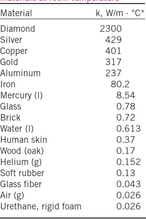
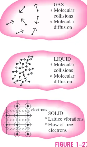
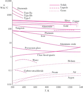
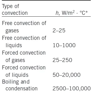
he science of thermodynamics deals with the amountof heat transfer as a system undergoes a process from one equilibrium state to another, and makes no reference to how longthe process will take. But in engineer-ing, we are often interested in the rateof heat transfer, which is the topic of the science of heat transfer.We start this chapter with a review of the fundamental concepts of thermo-dynamics that form the framework for heat transfer. We first present the relation of heat to other forms of energy and review the first law of thermo-dynamics. We then present the three basic mechanisms of heat transfer, which are conduction, convection, and radiation, and discuss thermal conductivity. Conductionis the transfer of energy from the more energetic particles of a substance to the adjacent, less energetic ones as a result of interactions be-tween the particles. Convectionis the mode of heat transfer between a solid surface and the adjacent liquid or gas that is in motion, and it involves the combined effects of conduction and fluid motion. Radiation is the energy emitted by matter in the form of electromagnetic waves (or photons) as a re-sult of the changes in the electronic configurations of the atoms or molecules. We close this chapter with a discussion of simultaneous heat transfer.
1
CHAPTER
1
CONTENTS1–1 Thermodynamics and Heat Transfer 2
1–2 Engineering Heat Transfer 4
1–3 Heat and Other Forms of Energy 6
1–4 The First Law of Thermodynamics 11
1–5 Heat Transfer Mechanisms 17
1–6 Conduction 17
1–7 Convection 25
1–8 Radiation 27
1–9 Simultaneous Heat Transfer
Mechanism 30
1–10 Problem-Solving Technique 35
1–1
THERMODYNAMICS AND HEAT TRANSFER
We all know from experience that a cold canned drink left in a room warms up and a warm canned drink left in a refrigerator cools down. This is accom-plished by the transfer of energyfrom the warm medium to the cold one. The energy transfer is always from the higher temperature medium to the lower temperature one, and the energy transfer stops when the two mediums reach the same temperature.
You will recall from thermodynamics that energy exists in various forms. In this text we are primarily interested in heat,which is the form of energy that can be transferred from one system to another as a result of temperature dif-ference.The science that deals with the determination of the ratesof such en-ergy transfers is heat transfer.
You may be wondering why we need to undertake a detailed study on heat transfer. After all, we can determine the amount of heat transfer for any sys-tem undergoing any process using a thermodynamic analysis alone. The rea-son is that thermodynamics is concerned with the amountof heat transfer as a system undergoes a process from one equilibrium state to another, and it gives no indication about how longthe process will take. A thermodynamic analysis simply tells us how much heat must be transferred to realize a specified change of state to satisfy the conservation of energy principle.
In practice we are more concerned about the rate of heat transfer (heat trans-fer per unit time) than we are with the amount of it. For example, we can de-termine the amount of heat transferred from a thermos bottle as the hot coffee inside cools from 90°C to 80°C by a thermodynamic analysis alone. But a typ-ical user or designer of a thermos is primarily interested in how longit will be before the hot coffee inside cools to 80°C, and a thermodynamic analysis can-not answer this question. Determining the rates of heat transfer to or from a system and thus the times of cooling or heating, as well as the variation of the temperature, is the subject of heat transfer(Fig. 1–1).
Thermodynamics deals with equilibrium states and changes from one equi-librium state to another. Heat transfer, on the other hand, deals with systems that lack thermal equilibrium, and thus it is a nonequilibriumphenomenon. Therefore, the study of heat transfer cannot be based on the principles of thermodynamics alone. However, the laws of thermodynamics lay the frame-work for the science of heat transfer. The first lawrequires that the rate of energy transfer into a system be equal to the rate of increase of the energy of that system. The second lawrequires that heat be transferred in the direction of decreasing temperature (Fig. 1–2). This is like a car parked on an inclined road that must go downhill in the direction of decreasing elevation when its brakes are released. It is also analogous to the electric current flowing in the direction of decreasing voltage or the fluid flowing in the direction of de-creasing total pressure.
The basic requirement for heat transfer is the presence of a temperature dif-ference.There can be no net heat transfer between two mediums that are at the same temperature. The temperature difference is the driving forcefor heat transfer, just as the voltage differenceis the driving force for electric current flow and pressure differenceis the driving force for fluid flow. The rate of heat transfer in a certain direction depends on the magnitude of the temperature gradient(the temperature difference per unit length or the rate of change of
■
Hot coffee Thermos
bottle
Insulation FIGURE 1–1
We are normally interested in how long it takes for the hot coffee in a thermos to cool to a certain temperature, which cannot be determined from a thermodynamic analysis alone.
Heat
Cool environment
20°C Hot
coffee 70°C
FIGURE 1–2
temperature) in that direction. The larger the temperature gradient, the higher the rate of heat transfer.
Application Areas of Heat Transfer
Heat transfer is commonly encountered in engineering systems and other as-pects of life, and one does not need to go very far to see some application ar-eas of heat transfer. In fact, one does not need to go anywhere. The human body is constantly rejecting heat to its surroundings, and human comfort is closely tied to the rate of this heat rejection. We try to control this heat trans-fer rate by adjusting our clothing to the environmental conditions.
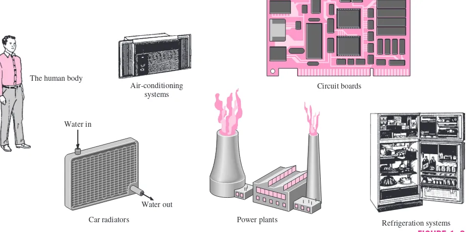
Many ordinary household appliances are designed, in whole or in part, by using the principles of heat transfer. Some examples include the electric or gas range, the heating and air-conditioning system, the refrigerator and freezer, the water heater, the iron, and even the computer, the TV, and the VCR. Of course, energy-efficient homes are designed on the basis of minimizing heat loss in winter and heat gain in summer. Heat transfer plays a major role in the design of many other devices, such as car radiators, solar collectors, various compo-nents of power plants, and even spacecraft. The optimal insulation thickness in the walls and roofs of the houses, on hot water or steam pipes, or on water heaters is again determined on the basis of a heat transfer analysis with eco-nomic consideration (Fig. 1–3).
Historical Background
Heat has always been perceived to be something that produces in us a sensa-tion of warmth, and one would think that the nature of heat is one of the first things understood by mankind. But it was only in the middle of the nineteenth
FIGURE 1–3 Some application areas of heat transfer.
Refrigeration systems Power plants
Car radiators
Water out Water in
Circuit boards Air-conditioning
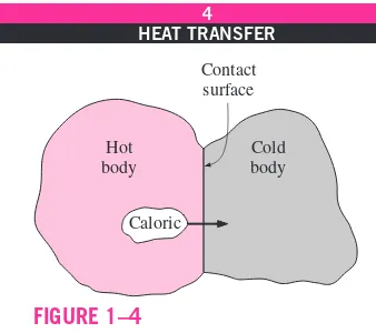
century that we had a true physical understanding of the nature of heat, thanks to the development at that time of the kinetic theory,which treats molecules as tiny balls that are in motion and thus possess kinetic energy. Heat is then defined as the energy associated with the random motion of atoms and mole-cules. Although it was suggested in the eighteenth and early nineteenth cen-turies that heat is the manifestation of motion at the molecular level (called the live force), the prevailing view of heat until the middle of the nineteenth cen-tury was based on the caloric theoryproposed by the French chemist Antoine Lavoisier (1743–1794) in 1789. The caloric theory asserts that heat is a fluid-like substance called the caloricthat is a massless, colorless, odorless, and tasteless substance that can be poured from one body into another (Fig. 1–4). When caloric was added to a body, its temperature increased; and when caloric was removed from a body, its temperature decreased. When a body could not contain any more caloric, much the same way as when a glass of water could not dissolve any more salt or sugar, the body was said to be satu-rated with caloric. This interpretation gave rise to the terms saturated liquid and saturated vaporthat are still in use today.
The caloric theory came under attack soon after its introduction. It main-tained that heat is a substance that could not be created or destroyed. Yet it was known that heat can be generated indefinitely by rubbing one’s hands to-gether or rubbing two pieces of wood toto-gether. In 1798, the American Ben-jamin Thompson (Count Rumford) (1753–1814) showed in his papers that heat can be generated continuously through friction. The validity of the caloric theory was also challenged by several others. But it was the careful experi-ments of the Englishman James P. Joule (1818–1889) published in 1843 that finally convinced the skeptics that heat was not a substance after all, and thus put the caloric theory to rest. Although the caloric theory was totally aban-doned in the middle of the nineteenth century, it contributed greatly to the de-velopment of thermodynamics and heat transfer.
1–2
ENGINEERING HEAT TRANSFER
Heat transfer equipment such as heat exchangers, boilers, condensers, radia-tors, heaters, furnaces, refrigeraradia-tors, and solar collectors are designed pri-marily on the basis of heat transfer analysis. The heat transfer problems encountered in practice can be considered in two groups: (1) rating and (2)sizingproblems. The rating problems deal with the determination of the heat transfer rate for an existing system at a specified temperature difference. The sizing problems deal with the determination of the size of a system in order to transfer heat at a specified rate for a specified temperature difference. A heat transfer process or equipment can be studied either experimentally (testing and taking measurements) or analytically (by analysis or calcula-tions). The experimental approach has the advantage that we deal with the actual physical system, and the desired quantity is determined by measure-ment, within the limits of experimental error. However, this approach is ex-pensive, time-consuming, and often impractical. Besides, the system we are analyzing may not even exist. For example, the size of a heating system of a building must usually be determined before the building is actually built on the basis of the dimensions and specifications given. The analytical ap-proach (including numerical apap-proach) has the advantage that it is fast and
■ Hot
body
Cold body Contact surface
Caloric
FIGURE 1–4
inexpensive, but the results obtained are subject to the accuracy of the assumptions and idealizations made in the analysis. In heat transfer studies, often a good compromise is reached by reducing the choices to just a few by analysis, and then verifying the findings experimentally.
Modeling in Heat Transfer
The descriptions of most scientific problems involve expressions that relate the changes in some key variables to each other. Usually the smaller the increment chosen in the changing variables, the more general and accurate the description. In the limiting case of infinitesimal or differential changes in variables, we obtain differential equationsthat provide precise mathematical formulations for the physical principles and laws by representing the rates of changes as derivatives.Therefore, differential equations are used to investi-gate a wide variety of problems in sciences and engineering, including heat transfer. However, most heat transfer problems encountered in practice can be solved without resorting to differential equations and the complications asso-ciated with them.
The study of physical phenomena involves two important steps. In the first step, all the variables that affect the phenomena are identified, reasonable as-sumptions and approximations are made, and the interdependence of these variables is studied. The relevant physical laws and principles are invoked, and the problem is formulated mathematically. The equation itself is very in-structive as it shows the degree of dependence of some variables on others, and the relative importance of various terms. In the second step, the problem is solved using an appropriate approach, and the results are interpreted.
Many processes that seem to occur in nature randomly and without any or-der are, in fact, being governed by some visible or not-so-visible physical laws. Whether we notice them or not, these laws are there, governing consis-tently and predictably what seem to be ordinary events. Most of these laws are well defined and well understood by scientists. This makes it possible to pre-dict the course of an event before it actually occurs, or to study various aspects of an event mathematically without actually running expensive and time-consuming experiments. This is where the power of analysis lies. Very accu-rate results to meaningful practical problems can be obtained with relatively little effort by using a suitable and realistic mathematical model. The prepara-tion of such models requires an adequate knowledge of the natural phenomena involved and the relevant laws, as well as a sound judgment. An unrealistic model will obviously give inaccurate and thus unacceptable results.
An analyst working on an engineering problem often finds himself or her-self in a position to make a choice between a very accurate but complex model, and a simple but not-so-accurate model. The right choice depends on the situation at hand. The right choice is usually the simplest model that yields adequate results. For example, the process of baking potatoes or roasting a round chunk of beef in an oven can be studied analytically in a simple way by modeling the potato or the roast as a spherical solid ball that has the properties of water (Fig. 1–5). The model is quite simple, but the results obtained are suf-ficiently accurate for most practical purposes. As another example, when we analyze the heat losses from a building in order to select the right size for a heater, we determine the heat losses under anticipated worst conditions and select a furnace that will provide sufficient heat to make up for those losses.
Oven
Ideal 175°C
Water
Potato Actual
Often we tend to choose a larger furnace in anticipation of some future ex-pansion, or just to provide a factor of safety. A very simple analysis will be ad-equate in this case.
When selecting heat transfer equipment, it is important to consider the ac-tual operating conditions. For example, when purchasing a heat exchanger that will handle hard water, we must consider that some calcium deposits will form on the heat transfer surfaces over time, causing fouling and thus a grad-ual decline in performance. The heat exchanger must be selected on the basis of operation under these adverse conditions instead of under new conditions. Preparing very accurate but complex models is usually not so difficult. But such models are not much use to an analyst if they are very difficult and time-consuming to solve. At the minimum, the model should reflect the essential features of the physical problem it represents. There are many significant reworld problems that can be analyzed with a simple model. But it should al-ways be kept in mind that the results obtained from an analysis are as accurate as the assumptions made in simplifying the problem. Therefore, the solution obtained should not be applied to situations for which the original assump-tions do not hold.
A solution that is not quite consistent with the observed nature of the prob-lem indicates that the mathematical model used is too crude. In that case, a more realistic model should be prepared by eliminating one or more of the questionable assumptions. This will result in a more complex problem that, of course, is more difficult to solve. Thus any solution to a problem should be in-terpreted within the context of its formulation.
1–3
HEAT AND OTHER FORMS OF ENERGY
Energy can exist in numerous forms such as thermal, mechanical, kinetic, po-tential, electrical, magnetic, chemical, and nuclear, and their sum constitutes the total energyE(or eon a unit mass basis) of a system. The forms of energy related to the molecular structure of a system and the degree of the molecular activity are referred to as the microscopic energy.The sum of all microscopic forms of energy is called the internal energyof a system, and is denoted by U(or uon a unit mass basis).
The international unit of energy is joule(J) or kilojoule(1 kJ 1000 J). In the English system, the unit of energy is the British thermal unit(Btu), which is defined as the energy needed to raise the temperature of 1 lbm of water at 60°F by 1°F. The magnitudes of kJ and Btu are almost identical (1 Btu 1.055056 kJ). Another well-known unit of energy is the calorie (1 cal 4.1868 J), which is defined as the energy needed to raise the temper-ature of 1 gram of water at 14.5°C by 1°C.
Internal energy may be viewed as the sum of the kinetic and potential ener-gies of the molecules. The portion of the internal energy of a system asso-ciated with the kinetic energy of the molecules is called sensible energyor sensible heat.The average velocity and the degree of activity of the mole-cules are proportional to the temperature. Thus, at higher temperatures the molecules will possess higher kinetic energy, and as a result, the system will have a higher internal energy.
The internal energy is also associated with the intermolecular forces be-tween the molecules of a system. These are the forces that bind the molecules
to each other, and, as one would expect, they are strongest in solids and weak-est in gases. If sufficient energy is added to the molecules of a solid or liquid, they will overcome these molecular forces and simply break away, turning the system to a gas. This is a phase changeprocess and because of this added en-ergy, a system in the gas phase is at a higher internal energy level than it is in the solid or the liquid phase. The internal energy associated with the phase of a system is called latent energyor latent heat.
The changes mentioned above can occur without a change in the chemical composition of a system. Most heat transfer problems fall into this category, and one does not need to pay any attention to the forces binding the atoms in a molecule together. The internal energy associated with the atomic bonds in a molecule is called chemical(or bond) energy,whereas the internal energy associated with the bonds within the nucleus of the atom itself is called nu-clear energy.The chemical and nuclear energies are absorbed or released dur-ing chemical or nuclear reactions, respectively.
In the analysis of systems that involve fluid flow, we frequently encounter the combination of properties uand Pv.For the sake of simplicity and conve-nience, this combination is defined as enthalpyh.That is, huPvwhere the term Pvrepresents the flow energyof the fluid (also called the flow work), which is the energy needed to push a fluid and to maintain flow. In the energy analysis of flowing fluids, it is convenient to treat the flow energy as part of the energy of the fluid and to represent the microscopic energy of a fluid stream by enthalpy h(Fig. 1–6).
Specific Heats of Gases, Liquids, and Solids
You may recall that an ideal gasis defined as a gas that obeys the relation
Pv RT or P RT (1-1)
where Pis the absolute pressure, vis the specific volume, Tis the absolute temperature, is the density, and Ris the gas constant. It has been experi-mentally observed that the ideal gas relation given above closely approxi-mates the P-v-Tbehavior of real gases at low densities. At low pressures and high temperatures, the density of a gas decreases and the gas behaves like an ideal gas. In the range of practical interest, many familiar gases such as air, nitrogen, oxygen, hydrogen, helium, argon, neon, and krypton and even heav-ier gases such as carbon dioxide can be treated as ideal gases with negligible error (often less than one percent). Dense gases such as water vapor in steam power plants and refrigerant vapor in refrigerators, however, should not always be treated as ideal gases since they usually exist at a state near saturation.
You may also recall that specific heatis defined as the energy required to raise the temperature of a unit mass of a substance by one degree(Fig. 1–7). In general, this energy depends on how the process is executed. In thermo-dynamics, we are interested in two kinds of specific heats: specific heat at constant volume Cvand specific heat at constant pressure Cp. The specific
heat at constant volumeCvcan be viewed as the energy required to raise the
temperature of a unit mass of a substance by one degree as the volume is held constant. The energy required to do the same as the pressure is held constant is the specific heat at constant pressureCp. The specific heat at constant
Stationary fluid
Energy = h
Energy = u Flowing
fluid
FIGURE 1–6 The internal energy urepresents the mi-croscopic energy of a nonflowing fluid, whereas enthalpy hrepresents the micro-scopic energy of a flowing fluid.
5 kJ m = 1 kg
∆T = 1°C Specific heat = 5 kJ/kg·°C
pressure Cpis greater than Cvbecause at constant pressure the system is
al-lowed to expand and the energy for this expansion work must also be supplied to the system. For ideal gases, these two specific heats are related to each other by CpCvR.
A common unit for specific heats is kJ/kg · °C or kJ/kg · K. Notice that these two units are identicalsince
∆
T(°C)∆
T(K), and 1°C change in temperature is equivalent to a change of 1 K. Also,1 kJ/kg · °C ⬅1 J/g · °C ⬅1 kJ/kg · K ⬅1 J/g · K
The specific heats of a substance, in general, depend on two independent properties such as temperature and pressure. For an ideal gas, however, they depend on temperature only (Fig. 1–8). At low pressures all real gases ap-proach ideal gas behavior, and therefore their specific heats depend on tem-perature only.
The differential changes in the internal energy uand enthalpy hof an ideal gas can be expressed in terms of the specific heats as
duCvdT and dhCpdT (1-2)
The finite changes in the internal energy and enthalpy of an ideal gas during a process can be expressed approximately by using specific heat values at the average temperature as
uCv, aveT and hCp, aveT (J/g) (1-3) or
UmCv, aveT and HmCp, aveT (J) (1-4) where mis the mass of the system.
A substance whose specific volume (or density) does not change with tem-perature or pressure is called an incompressible substance.The specific vol-umes of solids and liquids essentially remain constant during a process, and thus they can be approximated as incompressible substances without sacrific-ing much in accuracy.
The constant-volume and constant-pressure specific heats are identical for incompressible substances (Fig. 1–9). Therefore, for solids and liquids the subscripts on Cvand Cpcan be dropped and both specific heats can be
rep-resented by a single symbol, C.That is, Cp艑Cv艑C.This result could also
be deduced from the physical definitions of volume and constant-pressure specific heats. Specific heats of several common gases, liquids, and solids are given in the Appendix.
The specific heats of incompressible substances depend on temperature only. Therefore, the change in the internal energy of solids and liquids can be expressed as
UmCaveT (J) (1-5)
0.718 kJ 0.855 kJ
Air m = 1 kg 300 → 301 K
Air m = 1 kg 1000 → 1001 K
FIGURE 1–8
The specific heat of a substance changes with temperature.
IRON 25°C = Cv = Cp = 0.45 kJ/kg·°C C
FIGURE 1–9
The Cvand Cpvalues of incompressible
where Caveis the average specific heat evaluated at the average temperature.
Note that the internal energy change of the systems that remain in a single phase (liquid, solid, or gas) during the process can be determined very easily using average specific heats.
Energy Transfer
Energy can be transferred to or from a given mass by two mechanisms: heat Qand work W.An energy interaction is heat transfer if its driving force is a temperature difference. Otherwise, it is work. A rising piston, a rotating shaft, and an electrical wire crossing the system boundaries are all associated with work interactions. Work done per unit timeis called power,and is denoted byW·.The unit of power is W or hp (1 hp 746 W). Car engines and hy-draulic, steam, and gas turbines produce work; compressors, pumps, and mixers consume work. Notice that the energy of a system decreases as it does work, and increases as work is done on it.
In daily life, we frequently refer to the sensible and latent forms of internal energy as heat,and we talk about the heat content of bodies (Fig. 1–10). In thermodynamics, however, those forms of energy are usually referred to as thermal energyto prevent any confusion with heat transfer.
The term heatand the associated phrases such as heat flow, heat addition, heat rejection, heat absorption, heat gain, heat loss, heat storage, heat gener-ation, electrical heating, latent heat, body heat, and heat sourceare in com-mon use today, and the attempt to replace heatin these phrases by thermal energyhad only limited success. These phrases are deeply rooted in our vo-cabulary and they are used by both the ordinary people and scientists without causing any misunderstanding. For example, the phrase body heatis under-stood to mean the thermal energy contentof a body. Likewise, heat flowis understood to mean the transfer of thermal energy, not the flow of a fluid-like substance called heat, although the latter incorrect interpretation, based on the caloric theory, is the origin of this phrase. Also, the transfer of heat into a sys-tem is frequently referred to as heat additionand the transfer of heat out of a system as heat rejection.
Keeping in line with current practice, we will refer to the thermal energy as heatand the transfer of thermal energy as heat transfer.The amount of heat transferred during the process is denoted by Q.The amount of heat transferred per unit time is called heat transfer rate,and is denoted by Q·.The overdot stands for the time derivative, or “per unit time.” The heat transfer rate Q· has the unit J/s, which is equivalent to W.
When the rateof heat transfer Q· is available, then the total amount of heat transfer Qduring a time interval tcan be determined from
Q Q·dt (J) (1-6)
provided that the variation of Q· with time is known. For the special case of Q· constant, the equation above reduces to
QQ·t (J) (1-7)
冕
t 0Vapor 80°C
Liquid
80°C 25°C
Heat transfer