A MOBILE PLATAFORM WITH A CATADIOPTRIC SENSOR
A. M. G. Tommaselli a *, J. Marcato Juniorb, A. L. Olivetec and M. V. A. de Moraes a
a
Department of Cartography, Univ Estadual Paulista - Unesp, Rua Roberto Simonsen, 305, 19060-900, Pres. Prudente, S.P., Brazil; [email protected], [email protected]
b
Faculdade de Engenharia, Arquitetura e Urbanismo e Geografia – FAENG, Univ. Federal de Mato Grosso do Sul - UFMS, 79070-900, Campo Grande, M.S., Brazil - [email protected]
c
IFSP - Instituto Federal de Educação, Ciência e Tecnologia de São Paulo, Rua José Ramos Júnior, 27-50, 19470-000, Presidente Epitácio – S.P. Brazil - [email protected]
Commission I, ICWG I/Va
KEY WORDS: Mobile, Mapping, Modelling, Orientation, Sensor
ABSTRACT:
The aim of this paper is to present a mobile catadioptric omnidirectional vision system composed of a camera and a cone-shaped mirror integrated with a direct georeferencing system. The relationship between image and object space is established with generic/empiric or physical models. The models were implemented and tested with real data and some results are presented. The results showed that accuracies around 5 cm in planimetry can be achieved, which is suitable for several applications, including the generation of control scenes that was the original motivation of this work.
1. INTRODUCTION
Panoramic cameras have gained attention in Photogrammetry and Computer Vision due to their extended field of view, which makes feasible recording larger area extents, when compared to conventional perspective cameras. Several mobile systems have used cameras of this type in several applications, but mainly in urban areas (Van Den Heuvel et al., 2006). Many imaging devices have been developed to achieve wide field of view depending on the application.
This work has been driven by the generation of high resolution ground control chips aiming at indirect orientation of orbital images. The use of control chips was originally proposed by Malmström (1986) and it inspired a technique in which Terrestrial Control Chips were acquired by a fisheye lens camera (Tommaselli et al., 2013; Berveglieri and Tommaselli, 2014). Orientation of orbital images, mainly those with medium resolution, requires a more efficient technique for collecting ground information. Linear features, like roads, can be a suitable source of ground control, as it was demonstrated by Tommaselli and Marcato Junior (2012) and other authors (Habib et al., 2002; Zhang et al., 2004; Shin et al., 2007).
When using control linear features, it is required to define two endpoints and it is not productive to perform this operation with static surveying. Using a mobile georeferenced imaging system can solve some of those drawbacks, because georeferenced images can be used to locate endpoints or to generate control chips which can be automatically matched with the orbital image.
The aim of this paper is to present a mobile catadioptric omnidirectional vision system composed of a camera and a cone-shaped mirror with direct georeferencing system (double frequency GNSS receiver and IMU), the photogrammetric modelling alternatives and some results with real data.
2. BACKGROUND
Several systems aiming at the generation of omnidirectional images have been developed, with multiple cameras, rotating heads, fisheye lenses and catadioptric optics (Sturm et al., 2010).
Catadioptric systems combine refractive and reflective optical elements and are used in several imaging systems such as telescopes, microscopes and telephoto cameras.
Sturm et al. (2010) categorized existing catadioptric systems in five classes: (1) single mirror central systems, with a single effective viewpoint; (2) central systems using multiple mirrors; (3) non-central systems; (4) single lens stereo systems; and (5) programmable devices. The first class comprises those systems with a central perspective camera and a mirror surface built with a revolving conic about an axis of symmetry. Moreover, the external nodal point of the camera has to coincide with the mirror focus. These mirrored surfaces can be hyperboloidal, paraboloidal, ellipsoidal, cone-shaped or planar (Sturm et al., 2010). Coincidence of the camera´s nodal point with the cone´s tip is quite difficult to achieve, except if the cone is cut off (Lin and Bajcsy, 2001), but this reduces illuminance and causes focusing problems (Spacek, 2005). When this condition is not achieved, then infinite viewpoints exist and proper modelling is required.
Spacek (2005) proposed a practical solution for the problem of multiple viewpoints, avoiding the problems with the existing approaches. Spacek (2005) placed the cone tip at a distance d from the camera lenses in such a way that focusing and illumination were improved. In this case, the conic mirror aperture angle is 90 degrees.
Due to the advantages of cone-shaped mirrors in comparison to other catadioptric system (Spacek, 2005), the catadioptric omnidirectional sensor developed in this work uses this type of The International Archives of the Photogrammetry, Remote Sensing and Spatial Information Sciences, Volume XL-1, 2014
solution. Modeling the transformations from image coordinates to object space coordinates in this kind of systems can be done with several distinct approaches. It is well known that classic perspective projection (e.g., with collinearity equations) are unsuitable to model fisheye lens camera or catadioptric systems. Depending on the applications, generalized (or generic) models can be used to "unwrap" the omnidirectional images, but, in some cases, rigorous approaches are needed.
Generalized models avoid the development of rigorous model, in which parameters with physical meaning have to be identified, but they require a grid of Ground Control Points (GCPs) well distributed over the camera field of view. Luber and Reulke (2010) presented a study with a polynomial-based generic model and performed several experiments with different fisheye lens camera and omnidirectional catadioptric systems with central projection. The basic concept behind these generic models is to transform Cartesian coordinates to polar coordinates and to model the variations in the radius with polynomials or ratio of polynomials, as it was also presented by Kanala and Brandt (2006) and Sturm et al (2010). Some of these models also assume that angles with vertices in the nadir point are true angles, the same concept used in the origins of Photogrammetry for radial triangulation. In the approach proposed by Kanala and Brandt (2006), also assessed by Luber and Reulke (2010), a polynomial with odd powers is defined relating the θ angles with the corresponding radial distances in the image. angle between the camera z axis and the incoming ray, and these elements are related to image coordinates by Eq. (2).
( )
⎥Rigorous models establish the relationship from object to image space by means of parameters with physical meaning. In the case of catadioptric systems, modelling can be done considering a perspective camera to which a reflective device was attached. Some of these models introduce some simplifications, usually that the mirror and the camera axis are perfectly aligned (Yagi et al., 1994; Joung and Cho, 1998; Lin and Bajcsy, 2001; Spacek, 2003; Burbridge and Spacek, 2006; López-Nicolás and Sagues, 2010), which is a condition difficult to achieve in practice. Also, modelling non-central catadioptric systems requires more complex projection equations, when compared to central projection.
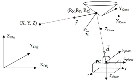
Burbridge et al. (2008) developed rigorous models (forward and backward image projections) in which the need for alignment of the cone-shaped mirror and the camera axis can be neglected. The development of this model starts with the definition of a 3D Cartesian reference system for the cone-shaped mirror, besides the conventional camera/photogrammetric and object/global, as can be seen in Figure 1. The forward modelling starts with the definition of the projecting ray (d) which is then transformed to the cone reference system by a rigid body transformation.
Figure 1: Coordinate reference systems of the omnidirectional catadioptric system.
⎥
the principal point and δx, δy corrections of the lens distortion and other systematic effects, with the other well-known elements depicted in Fig. 1.
The point of intersection (R=(RX, RY, RZ)T) of the projecting ray
and the cone surface can then be found:
c p C
R= + .r (4)
in which C are the coordinates of the camera perspective centre with respect to the cone reference system and p is a scale factor defined for each image point by introducing the cone equation (5) and replacing (4) in this equation.
0
Having the reflection point the reflected ray r is computed by equation (6) as defined by Burbridge et al. (2008).
n
in which n is the vector normal to the cone surface, defined by equation (7).In order to define the backward model three constraints are applied: (1) the reflection point lies on the cone surface; (2) the angle between the normal and the ray coming from the point in the object space must be equal to the angle between the projecting ray and the normal (3) the camera perspective centre, the reflection point, the point in the object space and the normal vector all lie on the same plane. These constraints can also be derived from the well known law of reflection. These constraints generate a system of equations from which the reflection point coordinates are estimated (Burbridge et al., 2008). These authors performed some experiments with The International Archives of the Photogrammetry, Remote Sensing and Spatial Information Sciences, Volume XL-1, 2014
synthetic data to validate those models, but no further suggestions were given on the system calibration.
3. MOBILE CATADIOPTRIC OMNIDIRECTIONAL SYSTEM
The main aim of the system being developed was the generation of high resolution georeferenced image chips, with a mobile catadioptric unit, to be used as control entities for orbital images orientation. Considering this application, the imaging sensor should acquire images in a certain field of view to encompass significant features around the moving vehicle and that should be identified in the orbital images.
After some empirical investigation, it was realized that a catadioptric system should be suitable. Existing systems, however, did not fulfil the project’s needs, mainly due to the required features regarding extended field o view and camera exposure time. It was necessary to use a Reflex camera with a wide angle lens and to build a large metallic cone-shaped mirror.
Camera Fuji Finepix S3Pro(12.1 Mpixel) Lens Bower-Samyang Focal length 8 mm
Cone height 38.84 mm Cone Radius 101.45 mm Camera nodal point to
mirror tip
44.28 mm
Table 1: Camera and cone-shaped mirror technical features.
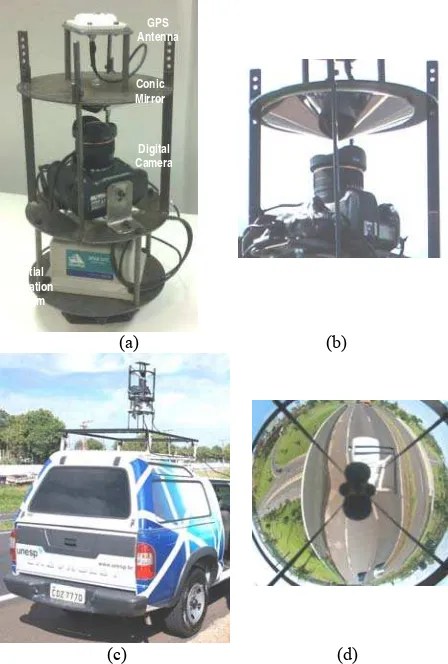
The catadioptric unit is depicted in Fig. 2.a and a side view of the conic mirror is presented in Fig. 2.b. The technical features of the camera and mirror are presented in Table 1. The camera and the cone-shaped mirror are assembled in an adjustable metallic frame along with the GNSS antenna on its top and the Novatel SPAN-CPT Inertial Navigation System below the camera mount. The camera and the mirror can be moved manually to achieve an intermediate alignment, but it can be seen that accurate alignment is not feasible, and this problem has to be considered in the system modelling. Lever arm can be directly measured and boresight misalignment angles are to be estimated in the platform system calibration process.
The system mounted over a vehicle is shown in Fig. 2.c and an example of an image acquired over a road is presented in Fig. 2.d. Besides the external unit, a control computer and a power unit are carried in the vehicle. The control computer triggers the camera which sends a pulse to the SPAN-CPT unit, which in turn, grabs this time along with GNSS and IMU data. Manual triggering is also allowed. GNSS and IMU data are processed with Inertial Explorer (WayPoint Consulting) software.
The acquired images have a distorted geometry (see Figure 2.d) and special mathematical models are required for the calibration, orientation and rectification.
Two sets of approaches have been studied within the research group: empirical-generalized and rigorous-physical modelling. The first group of techniques requires a very dense network of control points to estimate parameters of polynomial-like models. Some empirical-generalized models which were implemented and tested are RPC (Rational Polynomial Coefficients) and (φ-r) polynomials (Olivete, 2014).
INS
Figure 2: a) Catadioptric system; b) side view of the cone-shaped mirror; c) Mobile System and, d) example of an image acquired over a road.
A ratio of 2D Polynomials, relating planimetric coordinates of points in the object space and image columns and rows (cn rn)
were used, because the main aim was to generate aerial views from approximately flat areas.
cn=
The coefficients of Equations (8) can be estimated with Least Squares, provided that a suitable number and well distributed pairs of object and image coordinates are acquired.
A second group of generalized models, which are variants of the polynomial method, were implemented and tested. Basically, given a control point, from its X and Y coordinates in a local system with origin at the camera station, polar coordinates (Φ, R) and (φ, r) in the object and image space, respectively, are computed (Eq. 9) and from corresponding points in the image, the coefficients of a polynomial (Eq. 10), describing the changes in the radial distance, can be estimated.
2 The International Archives of the Photogrammetry, Remote Sensing and Spatial Information Sciences, Volume XL-1, 2014
In which cnand rn are image coordinates with origin in the
image centre)
Since the camera position is known from GNSS positioning, this technique is quite straightforward. However, misalignment between the mirror and the camera causes asymmetry in the R values. To cope with this asymmetric effect another polynomial is used to relate the horizontal angles in the object and image space and, finally, a model based on sin function absorbs the remaining systematic effects (Olivete, 2014).
The second approach relies on rigorous modelling of the physical components of the system (Marcato Jr, 2014). In this system a camera with wide angle/fisheye lenses points upward to a conic mirror. The developed approach for rigorous modelling requires several intermediate steps:
(1) camera calibration: this task was performed with existing 3D calibration field and software to which models for fisheye lens (equidistant with Conrady-Brown distortion coefficients) was included (Tommaselli et al., 2014);
(2) Conic mirror modelling: this task was carried out by photogrammetric bundle adjustment. Several targets were painted over the cone surface and a set of convergent images were taken with the cone positioned over a set of known targets. The 3D coordinates of the targets along with the EOPs (Exterior Orientation Parameters) and IOPs (Inner Orientation Parameters) were estimated with on-the-job camera calibration with bundle adjustment. Using these 3D coordinates as observations the parametric model of the cone was estimated by Least Squares Adjustment, obtaining residuals with RMSE of 0.2 mm;
(3) Rigid body transformation from cone to camera system: Some reference points in the cone base were used to compute these parameters;
(4) Projection of the image coordinates to the conic mirror surface: for each image point the 3D coordinates of the reflection point are computed with inverse collinearity equations, having the cone model as the surface of intersection;
(5) Cone to object space projection: The components of the reflected ray vector are estimated with Eq. (6).
The system was mounted over a vehicle, as shown in Fig. 2.c and some images over open areas in roads and streets were acquired and some of them were selected for the practical experiments. The models were implemented in C++ and Matlab using existing libraries.
4. EXPERIMENTS AND RESULTS
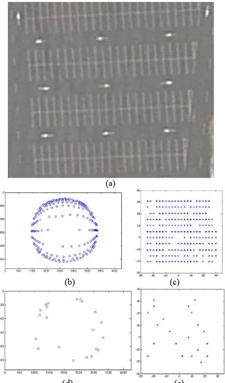
In order to assess the proposed modelling strategies, preliminary experiments with real data were performed. A large parking area was used, over which road marks were used as distinguishable targets (Fig. 3.a). The coordinates of some targets where measured with GNSS surveying and with direct techniques, resulting in a total of 210 planimetric control points and 21 check points.
(a)
(b) (c)
(d) (e)
Figure 3: a) Aerial view of the test area; b) GCPs measured in the image; c) GCPs in the object space; (d) Check points measured in the image; e) Check points in the object space.
Parameters of three different generic models were estimated and the residuals after projecting from the object to the image space were computed. RFM (Eq. 8) with 3rd and 4rd order polynomials and adjustment with φ-r polynomials (POL) were used. The residuals of these methods are plotted against the radius in Figures 4.a, 4.b and 4.c, respectively. The standard deviations of the residuals in the GCPs and in the Check Points are presented in Table 2.
It can be seen from the residuals plot that both RFM models have greater dispersion (Fig. 4.a, 4.b), when compared to the
φ-r polynomial Model (Fig. 4.c). The residuals of this model are clearly higher in a specific range of distances (120 pels) where some outliers can be seen, probably due to some imperfections in the mirror construction.
(a)
(b)
(c)
(d)
(e)
Figure 4: Residuals with radial distance for: a) RFM with 3rd order polynomials; b) RFM with 4rd order polynomials; c) Adjustment with φ-r polynomials. d) Example of a omnidirectional image, and; e) an image resampled with φ-r polynomials
Comparing the residuals plot with Table 2, it can be concluded that the best fit was achieved with the φ-r polynomial model. The standard deviation of the residuals in the check points were equivalent to that obtained with RFM with 4rd polynomials, but it is clear from Fig. 4.b and 4.c that the best fit was achieved with this polynomials.
Model
σRESIDUALS GCPs (pixels)
σRESIDUALS Check Points
(pixels) RFM - 3rd order polynomials 18 17 RFM - 4rd order polynomials 13 9 Adjustment - φ-r polynomials 9 9.6
Table 2: The standard deviations of the residuals in the Ground Control Points and in the Check Points.
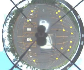
Some preliminary experiments were also performed with the rigorous model, outlined in section 3. The same test area was used, with 24 GCPs, determined with RTK surveying with an estimated precision of 1.5 cm in XY and 2.5 cm in height. The modelling process, as presented in section 3, was applied and a RMSE of 0.2 mm was achieved in the residuals of the cone fitting. Considering that, a standard deviation of 0.3 mm was used for the coordinates of the reflection points. The transformation parameters from the camera to the cone reference system were previously determined in an accurate calibration field. Then, the transformation parameters of the cone to the object space were indirectly estimated with Least Squares adjustment, based on the GCPs coordinates and corresponding image coordinates, interactively measured. These parameters can be assumed as the EOPs of the system. Figure 5 shows one of the omnidirectional images used in this experiment, in which the GCPs were highlighted. Table 3 presents the standard deviations of the transformation from the cone to the object space reference systems.
Figure 5: Omnidirectional image of the test area with GCP highlighted.
Obj Cone ω
(º)
Obj Cone
ϕ (º)
Obj Cone
κ
(º)
XV (m)
YV (m)
ZV (m)
0.0473 0.0594 0.0886 0.031 0.032 0.010
0
ˆ
σ
= 1.07Table 3: Estimated standard deviations of the transformation parameters from the cone to the object space and the sigma naught.
Using these parameters the expected accuracy of ground coordinates around the GCPs are around 5 cm in XY and 10 cm in height, which is acceptable not only for the generation of control scenes but for several other applications of Mobile Mapping Systems.
5. CONCLUSIONS
An omnidirectional catadioptric unit for Mobile Mapping has been developed and some features of this system along with preliminary experiments were present in this paper.
A wide-angle digital camera was connected to a cone-shaped mirror and an Inertial Navigation System, being feasible to acquire georeferenced panoramic images with a single shot. Modelling this kind of system can be done by generic/empiric or rigorous approaches and both strategies were implemented and tested.
From the experiments presented it can be concluded that with a dense control points network the empirical models provided acceptable results, although some imperfections could be identified due to the irregularities in mirror manufacturing and model simplifications.
Rigorous modelling achieved also accurate results with discrepancies around 5 cm in the object space for points close to the system, and with less GCPs.
The acquired images can be used in several applications, such as generation of control templates, generation of panoramas, identification and location of road sign and many others.
ACKNOWLEDGEMENTS
The authors would like to acknowledge the CNPQ (Conselho Nacional de Desenvolvimento Científico e Tecnológico - grant 477738/2009-5), and FAPESP (Fundação de Amparo à Pesquisa do Estado de São Paulo – grants: 2010/16954-5; 2010/16439-3) for financial support.
REFERENCES
Berveglieri, A. and Tommaselli, A. M. G., 2014. Multi-scale matching for the automatic location of control points in large scale aerial images using terrestrial scenes. In: Int. Arch. Photogramm. Remote Sens. Spatial Inf. Sci., CastelDefels, Spain, XL-3/W1, pp. 27-31.
Burbridge, C. and Spacek, L., 2006. Omnidirectional vision simulation and robot localisation. In: Proceedings of TAROS
2006, pp.32- 39.
Burbridge, C.; Nehmzow, U.; Condell, J., 2008. Omnidirectional Projections with Cone Mirror and Single Mirror Stereo. In: The 8th Workshop on Omnidirectional Vision, Camera Networks and Non-classical Cameras.
Habib, A, Morgan, M. and Lee, Y., 2002. Bundle Adjustment with Self-Calibration using Straight Lines. Photogrammetric Record, 17(100): 635–650.
Joung, I. S.; Cho. H. S., 1998. An active omni-directional range sensor for mobile robot navigation.Control Engineering Practice, v. 6, pp. 385-393.
Kannala, J., Brandt S., 2006. A Generic Camera Model and Calibration Method for Conventional, Wide-Angle, and FishEye Lenses. IEEE Transactions on Pattern Analysis and Machine Intelligence, 28(8), pp. 1335-1340.
Lin, S. S., and Bajcsy, R., 2001. True single view point cone mirror omnidirectional catadioptric system. In: Proceedings of the IEEE International Conference on Computer Vision, pp. 102–107.
López-Nicolás, G.; Sagüés, C., 2010. Catadioptric camera model with conic mirror. In: Proceedings of the British Machine Vision Conference, Aberystwyth, UK, pp. 114.1-114.10.
Luber, A., And Reulke, R, 2010. A unified calibration approach for generic cameras. In: The International Archives of the Photogrammetry, Remote Sensing and Spatial Information Sciences. Newcastle upon Tyne, UK. XXXVIII (B5), pp. 399-404.
Malmström, H., 1986. Measuring ground control points for satellite image rectification. In: Schriftenreihe Des Instituts Für Photogrametrie Der Universität Stuttgart, 11, pp. 127–135.
Marcato Junior, J. 2014. Modelagem fotogramétrica e calibração de um sistema de visão omnidirecional. Doctoral Thesis. São Paulo State University, Presidente Prudente, Brazil (In portuguese).
Marcato Junior, J., Olivete, A. L., Berveglieri, A., Tommaselli, A. M.G., 2012. Photogrammetric modelling of a catadioptric omnidirectional system In: Remote Sensing and Photogrammetry Society's Annual Conference, Greenwich, UK.
Olivete, A. L., 2014. Utilização de imagens omnidirecionais georreferenciadas como controle de campo para orientação de imagens orbitais. Doctoral Thesis. São Paulo State University, Presidente Prudente, Brazil (In portuguese).
Shin, S.W., Habib, A. F., Ghanma, M., Kim, G. and Kim, E. M., 2007. Algorithms for Multi-sensor and Multi-primitive Photogrammetric Triangulation. ETRI Journal, 29(4), pp. 411– 420.
Spacek, L., 2003. Omnidirectional perspective and stereopsis with conical mirrors. Research Report CTU–CMP–2003–12, Center for Machine Perception, K13133 FEE Czech Technical University, Prague, Czech Republic.
Spacek, L., 2005. A catadioptric sensor with multiple viewpoints. Robotics and Autonomous Systems, 51 (1), pp. 3-15.
Sturm, P., Ramalingam, S., Tardif, J., Gasparini, S., and Barreto, J., 2010. Camera Models and Fundamental Concepts Used in Geometric Computer Vision. Computer Graphics and Vision, 6 (1-2), pp. 1-183.
Tommaselli, A. M. G, Marcato Junior, J., 2012. Bundle Block Adjustment of CBERS-2B HRC Imagery Combining Control Points and Lines. Photogrammetrie, Fernerkundung, Geoinformation. , v.2012, pp.129 - 139.
Tommaselli, A.M.G, Berveglieri, A., Marcato Junior, J., Olivete, A. L. On The Generation Of Ground Control Scenes with Mobile Platforms. In: International Symposium on Mobile Mapping Technology (MMT), Tainan, Taiwan.
Tommaselli, A. M. G.; Marcato Junior; Moraes, M.V.A. ; Silva, S. L. A. ; Artero, A. O. Calibration of panoramic cameras with coded targets and a 3D calibration field. In: Int. Arch. Photogramm. Remote Sens. Spatial Inf. Sci., CastelDefels, Spain, XL-3/W1, pp. 137-142.
Van Den Heuvel, F. A. et al., 2006. Calibration of fisheye camera systems and the reduction of chromatic aberration. In: In: Int. Arch. Photogramm. Remote Sens. Spatial Inf. Sci., Dresden, Germany, XXXVI(5).
Yagi, Y.; Kawoto, S.; Tsuji, S., 1994. Real time omnidirectional image sensor (COPIS) for vision-guided navigation. IEEE Trans. on Robotics and Automation, 10(1), pp. 11-22.
Zhang, J., Zhang, H., Zhang, Z., 2004. Exterior orientation for Remote Sensing image with high resolution by linear feature. In: Int. Arch. Photogramm. Remote Sens. Spatial Inf. Sci. XXXV(B3), pp. 76-79.