A UAV BASED CLOSE-RANGE RAPID AERIAL MONITORING SYSTEM FOR
EMERGENCY RESPONSES
Kyoungah Choi a, Impyeong Lee a, *
a Dept. of Geoinformatics, The University of Seoul, 90 Jeonnong-dong, Dongdaemun-gu, Seoul, Korea -
(shale, iplee)@uos.ac.kr
Commission I, WG I/V
KEY WORDS: UAV, Multi-sensor, Rapid Mapping, Real-time Georeferencing
ABSTRACT:
As the occurrences and scales of disasters and accidents have been increased due to the global warming, the terrorists’ attacks, and many other reasons, the demand for rapid responses for the emergent situations also has been thus ever-increasing. These emergency responses are required to be customized to each individual site for more effective management of the emergent situations. These requirements can be satisfied with the decisions based on the spatial changes on the target area, which should be detected immediately or in real-time. Aerial monitoring without human operators is an appropriate means because the emergency areas are usually inaccessible. Therefore, a UAV is a strong candidate as the platform for the aerial monitoring. In addition, the sensory data from the UAV system usually have higher resolution than other system because the system can operate at a lower altitude. If the transmission and processing of the data could be performed in real-time, the spatial changes of the target area can be detected with high spatial and temporal resolution by the UAV rapid mapping systems. As a result, we aim to develop a rapid aerial mapping system based on a UAV, whose key features are the effective acquisition of the sensory data, real-time transmission and processing of the data. In this paper, we will introduce the general concept of our system, including the main features, intermediate results, and explain our real-time sensory data georeferencing algorithm which is a core for prompt generation of the spatial information from the sensory data.
1. INTRODUCTION
In the recent few years, disasters and accidents, such as the large scaled earthquakes happened in Japan and New Zealand, have occurred more frequently and their damages also tend to be heavier. In these emergent situations, we have to construct a response system to minimize rapidly the damage of both human and property (Choi et al., 2008). Such a rapid response system is required to be customized to each individual site for more effective management of the emergent situations. These requirements can be satisfied with the decisions based on the spatial information on the target area, which should be detected immediately or in real-time (Choi et al., 2009). The spatial information is effectively generated using the aerial sensory data such as images, laser scanner and GPS/INS data. UAVs are strong candidates as the platform of the aerial monitoring system due to their easy accessibility of the emergency areas. In addition, UAVs allow us to acquire the sensory data with much higher resolution than conventional platforms.
The main advantage of monitoring systems based on the UAV, which can fly autonomously at low altitude, is rapid and stable acquisition of high-resolution sensory data on the emergency area where ones can hardly access. For those reasons, many studies using UAV systems have been conducted in various field such as military, environmental, agricultural and disaster applications. Murden et al. (2000) presented a blimp system equipped with cameras to monitor rangeland. They succeeded in acquiring high-resolution images and detecting fine scales changes in ecological system. Eisenbeiss (2004) gave an overview about low-cost and flexible UAV systems equipped with a camera, GPS/INS and a stabiliser, and then applied their system to record cultural heritage. As a result, they could
acquire images along the predefined path regularly and generate high-resolution orthoimages and DEM (Digital Elevation Model) from the images. Nagai et al. (2004) integrated a laser scanner, camera, GPS/INS with a mini UAV for the construction of DSM (Digital Surface Model) and detection of objects. 3D geometric information could be easily obtained by the laser scanner and the texture of the 3D objects also could be efficiently acquired by the camera. Jang et al. (2004) mounted a video camera and their own gimbal on a RC helicopter for 3D modelling ancient towers. The RC helicopter took images all the sides of the ancient objects because it could fly at low altitude with appropriate viewpoints. Furthermore, the system transmitted the video images to the ground station in real-time. Haarbrink et al. (2005) and Zhou et al. (2006) developed a UAV system which can provide directly georeferenced video images within two hours when disasters and accidents occur. Rapid response operations could be performed through the connection between the system and GIS system.
progress of developing a UAV based close-range rapid aerial monitoring system, which can transmit the sensory data to the ground in real-time and process the data automatically/promptly for the spatial information of the target areas under emergency such as orthoimages and DEM. Moreover, our system is based on highly sophisticated software rather than expensive platform and sensors. In this paper, we introduce the general concept of the system, including the main features, intermediate results from integration tests, and its potential for the emergency response systems.
2. UAV BASED CLOSE-RANGE RAPID AERIAL MONITORING SYSTEM
Our UAV based close-range rapid aerial monitoring system for emergency responses consists of two main sectors, aerial sector and ground sector. The aerial sector includes a UAV platform, sensors and supporting modules. The ground sector also consists of a ground vehicle, receiving system and processing system. Through a RF link between the both sectors, the sensory data and control commands are transmitted in real-time. The overview of our whole system is illustrated in Figure 1.
Figure 1. Overview of UAV based close-range rapid aerial monitoring system
2.1 Aerial Sector
The aerial sector acquires the sensory data and transmits the data to the ground sector in real-time. The aerial sector consists of a UAV platform equipped with different types of sensor: camera, laser scanner, GPS, IMU, and the supporting modules for sensor integration, data transmission to the ground, data storage, time synchronization and sensor stabilization.
2.1.1 UAV Platform: There are only a few requirements for the UAV platform: the autonomous flight function and maximum payload weight. With the autonomous flight, we can acquire the high-resolution sensory data regularly at low altitude along a predefined trajectory. Moreover, its maximum payload weight should be larger than the sum of the sensor system and supporting module in weight. With the consideration of the target application in disaster management, we selected Schiebel’s Camcopter S-100 as the UAV platform, which can fly stably in unsettled weather, since the weather is usually windy and rainy when the disaster occurs. The model is shown in Figure 2.
Figure 2. Schiebel’s Camcopter S-100
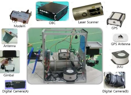
2.1.2 Sensor system: We selected small and light medium-grade sensors to pursue a flexible, light, and low cost system. Insufficient accuracy caused by the sensor will be overcome by our own sophisticated algorithm. The sensor system includes two cameras, a laser scanner, GPS and IMU. One of the two cameras acquires overview images in a nadir direction, while the other tracks detail images of a specific target being supported by a gimbal. They are illunis’ XMV-16 and
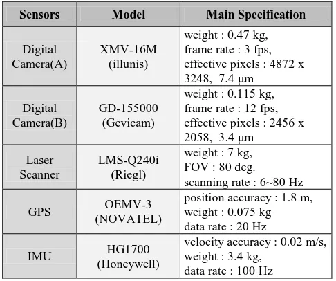
Gevicam’s GD-155000, respectively. Both are non-metric and medium format camera. The laser scanner is essential to generate DEM/DSM and orthoimages rapidly. We adopt Riegl’s LMS-Q240i, where its measurement rate and field of view are 10,000 points/second and 80 degree, respectively. GPS and IMU are also necessary to provide initial EOP (Exterior Orientation Parameters) of the image sequences and laser points. We also choose medium-grade GPS and IMU, which are Novatel’s OEMV3 and Honeywell’s HG1700. The horizontal and vertical position accuracy of the GPS is ±1.2 m and ±2.4 m, respectively. The accelerometer and gyroscope bias of the IMU is ±1 mg and ±1 deg/h, respectively. The main specifications of the sensors employed for our system listed in Table 2. All the sensors are integrated with the support modules and mounted on a rigid frame as shown in Figure 3.
Sensors Model Main Specification Table 1. Model and main specifications of the sensors
2.1.3 Supporting modules: These modules consist of an OBC (On-Board Computer), a gimbal and a power supply system. The OBC undertakes major five tasks: (1) sensor control, which control all the individual sensors according to the commands from the ground sector; (2) sensory data storage; (3) time synchronization, which tags all sensory data with GPS times; (4) image compression, which is needed to transmit the data in real-time via a RF link due to their large volume; (5) data transmission. The gimbal system is to reduce the effects of the vibration on the camera and orient the camera to a specific direction or track a particular target during a flight. This system is based on MEMS IMU and DSP so that it can be small and light enough to be mounted on a small UAV. The prototypes of the OBC and gimbal are shown in Figure 4. The power supply system includes power switches, DC-DC converters and batteries, providing the appropriate electrical power to all the sensors and modules.
Figure 4. Prototypes of the OBC and gimbal
2.2 Ground Sector
The ground sector receives the sensory data from the aerial sector in real-time and produces spatial information such as DEM and orthoimages rapidly. The ground sector is deployable and consists of a ground vehicle, a receiving and processing system. We construct the ground sector by remodelling a 2.5 ton truck as the ground vehicle and loading it with the receiving and processing system, as shown in Figure 5. The receiving system transmits the control commands and receives the data through a RF link in real-time. The processing system performs
real-time georeferencing and rapid generation of the spatial information.
Figure 5. Deployable ground station
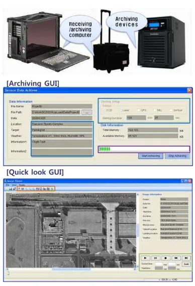
2.2.1 Receiving system: The receiving system includes a RF subsystem, a sensor control subsystem and a receiving/archiving subsystem. The RF subsystem consisting of an antenna, a modem, a GPS, and antenna tracking software, performs the real-time transmission of control commands and sensory data. Through the control subsystem, we control all the sensors remotely such as turning on/off the sensors and setting their operational parameters during the flight. The main hardware and GUI of the three subsystems are shown in Figure 6, 7, and 8. The receiving/archiving subsystem, which covers receiving, displaying and archiving the data from the aerial sector, is constructed by employing portable computers and large-capacity storage devices.
Figure 7. Sensor control subsystem
Figure 8. Receiving & archiving subsystem
2.2.2 Processing system: Through the processing system, we perform georeferencing of sensory data in real-time and produce DEM, orthoimages rapidly from the georeferenced data. The outline of the processing system is shown in Figure 9. Each subsystem will be explained briefly as follows.
For the real-time aerial monitoring, it is essential to perform georeferencing as well as transmit the sensory data in real-time. Georeferencing, which is to determine the EOP of the sensory data such as images and LiDAR (Light Detection and Range) data, should be conducted in real-time to detect the changes on
the target area quickly by comparing existing spatial information with new data acquired from our system. Besides, real-time georeferencing enable to produce the spatial information such as DEM and orthoimages rapidly from the data acquired by our system. Therefore, we develop the real-time georeferencing subsystem, where the data flows are illustrated in Figure 10. The subsystem consists of major three steps: (1) integrating GPS/IMU for PAD; (2) adjusting position/attitude information by sequential AT; and (3) georeferencing laser scanning data. First, the initial EOPs of the images are determined by applying EKF (Extended Kalman Filter) to GPS and IMU data. Second, the initial EOPs are adjusted by the image georeferencing algorithm based on the sequential AT (Aerial Triangulation) whenever a new image is acquired. Third, more accurate EOPs are used for georeferencing of the laser scanning data. Finally, we can obtain more precise georeferenced image sequences and LiDAR data from medium-grade GPS/IMU. In addition, the procedure is conducted in real-time without any GCP (Ground Control Point), which are hard to acquire in an emergent area.
Figure 7. Outline of the processing system
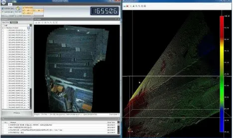
The rapid spatial information generation subsystem generates quickly rough DEM and orthoimages from georeferenced images and LiDAR data. The DEM is produced using the LiDAR data through four steps, which are outlier removal, terrain point filtering, grid creation, and interpolation. The orthoimages are then generated by orthorectifying georeferenced images using the DEM. Those products are displayed in real-time as shown in Figure 11.
Figure 9. Real-time display subsystem
3. INTEGRATION TEST & INTERMEDIATE RESULTS
We are still in progress of developing the UAV close-range rapid monitoring system. The development of individual sector is almost completed. At present, we are performing integration tests. Hence, we only present the intermediate results from the tests in this chapter.
3.1 Integration Test
The test is performed in Chungju, Korea. The test site is about 300 x 1600 m2 in area and covers residential, agricultural land and river areas as shown in Figure 12. The flight altitude and velocity are 200 m and 60 km/h, respectively.
Figure 10. Test field and flight path
3.2 Intermediate Results
As a result of the test, we acquired about 200 images, 2,000,000 laser points, 192 GPS data and 1890 IMU data. Some GPS and IMU data are omitted because the OBC is not yet stable. Since the lens has a focal length of 50 mm and the flight altitude is 200 m, the GSD (Ground Sampling Distance) of the images is about 3 cm. The point density of LiDAR data is 4.16 points/m2. The data acquisition results are summarized in Table 2; and sample images are shown in Figure 13.
Data Parameters
Image
Single Image Coverage : 145 × 95 m Ground Sampling Distance : 3 cm Overlap : 88 %
LiDAR
Density : 4.16 points/ m2 Scan width : 50 cm Scan rate : 30 lines/second
Table 2. Data acquisition results from the integration test
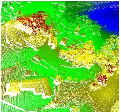
The position/attitude data from the GPS/IMU are interpolated in the data acquisition frequency and used for the initial EOPs of the images and LiDAR data. Using the images and initial EOPs without any GCP, we perform georeferencing and generate orthoimages as shown in Figure 14. The results show that the quality of the orthoimages is quite satisfactory for the emergency responses. By integrating laser scanner raw data with the initial EOPs, we produce georeferenced LiDAR data as shown in Figure 15. From these LiDAR data, we can recognize various features such as forest, buildings and other features. These data can be useful for change detection and orthoimage generation.
Figure 11. Sample images obtained from our system
Figure 13. Georeferenced LiDAR data
4. CONCLUSIONS
In this study, we introduce a UAV close-range rapid monitoring system for emergency responses. The rapid monitoring system consists of the aerial and ground sector. The aerial sector includes a UAV platform, different types of sensor and supporting modules. In the ground sector, which consists of a ground vehicle, receiving and processing system, the sensory data are processed in real-time and the spatial information such as DEM and orthoimages is generated rapidly.
We conduct integration tests for evaluating the performance of our system. During the tests, we can successfully acquire the sensory data of a test site in real-time. By processing the data, we can produce the high-quality DEM and orthoimages. The spatial information acquired by our system will be useful for many important tasks in the management of emergent situations.
ACKNOWLEDGEMENTS
This research was supported by a grant (06KLSGB01) from Cutting-edge Urban Development – a Korean Land Spatialization Research Project funded by the Ministry of Land, Transport and Maritime Affairs.
REFERENCE
Choi, K., Lee, I., Shin, S.W. and Ahn, K., 2008. A project overview for the development of a light and flexible rapid mapping system for emergency response. International Archives of Photogrammetry, Remote Sensing and Spatial Information Sciences, Vol. 37-B5, pp. 915-920.
Choi, K., Lee, I., Shin, S.W. and Park, W., 2009. Developing a UAV-based rapid mapping system for emergency response. Proceedings of SPIE Defense, Security, Sensing, Orlando, FL, USA, 2009.
Murden, S. B. and Risenhoover, K. L., 2000. A blimp system to obtain high-resolution, low-altitude aerial photography and videography. Wildlife Society Bulletin, Vol. 28, No. 4, pp.958-962.
Eisenbeiss, H., 2004. A mini unmanned aerial vehicle (UAV): system overview and image acquisition. International Archives of Photogrammetry, Remote Sensing and Spatial Information Sciences, Vol. XXXVI-8/W2, Pitsanulok, Thailand.
Nagai, M., Shibasaki, R., Manandgar, D. and Zhao, H., 2004. Development of digital surface model and feature extraction by integrating laser scanner and CCD sensor with IMU. International Archives of the Photogrammetry, Remote Sensing and Spatial Information Sciences, Vol. XXX-A,B1-B8, Istanbul, Turkey.
Jang, H., Lee, J., Kim, M., Kang, I. and Kim, C., 2004. Construction of national heritage management system using RC helicopter photogrammetric surveying system. International Archives of the Photogrammetry, Remote Sensing and Spatial Information Sciences, Vol. XXX-A,B1-B8, Istanbul, Turkey. Haarbrink, R. B. and Koers, E., 2005. Helicopter UAV for photogrammetry and rapid response. International Archives of Photogrammetry, Remote Sensing and Spatial Information Sciences, Vol. XXXVI-1/W44, Antwerp, Belgium.