2D/3D semantic annotation towards a set of spatially-oriented photographs
A. Manuel1,2, C. Stefani1, L. De Luca1 and P. Veron2
1UMR 3495 (CNRS/MCC) MAP, Ecole Nationale Supérieure d’Architecture, 184 Av. de Luminy, 13009
, Marseille, France (adeline.manuel,chiara.stefani,[email protected])
2
UMR CNRS 7296 LSIS, Ecole Nationale Supérieure d’Arts et Métiers, 2 cours des Arts et Métiers, 13617, Aix-en-Provence, France ([email protected])
KEYWORDS: Cultural heritage, photogrammetry, image-based modelling, image processing, semantic annotation
ABSTRACT:
In the domain of conservation and promotion of cultural heritage, the development of new information technologies offers new tools for sharing knowledge on heritage building. These tools are destined to help experts to enrich and access information about buildings. This article proposes an approach allowing the automatic transfer of annotations in a set of spatially-oriented photographs (whose positions and orientations in space are estimated) by using 3D information. First of all, an automated image-based 3D reconstruction method produces 3D information (specifically 3D coordinates) by processing photographs of the set. Then, the process of annotations’ transfer between images uses this generated 3D information. Finally, this process allows the implementation of the annotations modification. As a consequence, this process provides a simple way to annotate blocs of images all at once instead of one by one.
1. INTRODUCTION
In the domain of conservation and promotion of cultural heritage, the development of information technologies offers new possibilities to experts for managing large amount of data, sharing knowledge and facilitating the access to culture. These new developed tools provide a way to collect, to structure and to distribute information.
The digitisation, acquisition and 3D reconstruction methods have known significant progress in recent years. With these methods, quite precise representation of buildings can be created. For these reasons, they have become a privileged support for buildings’ documentation. However, these methods do not always satisfy all the specialists’ needs.
As documentary sources, iconographic sources (such as drawing, painting, photographs …) constitute an important value for architectural studies. These sources are very numerous and testify the state of buildings at a specific time. Among the various iconographic sources, photographs have enjoyed significant progress with the development of camera technology. Nowadays, the production of photographs is easy. Furthermore, photographs contain a high level of details in terms of colors and shapes. For these reasons, they could be considered as an ideal support for the documentation of buildings and permit to perform several analyses. Firstly, entirely or partially annotated photographs, with key-words or ontology, give sense to information contained in images. Secondly, analyses on the architectural shapes by measuring, extracting profiles, recognizing element, etc, could be directly performed on photographs. Thirdly, they testify to the state of preservation (for example, degradation phenomena) and could serve as a support for characterizing buildings’ surfaces. Finally, the generation of 3D representations can be performed from images (image-based modelling) with an identical precision as 3D models obtained from laser acquisition, thanks to the progress in photogrammetry. As a consequence, photography reveals itself as an essential way for annotating and analysing the morphology and the state of conservation of cultural edifices.
An exhaustive documentation of cultural heritage needs the collect of hundreds or thousands photographs. In view of the large number of manipulated photographs and as annotations can concern different relevant photographs in the set, a main problem emerge: the automatically propagation and distribution of annotations (areas, surfaces, measures ...) among all images is required.
For this reason, the transfer of annotations in a set of spatially-oriented photographs (which position and orientation in space are estimated) has been studied. The objective of this research is to develop a process for automatically transferring an annotation, associated to a photograph, to the other photographs of the set. This article has been organized in the following way. Section 2 examines some methods for the annotation of images and 3D models. Section 3 presents the general approach. Section 4 and 5 present respectively the 3D reconstruction method used and the method adopted for the propagation of annotations. Finally, the last section evaluates the system, assessing its limits and fixing some research perspectives.
2. RELATED WORK
In the cultural heritage domain, the process of annotation on iconographic sources, and more specifically photographs (2D annotation), or on 3D models (3D annotation) increases the semantic information attached to the represented objects helping the comprehension of buildings.
methods combine manual and automatic methods: the semi-automatic methods (Barrat S. et al, 2009 - http://alipr.com/). Regarding 3D annotations, the objective is to attach the annotation to points (Hunter et al. 2011), to segments, to surfaces (Attene M. et al, 2009) or to the objects of the scene (Havemann, 2008).
Finally, other researches combine 2D and 3D information. The annotation can be supported by the picture (Snavely N. et al, 2006) or by the 3D model (Busayarat C., 2010) and 3D information is used in the transfer between images.
Clearly, in the light of these works, the process of annotation can be significantly improved, on one hand, by connecting the iconographic collection to the building, and on the other hand, by semantically annotating buildings in terms of their parts and subparts.
However, today, the possibilities, that are offered by the semantic relation between the set of spatially-oriented pictures and the 3D-model, are just at the beginning. The use of semantics annotation could become a support for displaying measurements made on the accurate 3D-model, information collected about analytical data, or still the conservation state of the building.
3. MAIN APPROACH
The main objective of this research is to develop a process for transferring 2D annotations among a set of spatially-oriented photographs. The approach is based on the annotation of a set of images and use 3D information as a support for the transfer of an annotation, defined on one image, to the other relevant images of the set. In fact, a relation between images could be obtained from information on the spatial position of images and on the depth of pixels.
For these reasons, the adopted hybrid approach permits to:
generate 3D information by means of a method based on automatic processing of images,
transfer semantic annotations in a set of spatially-oriented images.
These two aspects would be detailed in the two next sections.
4. AUTOMATED ORIENTATION OF A SET OF IMAGES
The MAP laboratory, in collaboration with IGN and FBK, contributes to the development of a chain of automated orientation of a set of images in the project TAPEnADe (http://www.tapenade.gamsau.archi.fr/TAPEnADe/). This chain, detailed in (Pierrot-Deseilligny M. et al, 2011a) consists in three axes:
Calibration and orientation of images
Dense multi-view stereo correlation
Point cloud generation
The aim of this chain is to automatically calibrate and orientate a set of photographs and to generate very dense point clouds (up to 1 3D point for 1 pixel) of the studied objects.
4.1 Correlation and orientation of images
This method is based on the open source APERO (Pierrot- Deseilligny M. et al, 2011b) that calculate the position and the orientation in space of set of images. For each image, an XML
file, containing the spatial position and orientation of the image, is generated.
4.2 Dense multi-view stereo correlation
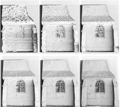
As photographs’ positions are known, a global similarity is calculated with the open source MicMac (Pierrot-Deseilligny M. et al, 2006) by a multi-view stereo correlation. The matching has a multi-scale, multi-resolution, pyramidal approach (Figure 1).
Figure 1: Pyramidal approach: example of results during the multi-scale matching
4.3 Point cloud generation
Starting from positions and orientations of photographs, as well as the results of the multi-stereo correlation, the conversion of the depth maps into 3D metric points is performed. Each pixel of the master image is projected in space taking into account the orientation and position of the image and, then, a dense point cloud is created for each master image (Figure 2).
Figure 2: The multi-stereo image matching method: the master image (left), the matching result in the last pyramidal step
(center) and the generated colorized point cloud (right)
Figure 3: Superposition of point cloud of all master images
4.4 XYZ Files
Using the point cloud generated for each master image, the coordinates in space of each pixel of the image are known. These coordinates are then stored in TIFF files named XYZ files.
A TIFF file is an image file composed of three layers associated each to a primary color (Red, Green and Blue : RGB) in order to store color information of an image. A color of a pixel is represented as a combination of values between 0 and 255 of red, green and blue. Each layer can be considered as an array containing one of the three values of the pixels’ color. The color of a pixel is the result of the association of the three values (Figure 4).
Figure 4: Structure of a TIFF file with the three color’s layers: Red, Green, Blue
XYZ files use the three-layer structure of TIFF files to store the 3D coordinates (X, Y and Z) of pixels instead of storing color information on the image. The red layer contains the X coordinates, the green layer contains the Y coordinates and the blue layer contains the Z coordinates. Thus, three arrays are available; each of them containing one of the three coordinates (Figure 5).
Figure 5: Structure of XYZ files with the three coordinates: X, Y and Z.
As each pixel is associated to an X, Y and Z triplet of coordinates, these three arrays have the same size as the corresponding image.
One of a pixel’s coordinates could be extracted from the associated XYZ file by reading the value in the array containing this coordinate. This value is at the same row and column as the pixel in the image. Thus, knowing the row i and the column j in the image of a pixel, the X coordinate‘s value of this pixel is the value at the row i and the column j in the X array of the XYZ file associated to the image.
5. METHODOLOGY FOR THE PROPAGATION OF ANNOTATIONS
The adopted methodology for the propagation of annotations between images uses XYZ files containing the coordinates. The propagation consists in three steps (Figure 6):
Definition of the annotation on one image
Research of the coordinates X, Y and Z of the annotated area
Projection on the other images of the set
Figure 6: Steps of transfer: (a) definition of the annotation on the middle image, (b) research of X, Y and Z coordinate of the
area, (c) projection on the other images
Each annotation will be defined by a set of triplets of coordinates in space.
5.1 Definition of annotations
Starting from an area drawn on one of images of the set, a mask is constructed: it is same-sized as the image and contains white area on a black background where the white area corresponds to the drawn area (Figure 7).
XYZ File
Z Coordinates array
Y Coordinates array
X Coordinates array
(a) (b)
Figure 7: Drawn area (up) and extracted mask (down)
5.2 Research of the 3D coordinates of the area
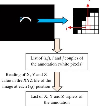
As the white area in the mask represents the annotation on the image, the position (row and column) of pixels of this area must be known in order to extract the corresponding X, Y and Z coordinates. In this way, all positions of white pixels of the mask are searched and a list of couples of values i (row) and j (column) is constructed. Knowing the concerned positions, the list of corresponding X, Y and Z triplets is given by the reading of X, Y and Z coordinates at these positions in the XYZ file of the image (Figure 8).
Figure 8: Research of X, Y and Z coordinates of the annotation
The annotated area is so defined in space by this list of X, Y and Z triplets (Figure 9).
Figure 9: 3D representation of the coordinates list of the annotation
5.3 Projection on the others pictures
Having the X, Y and Z coordinates of the points representing the annotation, these points can be retrieved in the other images of the set by using XYZ files.
Each coordinates’ triplets of the annotation is compared with all X, Y and Z coordinates of the XYZ files attached to the image on which the annotation must be transferred (Figure 10).
Figure 10: A comparison between the list of X, Y and Z triplets of the annotation and the XYZ files helps to project the
annotation on the other images
Each XYZ file is scanned in order to retrieve all positions (row/column couple) where the X, Y and Z triplets of coordinates is corresponding to one of the X, Y and Z triplets of the annotation. When a triplet of coordinates of the XYZ file is corresponding to one of the triplets of the annotation, the associated position is defined as true. All other positions are defined as false. Thus, if an X, Y and Z triplets is not finding in the XYZ file that means the associated point does not appear in image.
Figure 11: Research of true position and false position on the image
Starting from true and false positions for a XYZ file, a mask is then constructed, where true positions are represented by white pixels and false positions by black pixels (Figure 12).
Figure 12: Interpretation of true and false positions for mask’s construction
i
List of (i,j), i and j couples of the annotation (white pixels)
List of X, Y and Z triplets of the annotation Reading of X, Y and Z
value in the XYZ file of the image at each (i,j) position
List of X, Y and Z
triplets of the annotation Comparison XYZ File
List of X, Y and Z triplets of
the annotation (i,j) position
X,Y and Z coordinates
Reading of X, Y and Z values in the XYZ file at the (i,j) position
Comparison
One of the annotation’s triplets
corresponds
None of the annotation’s triplets
corresponds 2 possibilities
True position False position
(i,j) true position (i,j) false position
(i,j) position on the mask : white
pixel
(i,j) position on the mask : black
Detected areas appear so in the mask as white areas. As all positions are tested in a XYZ file, the mask has the same dimension as the XYZ file and so as the attached image (Figure 13).
Figure 13: Image (left) and associated mask by the propagation of annotation (right)
In the event that the drawn area (corresponding to the annotation) does not appears in one of the other images, the created mask for this image will be only composed of black pixels.
The annotated area can be displayed by superimposing the image and the mask, and by affecting a transparency value on the mask and a color value on white pixels (Figure 14).
Figure 14: Visualisation of the area on another image
In this process, the transfer can be performed in two ways for an image: from the picture (definition of an annotation) or to the picture (transfer from another picture).
5.4 Multi-view enrichment of annotations
This transfer only allows the search of existing points on the annotated image. But the object to be annotated frequently does not appear wholly in any image. Indeed, in these cases, other views are needed to completely select this object.
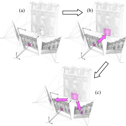
For this reason, the objective of multi-view enrichment is to permit the user to define an annotation from different views while using the propagation’s method previously presented. A first list of X, Y and Z coordinates is extracted by implementing the steps 5.1 and 5.2 on this view. Then the steps 5.1 and 5.2 are implemented again on another view and a second list of X, Y and Z coordinates is extracted. By grouping together these two lists, a third one, representing the whole annotation, is created. Finally the step 5.3 is processed for all images by using the combination of the two extracted lists (Figure 15).
Figure 15: Steps of multi-view definition: (a) definition of a part of the annotation on a view and search of X, Y and Z coordinates (pink), (b) definition of a second part of the
annotation on another view and search of X, Y and Z coordinates (blue), (c) association of the two list of coordinates
(green), (d) projection of the modified annotation on others images
These steps can be generalised for the use of more than two images. It is sufficient to repeat steps 5.1 and 5.2 on each concerned images and, then, to assemble all the lists of coordinates before implementing step 5.3.
Thus, this enrichment of annotations can be performed from different viewpoints and the definition of an annotation can be defined at best.
6. CONCLUSION AND PERSPECTIVES
This work has shown a process based on 3D information to transfer annotation towards a set of spatially oriented pictures of a building. Despite the results obtained with this study, some issues need to be resolved and some reflections should prompt further research.
First of all, in order to improve the definition and the transfer of an annotation, an automatic segmentation of the image or of the implicit point cloud (implicit because contained in the XYZ files) could be envisaged. For example, with an efficient segmentation of images, the definition of annotations could be implemented by selecting parts of the segmentation and the transfer could be implemented by detecting parts of the segmentation instead of detecting pixels.
Besides, as different levels of semantic description could exist, the overlapping of annotations should be envisaged and managed.
Then, a set of 2D or 3D analyse tools (color, shape …) could be developed, with the help of images or point cloud.
Afterward, the adding of new photographs to the already annotated images should be provided by the system.
Furthermore, as the state of a building evolves in time, the management of images from different time can be expected. At last, if annotations are semantically defined, several queries (by single annotation, by terms …) could be formulated with the crossing of all data according to different criteria.
(c) (b) (a)
7. REFERENCES
Attene M., Robbiano F., Spagnuolo M., Falcidieno B., 2009, Part-based Annotation of Virtual 3D Shapes.
Barrat S., Tabbone S., 2009, Classification et extension automatique d’annotations d’images en utilisant un réseau Bayesien.
Bilasco I.M., Gensel J., Villanova-Oliver M., Martin H., 2005, 3DSEAM: a model for annotating 3D scenes using MPEG-7.
Busayarat C., 2010, La maquette numérique comme support pour la recherche visuelle d’informations patrimoniales.
Halaschek-Wiener C., Jennifer G., Andrew S., Michael G., Bijan P., Jim H., 2005, PhotoStuff -- An Image Annotation Tool for the Semantic Web.
Havemann S., Settgast V., Berndt R., Eide O., Fellner D.W., 2008, The Arrigo Showcase Reloaded – Towards a sustainable link between 3D and semantics
Hunter J., Yu C.H., 2011, Assessing the Value of Semantic Annotation for 3D Museum Artifacts
Petridis K, Anastasopoulos D, Saathoff C, Timmermann N, Kompatsiaris I, Staab S, 2006, M-OntoMat-Annotizer: Image annotation linking ontologies and multimedia low-level features. KES 2006 10th Intnl. conf. on knowledge based, intelligent information and engineering systems.
Pierrot-Deseilligny M., Paparoditis N., 2006, A multiresolution and optimization-based image matching approach: An application to surface reconstruction from SPOT5-HRS stereo imagery.
Pierrot-Deseilligny M., De Luca L., Remondino F., 2011a, Automated image-based procedures for accurate artifacts 3D modeling and orthopicture generation.
Pierrot-Deseilligny M., Clery I., 2011b, APERO, an open source bundle adjustment software for automatic calibration and orientation of set of images, Int. Archives of Photogrammetry, Remote Sensing and Spatial Information Sciences, 38(5/W16), on CD-ROM. ISPRS Int. Workshop 3D-ARCH 2011, Trento, Italy.
Pittarello F., De Faveri A., 2006, Semantic Description of 3D Environments: a Proposal Based on Web Standards.
Shotton, J.D.J., Winn, J., Rother, C., Criminisi, A., 2009, TextonBoost for Image Understanding: Multi-Class Object Recognition and Segmentation by Jointly Modeling Texture, Layout, and Context, IJCV(81), No. 1.