THE DEVELOPMENT OF A FAMILY OF LIGHTWEIGHT AND WIDE SWATH UAV
CAMERA SYSTEMS AROUND AN INNOVATIVE DUAL-SENSOR ON-SINGLE-CHIP
DETECTOR
B. Delauré, B. Michiels, N. Lewyckyj , T. Van Achteren
VITO Flemish Institute for Technological Research, Boeretang 200 2400 Mol, (bavo.delaure; bart.michiels; Nicolas.lewyckyj; tanja.vanachteren)@vito.be
KEY WORDS: camera, unmanned aerial vehicle, CMOS sensor, hyperspectral
ABSTRACT:
Together with a Belgian industrial consortium VITO has developed the lightweight camera system MEDUSA. It combines high spatial resolution with a wide swath to support missions for large scale mapping and disaster monitoring applications. MEDUSA has been designed to be operated on a solar-powered unmanned aerial vehicle flying in the stratosphere. The camera system contains a custom designed CMOS imager with 2 sensors (each having 10000 x1200 pixels) on 1 chip. One sensor is panchromatic, one is equipped with colour filters. The MEDUSA flight model camera has passed an extensive test campaign and is ready to conduct its maiden flight. First airborne test flights with an engineering model version of the camera have been executed to validate the functionality and the performance of the camera. An image stitching work flow has been developed in order to generate an image composite in near real time of the acquired images. The unique properties of the dual-sensor-on-single-chip detector triggered the development of 2 new camera designs which are currently in preparation. MEDUSA-low is a modified camera system optimised for compatibility with more conventional UAV systems with a payload capacity of 5-10 kg flying at an altitude around 1 km. Its camera acquires both panchromatic and colour images. The MEDUSA geospectral camera is an innovative hyperspectral imager which is equipped with a spatially varying spectral filter installed in front of one of the two sensors. It acquires both hyperspectral and broad band high spatial resolution image data from one and the same camera.
1. INTRODUCTION
Traditionally earth observation is being conducted from airborne and satellite platforms, each having specific advantages regarding parameters such as spatial resolution, ground coverage, availability and flexibility. Depending on the application one platform is better suited than the other. Various technological developments over the last decade have lead to a new type of platform which bridges the gap between manned aircraft and satellites: a local geostationary system operated in the stratosphere. Various platform concepts, mostly airships or aircraft, are being developed aiming at persistent availability for earth observation as well as for telecommunications purposes. Besides the research performed regarding the platform, an additional challenge lies in the development of instruments which are adapted to the new specifications, environmental and operational conditions of those innovative platforms.
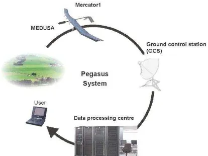
Within the Pegasus program [Everaerts, 2004] initiated by VITO, the Flemish Institute for Technological research, a lightweight high resolution camera MEDUSA was developed to fly on a solar-powered high altitude long endurance (HALE) unmanned aerial vehicle (UAV) at stratospheric altitudes around 18 km. This aircraft is powered by solar energy and high capacity batteries allowing it to fly for weeks or even months without landing. As such it can be used as local geostationary system, as it is able to remain above a region persistently. The platform is not bound to an orbit and moves at low speed in a region of the atmosphere where wind speeds are limited. The longest unmanned flight with such a platform was realized in 2010 by QinetiQ, it had a duration of 14 days [QinetiQ 2010].
Figure 1 Schematic overview of the Pegasus system
The target applications for the Pegasus initiative are large scale mapping and disaster monitoring. For this reason two types of missions are considered:
Mapping a large area with the aim of supplying a high quality image product of each location in the area once.
Monitoring a small dedicated zone at a high temporal update rate where image products are supplied in near-real time with lower image quality but acceptable for the user.
These two mission types have been the driver for the MEDUSA camera design.
Disaster mapping missions aim at providing a tactical overview of an area relatively modest size. Speed is main goal, while the quality of the mapping is less important. The wide swath of the instrument serves this purpose. High spatial resolution is wanted to allow a good assessment of the situation, but a high geo-location accuracy is not the first priority.
Large scale mapping missions have a very different focus. They devote more time in order to achieve high quality imagery, including highly accurate geo-location and mapping, which allows to use the products for photogrammetric purposes. To achieve this, imaging with optimal overlap between successive images is used, as well as advanced mapping software
2. MEDUSA HALE UAV CAMERA
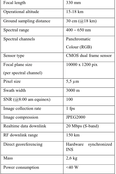
In order to accomplish disaster monitoring and large-scale mapping a high resolution camera system, MEDUSA (Monitoring Equipment and Devices for Unmanned Systems at high Altitude), has been developed by a Belgian industrial consortium led by VITO [Van Achteren 2007, Van Achteren, 2013] under the ESA-PRODEX program. The top-level instrument requirements extracted from the target applications are summarized in Table 1.
2.1 Specifications and constraints
Focal length 330 mm
Operational altitude 15-18 km
Ground sampling distance 30 cm (@18 km)
Spectral range 400 – 650 nm
Spectral channels Panchromatic
Colour (RGB)
Sensor type CMOS dual frame sensor
Focal plane size
Image collection rate 1 fps
Image compression JPEG2000
Realtime data downlink 20 Mbps (S-band)
RF downlink range 150 km
Direct georeferencing Hardware synchronized INS physical and environmental conditions. As the UAV platform is extremely low-weight (around 35 kg), the total allowed mass for the payload is also strict: 2 to 3 kg depending on the duration of the mission. The pressure at operational altitude is around 60 mbar. The total power consumption is limited to 50 W during the day. No power is available at night, and all mechanical and electronics components have to survive severe thermal cycles with temperatures in worst cases down to -70°C and up to 60°C. Thermal gradients and temperature evolutions are also experienced over the day, mainly due to the change in sun elevation and the direction of flight. The volume of the payload is restricted to a more or less cylindrical tube of 1 meter length with an outer diameter of 12cm.
The lower stratosphere’s environment is characterized by low air pressure (down to 60 mbar) and low relative humidity. The ambient temperature is low. Based on averaged temperature– data acquired above Belgium over a 20 year period we expect it to vary around -55°C with a 3 sigma deviation of about 15°C. Apart from the fluctuating air temperature, the temperature within the instrument is governed by two main heat sources: the sun (external) and electronic power dissipation (internal). As the MEDUSA camera system is not screened by the airplane against external influences it experiences a strong temperature variation induced by the relative orientation of the sun with respect to the instrument.
2.2 System design
The MEDUSA camera is designed along the horizontal axis to allow integration at the front of the Mercator HALE UAV. The instrument is by design divided into two parts:
Optical compartment
Electronics compartment
The optical compartment houses a refractive optical system with a thermal compensation mechanism to adapt the focus position of the CMOS sensor relative to the optical system as a function of the temperature inside the payload. The electronics compartment hosts the different electronic modules: CMOS sensor read-out and on-board computer, GPS receiver and antenna, inertial measurement unit and S-band data transmission system. A schematic layout of the MEDUSA camera is shown in Figure 2.
Figure 2 MEDUSA schematic layout
Both compartments of the MEDUSA camera have a lightweight carbon fiber housing. Aerodynamic fairings reduce the drag of the camera system. Figure 3 shows the integrated MEDUSA HALE UAV camera.
Figure 3 integrated MEDUSA HALE UAV camera
2.3 Dual sensor on single chip
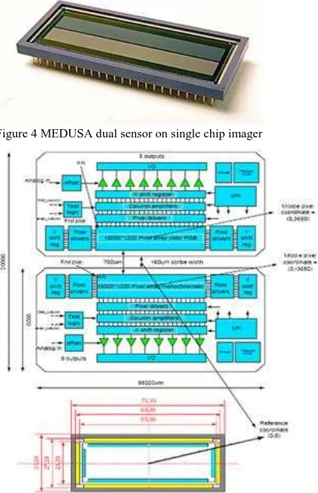
To be able to realize the instrument specifications of MEDUSA in terms of signal-to-noise ratio, image quality, swath and spatial resolution a innovative detector design has been proposed. The MEDUSA CMOS sensor consists of 2 independently controllable image frame sensors on one single chip. One sensor is equipped with colour filters organised in a RGB Bayer configuration. The second sensor is panchromatic and thus sensitive to a wider spectral range. A picture of the imager chip is shown in Figure 4.
Each sensor consists of 10000 x 1200 pixels with a pitch of 5,5 µm. The two sensor elements are separated by a distance of 700 µm. Because the sensors are located on a single die, they are very accurately aligned. The MEDUSA sensor is equipped with micro-lenses to increase the light intensity on the sensitive area of the pixel.
Figure 4 MEDUSA dual sensor on single chip imager
Figure 5: MEDUSA sensor chip top level architecture
The image sensor has been developed by Cypress Semiconductor Cooperation Belgium (now ON-Semiconductor) for the MEDUSA camera system. The sensor architecture is shown in Figure 5.The most important specifications of the MEDUSA CMOS sensor are listed in Table 2. More details can be found in [Delauré 2009]. A typical image recorded by the MEDUSA CMOS sensor is shown in Figure 6.
Figure 6: image acquired with the panchromatic sensor
Die size 58mm*9.92mm
Array size 10000 (H) x 1200 (V)
Maximal frame rate 33 fps at full resolution Shutter type Pipelined snapshot shutter Power consumption <0.5W
Operating temperature -40ºC to 60ºC
Color Panchromatic and Color (same
die)
Pixel type 6T variant
Pixel size 5.5 μm x 5.5 μm
Peak QE 48% 550nm, with micro lenses
Conversion gain 35 μV/eˉ
Temporal dark noise 28eˉ Pixel saturation charge >35000 eˉ
Dynamic range 62dB
Dark current 6mV/s at 20ºC
PLS <1/30000
MTF @ 630nm @ Nyquist freq. >60% in both X and Y directions
Table 2 most important specifications of the MEDUSA CMOS sensor
2.4 Image processing
As described above the requirements of the image product in terms of image quality and time-to-delivery are governed by the application and corresponding mission type. For missions which are not time critical dedicated image preprocessing can be applied in order to realize a high quality image mosaic. Commercial photogrammetric software packages are available to achieve this. In this paper an image composite is shown created with Agisoft Photoscan.
For near real time applications like disaster monitoring and surveillance missions, the requirements are different. Speed is primordial, while the accuracy of the mapping can be lower. Thus, an approach is need in which the balance between operational speed and allowable distortions is chosen differently. A dedicated fast stitching workflow has been developed at VITO to support this.
In order to correctly stitch successive images acquired during a survey, the images have to be co-registered, i.e. it is needed to find the transformation that makes the images best aligned. The method used to co-register the different images tries to match image areas based on the pixel intensities. It computes a similarity measure between image pairs, of which one image is transformed by a random transformation. The similarity measure is computed for a number of possible transformations, after which the best transformation is selected as the one that registers the images [Haralick, 93; Jähne, 97].
Some modifications have however been made to this standard method in order to increase the processing speed to near real-time and to build in some quality control mechanisms. Additionally, depending on the image content, some frames can be automatically skipped to enhance the process.
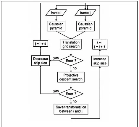
Figure 7 gives a general overview of the algorithm. Two frames i and j = i + s are first selected from the image sequence, s being the skip size. Their respective Gaussian pyramids are constructed, followed by a preliminary rough registration using translations only. An error check is then performed. If successful, the registration continues with a descent search allowing full projective transformations. A second error check is then performed. If the second check is successful, the result is stored and the process continues with the next frame pair. If the error check fails, the software tries to register again the same frame i, but this time with a closer frame j = i + (s / 2). When all frames are correctly processed, a mosaic from the stored images is created.
Figure 7 functional flow of the image stitcher
3. MEDUSA ENGINEERING UNIT
3.1 Camera system
In order to conduct MEDUSA test flights at an early stage in the development to demonstrate the functionality of the camera system an engineering model of the MEDUSA camera has been built. The engineering unit contains a number of exact copies of the electronic subsystems of the MEDUSA HALE UAV camera: i.e. CMOS sensor and read-out, on-board computer, GPS receiver, inertial measurement unit, power regulation and distribution unit. The CMOS sensor is installed in a COTS Hasselblad camera body with 80 mm lens and operated at a maximum frame rate of 1 fps. While the sensor itself can handle much higher frame rates, 1 fps is adequate for the imaging purpose and also keeps the data flow to a manageable level..
The MEDUSA engineering model camera is not yet equipped with a data transmitter. Instead all image and meta-data is stored on a on-board industrial computer. All subsystems are integrated in a ruggedized mechanical housing as shown in Figure 8. A COTS dual frequency GPS antenna is installed outside of the housing for GPS reception.
Figure 8 MEDUSA engineering model installed at the basket of the balloon
Figure 9 double image (panchromatic and colour) acquired by the MEDUSA engineering model during the balloon flight of 2012 – 10 cm ground sampling distance - 1 km swath
Figure 10 double image (panchromatic and colour) acquired by the MEDUSA engineering model during the balloon flight of 2012 – 10 cm ground sampling distance - 1 km swath
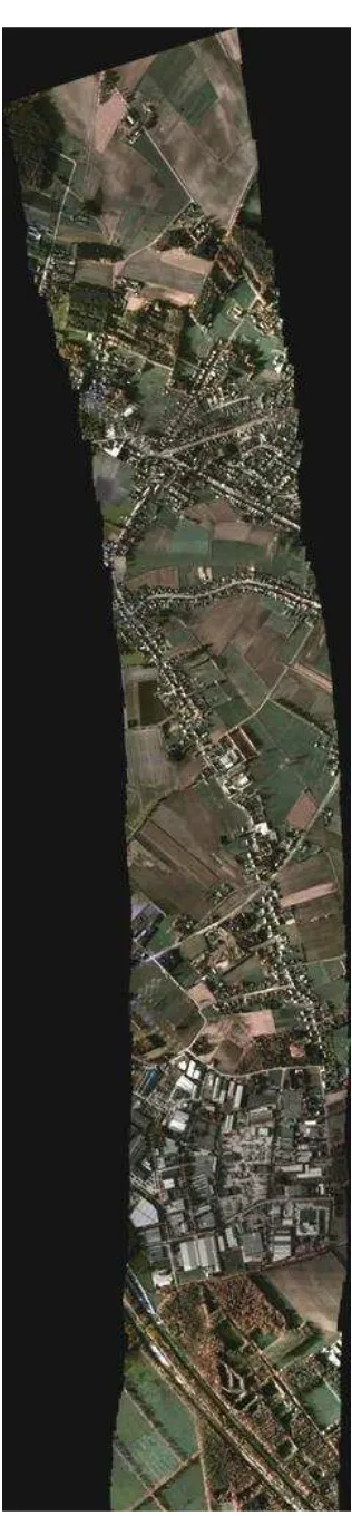
Figure 11 image composite of a set of panchromatic images produced with Agisoft Photoscan 10 cm ground sampling distance - 1 km swath
3.2 Flight campaign
In autumn 2012 the MEDUSA engineering model was embarked on a manned balloon and flown in a 1,5 h mission at an altitude of around 1,5 km. The camera was operated at a frame rate of 1 fps and acquired both panchromatic and colour images at a ground sampling distance of 10 cm and a swath of 1 km. Figure 9 and Figure 10 show a typical image of the MEDUSA camera system. Figure 8 shows a composite of panchromatic images of a limited set of images.
The acquired image data set have been processed in two ways to generate two image composites:
Block bundle adjustement using Agisoft Photoscan was applied on the panchromatic images (Figure 11)
Image stitching module applied on a set of colour images as described above (Figure 13)
Figure 12 region of interest from the panchromatic composite as shown in Figure 11
4. MEDUSA-L
Since the MEDUSA engineering model camera is built for demonstration purposes from manned platforms it is not compatible with small and medium sized UAV systems. Therefore VITO is preparing the development of a camera system which is mechanically and electrically compatible with more conventional unmanned platforms. The development is targeting platforms with a payload capacity of 5-10 kg.
The MEDUSA-L (low altitude), intended to fly at lower altitudes, consists of the same core elements as the MEDUSA-FM (flight model) and MEDUSA-EM (engineering model) i.e. MEDUS CMOS sensor, read-out electronics and on-board processing unit, GPS receiver and inertial measurement unit. The optical specifications of the MEDUSA-L camera are identical as the MEDUSA engineering model. For this reason the MEDUSA EM data set is very representative for the MEDUSA-L camera.
5. MEDUSA GEOSPECTRAL CAMERA
The elongated form factor of the MEDUSA CMOS sensor (10000x1200 pixels) the MEDUSA imager chip makes it very well suited for use in hyperspectral imaging. A wide swath camera can be realized by means of the long size of the sensor in the across direction. The 1200 lines along the short direction of the sensor can be exploited to project dispersed or filtered light in many different spectral bands.
Figure 13 image composite of a set of colour images using the image stitcher
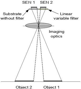
Using a spatially variable optical filter as spectral unit allows (e.g. a linear variable filter) it is possible to create a very compact hyperspectral imager. The filter is deposited on a glass
substrate which is installed just in front of the detector. This way each line on the detector acquires light from a specific
spectral band. By making a linear motion the complete reflectance spectrum can be reconstructed of a ground scene. An
image of a linear variable filter is shown in Figure 14. is a panchromatic sensor or a sensor equipped with a broad band filter. The 2 sensors on a single chip which can be independently controlled allow to acquire both hyperspectral images and broad band frame images (colour or panchromatic) from one single camera.
Figure 14 Linear variable optical filter
VITO has integrated a breadboard version of this type of camera with a linear variable filter with a FWHM of around 17 nm. First imaging tests have been conducted at ground level. Figure 16 shows a simulated image as acquired by the MEDUSA geospectral camera.
Figure 15 schematic representation of the geo-spectral camera with one panchromatic sensor element and one spectral sensor developed the lightweight high resolution camera system MEDUSA. It is designed to be operated on a solar-powered unmanned aerial vehicle flying in the stratosphere. The camera system contains a custom designed imager with 2 sensors on 1 chip. One sensor is panchromatic, one is equipped with colour filters. The flight model camera MEDUSA-FM has passed its test campaign and its ready for a first flight campaign.
The innovative dual sensor on single chip detector has at the basis of the design of 2 derived camera systems for more conventional platforms: MEDUSA-L and the geospectral camera. Those cameras are under development opening new opportunities for earth observation from medium sized unmanned aerial vehicles.
7. REFERENCES
Delauré, B., 2009, Proc. SPIE 7474, Sensors, Systems, and Next-Generation Satellites XIII, 74741D (September 22, 2009); doi:10.1117/12.830448
Delauré, B., 2013, “The geospectral camera: a compact and geometrically precise hyperspectral and high spatial resolution imager”, International Archives of the Photogrammetry, Remote Sensing and Spatial Information Sciences, Volume XL-1/W1, ISPRS Hannover Workshop 2013, 21 – 24 May 2013, Hannover, Germany
Everaerts, J., 2004, PEGASUS: Design of a stratospheric Long Endurance UAV System for Remote Sensing. The International Archives of the Photogrammetry , Remote Sensing and Spatial Information Sciences, Vol. XXXV, Part B
Haralick P. & Shapiro L., 1993, Computer and Robot Vision, Vol 2., Addison-wesley, Reading, MA
Jähne B., 1977, Digital Image processing, Algorithms and Scientific Applications, Springer-Verlag, Berlin
QinetiQ 2010, “Record breaking Zephyr offers 24/7 cost effective military surveillance and communications” (July 2010) http://www.qinetiq.com/news/pressreleases/Pages/world-record-UAV.aspx, accessed on 09/04/2013
Van Achteren, T., 2007, “MEDUSA, an ultra light weight multi-spectral camera for a HALE UAV”, SPIE Europe Conference on Remote Sensing, Firenze, Italy, Sept. 2007
Van Achteren, T., 2013, “A lightweight and wide swath UAV partners within the MEDUSA consortium (QinetiQ Space, Lambda-X, ON-Semi, Vector International, OMP, Antwerp Space, Septentrio, Inertial Sciences) for their support in the development of the MEDUSA FM high resolution camera system.
The European Commission for their support to the Airbeam-project through the FP7 security program SEN 1