GEOMETRIC PROPERTIES OF A MECHANICAL FORWARD
MOTION COMPENSATION SYSTEM CONTROLLED BY A PIEZOELECTRIC DRIVE
François Collette1 *, Simon Gline1, Julien Losseau1, Loïc Lecharlier2
1 Optech - DiMAC sprl, 7 Rue Edouard Belin, 1435 Mont-St-Guibert, Belgium, [email protected] 2
Mathematics Department, Faculty of Gembloux, University of Liège, Belgium, [email protected]
KEY WORDS: Digital airborne camera, Forward Motion Compensation, Piezoelectric drive, Geometrical quality, Compensation error, Radial distortion
ABSTRACT:
Forward Motion Compensation (FMC) systems have been designed to ensure the radiometric quality of motion acquisition in airborne cameras. If the radiometric benefits of FMC have been acknowledged, what are its effects on the geometrical properties of the camera? This paper demonstrates that FMC significantly improves geometrical properties of a camera. Aspects of FMC theory are discussed, with a focus on the near-lossless implementation of this technology into digital aerial camera systems. Among mechanical FMC technologies, the piezoelectric drive is proving to excel in dynamic positioning in both accuracy and repeatability. The patented piezoelectric drive integrated into Optech aerial camera systems allows for continuous and precise sensor motion to ensure exact compensation of the aircraft’s forward motion. This paper presents findings that demonstrate the validity of this assertion. The paper also discusses the physical principles involved in motion acquisition. Equations are included that define the motion effect at image level and illustrate how FMC acts to prevent motion effects. The residual motion effect or compensation error is formulated and a practical computation applied to the more restrictive camera case. The assessment concludes that, in the range of airborne camera utilization, the mechanical FMC technique is free of "visible" error at both human eye and computer assessment level. Lastly, the paper proceeds to a detailed technical discussion of piezoelectric drives and why they have proven to be so effective as nanopositioning devices for optical applications. The effectiveness of the patented piezoelectric drives used to achieve FMC in Optech cameras is conclusively demonstrated.
1. INTRODUCTION
1.1. The motion effect
Because the scene and sensor are moving relative to one another, the sensor perceives the scene as moving during image acquisition. This results in a directional blur called smear effect present all over the image and proportional to the scene displacement during exposure time. The close relationship between radiometry and geometry means that motion also acts on geometry of an image, leading to the motion-dependent geometrical quality of airborne cameras.
The simplest solution for camera manufacturers has been to limit the motion effect by reducing the exposure time as much as possible. But to counterbalance the lack of incoming light, this technique also imposes the use of wide apertures resulting in a loss of radiometric dynamism—contrast—which negatively impacts the overall image quality. The user therefore, has to choose between motion blur and low image contrast. In every case, the absence of Forward Motion Compensation (FMC) leads to a loss in radiometric quality.
1.2. The compensation principle
The solution to the motion effect did not wait for the arrival of digital sensors; it actually shows up very early in photogrammetry. Indeed, to preserve quality in motion acquisition, FMC techniques appeared in the most recognized film-based cameras that ruled the photogrammetric world for decades, both in terms of radiometry and geometry. The principle was to oppose scene displacement with an equivalent film displacement during the exposure time to temporally suppress the relative scene-sensor motion. In other words, the film followed the ramping scene projection throughout the
acquisition of the image. More and more, film-based cameras are being replaced by digital cameras, but the need for FMC remains. The following section assesses most common FMC possibilities with digital cameras.
1.3. Types of FMC
1.3.1. Camera displacement: The best technique a priori would be to move the whole camera relative to the ground during exposure time to counter the visual effect of the ground rushing past the camera’s field-of-view. But to achieve this, the camera would have to move at the speed of the aircraft, and in the opposite direction, over a distance long enough to cover the displacement during exposure time. Aircraft space constraints coupled with the destructive effects of quick acceleration and deceleration on the camera’s optical and electronic parts make such a principle mechanically impossible to implement and maintain. As the full camera could not physically handle such a technique, compensation would be performed at the sensor or image level where scene meters become image microns.
1.3.3. Image displacement: Here scene displacement is compensated by an electronic shifting of the image synchronized with the scene motion. The approach is commonly referred to as Time Delay Integration or TDI. This is made possible by shifting each electrical light measurement by row at the sensor level. This technique has the advantage of requiring no mechanical movement from any part. But the compensation principle is, by definition, limited because it offers a discrete correction as opposed to a continuous effect. Between two electronic shifts, the scene keeps moving and no motion compensation occurs. The acquisition sequences performed between shifts are made without compensation bringing motion blur in each sequence. The resulting image composed of the addition of the acquisition sequences shows motion blur equivalent to the one exhibited by the acquisition sequences. The image displacement technique could therefore not suppress all of the motion effect but keeps it at sub-pixel level. The visual benefits of such technique are evident but geometrical consequences of uncorrected motion blur can remain.
2. PHYSICAL PRINCIPLE ERROR
This section identifies the compensation error inherent in the FMC technique used by Optech, and based on continuous mechanical sensor displacement. The following section then describes how such a technique has been implemented in Optech cameras.
2.1. The projection principle
2.1.1. Static acquisition projection: All lenses create geometrical distortion in the projected image of a sort that a simple pinhole camera approach is not sufficient when considering scene point projection. Basically, there are two types of distortion: radial and tangential. While most radial distortion is inherent in the optical design of the lens, the tangential component appears with manufacturing and mounting variability of lens and camera.
In this paper, we consider the assembly as perfect (or close to perfect) so that the tangential component is absent or negligible. Assuming that all constitutive elements are perfectly aligned, the symmetry center of radial distortion fits with the image center. The distortion affecting each point projection of such a defined camera could be represented by the following standard polynomial model [1]:
Where r' and r represent the radial distance from the distortion center to the image point respectively, with and without distortion effect, dr(r) the radial distortion and Ki the coefficients of the polynomial equation. It is generally accepted to limit the equation size to three or four elements [1] to accurately map the distortion. Note that the above equation refers to the characteristic distortion representing the physical lens distortion pattern, not the calibrated distortion provided with camera calibration results.
Intrinsically defined in equation (1), radial distortion fits with radius orientation, inward or outward, to or from the distortion center according to its negative or positive value respectively.
The distortion effect could therefore be considered as a displacement vector affecting the point with the same orientation as the radius vector pointing toward its location, and with a magnitude and direction dependent on the radius dimension.
The radial distortion effect could also be re-formulated in a Cartesian coordinate system defined with its origin at the image center with the x axis parallel to the flight direction. The Cartesian formulation brings a cosines-sinus spread of the distortion effect between the two coordinates:
Where (x,y) are the distortion-free coordinates of the point, (x',y') are coordinates with a distortion effect, and α is the angle between radius vector and (positive) x axis.
2.1.2. Motion acquisition projection: The equations in the previous section assume a static projection pattern of the points all along the acquisition—in other words, a static image acquisition. With motion acquisition, the scene points observed by the lens are moving during the acquisition. The projection performed by the lens on each point is therefore variable and time dependent as well as the distortion applied to it. Equations (1) and (2) should therefore be considered as reflecting the projection at time t of the acquisition, and not as an answer for the whole acquisition window.
2.2. Error model
2.2.1. Error definition: Aside from motion effect, the quality loss at acquisition level is not created by the distortion of the projection but by the variation of this distortion along the acquisition time. With still image acquisition, the scene remains still during acquisition leading to distorted but static projection pattern making image geometrically distorted but radiometrically sharp. With motion acquisition, the point is moving during the acquisition, and so the radius vector associated with the point changes in magnitude and orientation, affecting accordingly, the magnitude and orientation of the distortion effect. The projected point is therefore moving a) because of the aircraft’s motion, and b) because of the distortion effect variation. This results in pixel dilution in neighbor pixels creating smear effect radiometrically visible and geometrically damageable.
Most of the time, the impact of the distortion effect variation is set aside because point motion consequence is anticipated as being far more critical. In our case, the removal of the motion effect by FMC makes this side effect the only one to assess. The compensation error assessed in this section could therefore be defined as the amount of uncorrected motion effect resulting of the distortion effect variation along exposure time. Now stated, let us compute and assess what is usually considered to be negligible.
Where ∆x and ∆y are the Cartesian components of image point displacement equivalent to scene displacement, ∆x' and ∆y' are the effective image point displacement components with distortion effect, "0" and "1" indices defining respectively the value of indexed variables at the beginning and end of the acquisition time.
The first member of the equation solution represents the strict motion effect translation from scene to sensor with no projection "deformation". The second member describes the error added by the presence of distortion in the projection equation. The positioning and distortion factor identifying the acquisition time are established respectively under the first and second components of this second member.
Assuming the main effect of the motion occurs along the aircraft’s forward direction (∆y = 0), and considering the action of the FMC at the projection level (∆x = 0 under the projection component), the expression (3) becomes:
This formulation corresponds to the compensation error or motion effect the FMC technique is unable to handle. The Cartesian formulation has been made for practical aspects when considering the motion effect aligned with Cartesian image axes. Now completed, let us come back to the absolute error definition represented by its only dimension leaving aside the effect orientation (angle) and sign (direction):
The removal of the error sign in the computation is imposed by the observation that positive or negative, the error affects point quality identically while the sign presence could minimize the assessment indices employed in the following section.
2.3. Numerical error computation
2.3.1. Error computation: From previous equations established at the point level, the error computation could be generalized to the image level using numerical analysis by discrete computation. The method handles the surface to compute not as an infinite sum of points, but as a grid of very small squares of identical surface, inside of which all points present the same behavior. As each small area gathers points acting in the same way, the computation could be limited to only the center point to represent behavior in the small area. Utilizing such a computation method is relevant in regard to the very slow variation of distortion curves.
The error computation has been applied to CS-10000 cameras equipped with 80Mp sensor providing an image size of 10,328 by 7,760 pixels presenting a 5.2 by 5.2µm metric dimension. The camera has been considered in its standard configuration with longest image dimension across flight direction. The computation could have been made for each possible lens
provided with CS-10000 cameras but previous sections have demonstrated small distortion changes would not maximize error creation. Based on the characteristic distortion curves reported in Figure 1 and corresponding to equation (1) definition, the 50mm lens used with CS-10000 camera has been selected to illustrate the more discriminating case possible.
Figure 1 - Radial distortion of CS-10000 camera lenses (50, 70, 120 and 210mm focal length)
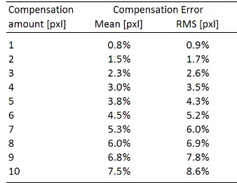
2.3.2. Error assessment: A first error assessment at image level has been made through the computation of the compensation error mean as an overall motion blur quantity estimation. A second approach has been performed by assessing the static projection inaccuracy through computation of the RMS of the error. As the assessed values already represent the error itself, RMS has been preferred over RMSE to avoid artificial minimization of the error estimation. The computation results are presented in Table 2.
Table 2 - Mean and RMS of compensation error for CS-10000 camera mounted with 50mm lens
15%, leading to the consideration that, below this value, point dilution is virtually equivalent to zero.
From Table 2, it appears that 0.9% of pixel RMS error is added for each compensated pixel. The visible linearity between cause and effect confirms the very slow distortion variation of the lens. Under normal acquisition conditions and plane configuration, the compensation rarely exceeds 5 pixels so that the RMS error is not bigger than 4.3% of the pixel. In extreme specific conditions, we can raise the compensation to 10 pixels, but this still leads to only 8.6%. To exceed the error threshold of 15% and so become "visible", the compensation would have to reach 17.4 pixels.
Practically, with an aircraft speed of 200 knots and a ground sample distance of 0.10m, the exposure time would have to last longer than 1/57 (17.5 ms) before the compensation starts to create a geometrically visible error. In comparison, to keep the error below the same 15% limit, the exposure time without FMC could not exceed 1/6800 (0.15ms). Any longer exposure time would generate geometrically visible error. Typical exposure of 1/2000 (0.50ms) and 1/4000 (0.25ms) are already off considerations while 1/8000 (0.13ms) keeps motion blur below visible level but makes radiometric image quality poor because of short exposure time.
Additionally, mechanical FMC by continuous sensor displacement not only improves image geometry quality, but it also keeps it identical among all projects. As the image geometry is not impacted by motion, the camera definition does not change between projects as it is not affected by a variable blur amount. The image quality and through it, the camera definition quality, remain identically accurate between projects. The quality of the camera manufacturer’s definition is also preserved between projects as acquisition conditions do not impact image quality and geometry.
In conclusion, at the sensibility levels established by both human and machine actors in the image chain, the principle of FMC by continuous sensor displacement has been demonstrated as being free of visible compensation error.
3. PRACTICAL IMPLEMENTATION
This section details how the FMC principle described in the previous section was implemented in Optech cameras, not only with respect to principle requirements, but also for the practical needs of aerial photography.
3.1. Piezoelectricity
Piezoelectricity is the property of certain materials to generate an electrical charge when submitted to a mechanical deformation. The phenomenon works in both directions so the inverse property is also ensured: when these materials are submitted to an electrical field, they react with a corresponding mechanical deformation. The phenomenon originates at the atomic level of the piezoelectric material. Natural materials with piezoelectric characteristics (e.g., quartz) exist, but here the magnitude of the effect is very slight. Industrial ceramics have been developed to maximize piezoelectric effect from an extremely small amount of material. Minimizing the amount of material allows for a finer level of predictability and therefore, deep control of the material’s behavior when used in precision applications.
3.2. Nanopositioning piezoelectric drive
3.2.1. Definition: The piezoelectric effect is converted in positioning mechanism by using piezoactuators that constrain the piezoelectric material to work predictably and along a single axis. These actuators allow the conversion of the raw piezoelectric property in a fully controlled positioning device responding accurately to a voltage command. Actuators can be combined in many types of piezoelectric drives with coupled or independent displacement to enable response to multiple application needs in terms of both position and angles. Specific flexure system ensures near-exact straightness and flatness of the drive motion along the desired axis.
3.2.2. Material properties: The strengths of piezoactuators and their various drive-mounts are many, but their main properties can be summarized as follows [2]:
- Sub-nanometer positioning precision with unlimited theoretical resolution
- Fast response
- High force production allowing high payload motion - Long life cycle due to absence of mechanical parts - No generation of magnetic fields nor susceptibility to
external ones
- Absence of lubricants or coating ensures compatibility un clean environments
- Wide operating temperature
As seen above, the unconstrained properties of piezoelectric materials and the complete freedom of piezoactuator configuration and combination allow for unlimited piezoelectric drive properties.
3.2.3. Aspects of dynamics: Aside from their material aspects, the limits of piezoelectric drives can be classified under three phenomena: hysteresis, drift and resonance. Because of hysteresis, displacement imperfectly follows the voltage curve provided to the drive, which leads to non-linearity between command and displacement. Following a change of position, the drift creates an additional small displacement of the piezoelectric platform without any modification in the command applied. Lastly, dynamic behavior could be impacted by the resonance effect of the piezoelectric drive that could limit the system response. The resonant frequency that characterizes the drive should therefore be considered with respect to the mass and dimensions of the mobile object.
3.2.4. Open loop: With a classic open loop control, the execution of the command is not controlled and the three dynamic effects listed above are free to appear. As a consequence, some piezoelectric drive performance required by the application may be affected. Depending on affected properties, the effects may have limiting, small or no consequences on the application. Each specific application therefore has to be assessed to confirm that the selected piezoelectric drive can be used efficiently in an open loop configuration.
servo-controller, electronic noise is added to the control decision which usually leads to a reduction in drive resolution.
As stated, the capabilities of a piezoelectric drive are not only related to its material properties, but also to the control mode used to operate it. Both control modes present specific advantages, making one preferable to the other in certain applications. Therefore, selecting the control mode is made in accordance with the performance required by the application.
3.3. Sensor displacement implementation
3.3.1. Needs: To implement continuous sensor displacement FMC, a high degree of linearity, repeatability and accuracy in dynamic performance were the key features. Accuracy and repeatability ensure the geometrical accuracy of FMC while the linearity of the correction is imposed by the assumption that the aircraft motion is constant during image acquisition.
Due to its location inside of camera body, the device also had to be small enough to fit and be compatible with a clean environment and generate no wear particles. In close contact with the sensor, electric or magnetic interactions were not allowed. A long life cycle under full performance conditions was necessary to ensure uninterrupted operational activities. Lastly, the device had to offer full performance and be compatible in an aerial acquisition environment with a travel range sufficient to meet large compensation needs.
3.3.2. Non-piezoeletric solution: To implement the FMC technique, various displacement devices (motor or spring, for instance) were assessed, but the advantages of a nanopositioning linear piezoelectric drive soon became obvious. Indeed, face to high resolution sensor and range of aircraft speed, a range of displacement at nanometer level was required to prevent significant error addition. The property of piezoelectric nanopositioning drive to fulfill this requirement was clear in regard to any electromechanical motors or moving devices. Other limitations of non-piezoelectric devices are due to the presence of mechanical parts affected by constricted movement, friction as well as wear and tear. Performance level and durability would be compromised by maintenance needs that negatively impact quality and longevity in the corresponding FMC. Therefore, a piezoelectric solution was required.
3.3.3. Piezoelectric solution: The dynamic capabilities of the piezoelectric drive have been optimized by the selection of a closed loop control that ensures the necessary accuracy, repeatability and linearity that FMC demands. Indeed, hysteresis and drift effects are nullified by servo-control. The closed loop configuration offers higher execution reliability and allows for assembly resonance handling. If resonance is present but ignored during compensation the result would be imperfect and variable with each changing compensation request.
To allow for evolving capabilities with future sensor upgrades, the piezoelectric drive has been selected to exceed the current technical needs with a resolution within a sub-nanometer range [2] and repeatability within a nanometer range [2]. The displacement range has also been selected to allow for excess compensation capabilities, leaving the user free to set any necessary combination of aperture and exposure to ensure image quality in any lighting conditions.
A complete numerical demonstration of the piezoelectric drive positioning error does not fit with the scope of this paper and is
left to an upcoming paper. Nevertheless, the above information provides a solid estimation of the range of values provided by piezoelectric drive positioning. Considering the sub-micrometric range of FMC compensation error (see Table 2), the error added by piezoelectric drive appears insignificant validating piezoelectric drive selection for efficient continuous FMC implementation.
4. CONCLUSIONS
Although FMC is known for its beneficial impact on radiometric image quality, the benefits of FMC are not as obvious when it comes to the geometry of imagery.
By considering the physical principles that contribute to distortion in aerial image acquisition, it has been demonstrated that FMC significantly improves the geometrical properties of the camera. Mathematical modeling and practical assessment demonstrate that any visible compensation error can be removed from data acquisition with the use of a FMC mechanism as long as it allows for continuous sensor displacement.
Making the reader aware of such error was the first intent of this study, introducing a practical solution to ensure continuous sensor displacement was the second objective of this paper.
Among mechanical FMC technologies, the piezoelectric drive is proving to excel in dynamic positioning both in accuracy and repeatability. It makes it, by far, the most adequate and efficient solution to compensate for motion effects leading to unrivaled radiometric and geometric solution.
Looking towards the future, piezoelectric drive and its nanopositioning superiority offers Optech numerous ways for enhancement ensuring a continuous efficiency for a variety of sensor types and sizes.
5. REFERENCES
[1] Manual of Photogrammetry. Amer. Soc. Photogrammetry, 1980, 4th ed.
[2] Piezo Nano Positioning, Inspirations 2009, Physik Instrumente, 2009
6. ACKNOWLEDGEMENTS