AUTOMATIC SHAPE-BASED TARGET EXTRACTION FOR CLOSE-RANGE
PHOTOGRAMMETRY
X. Guo a, Y. Chen a, *, C. Wang a, M. Cheng a, C. Wen a, J. Yu b
a Fujian Key Laboratory of Sensing and Computing for Smart Cities, School of Information Science and Engineering, Xiamen University, Xiamen, Fujian 361005, China – (xcguo.china, ypchenhk)@gmail.com, (cwang, chm99, clwen)@xmu.edu.cn
b Key Laboratory of Aerospace Information Application Technology, China Electronics Technology Group Corporation, Shijiazhuang, Hebei 150081, China - [email protected]
Commission I, ICWG I/Va
KEY WORDS: Target extraction, close-range photogrammetry, coded target, shape-based matching
ABSTRACT:
In order to perform precise identification and location of artificial coded targets in natural scenes, a novel design of circle-based coded target and the corresponding coarse-fine extraction algorithm are presented. The designed target separates the target box and coding box totally and owns an advantage of rotation invariance. Based on the original target, templates are prepared by three geometric transformations and are used as the input of shape-based template matching. Finally, region growing and parity check methods are used to extract the coded targets as final results. No human involvement is required except for the preparation of templates and adjustment of thresholds in the beginning, which is conducive to the automation of close-range photogrammetry. The experimental results show that the proposed recognition method for the designed coded target is robust and accurate.
1. INTRODUCTION
Close-range photogrammetry (CRP) is a key technique for determining the three-dimensional (3D) geometry of a physical object by analyzing and measuring features appearing in two-dimensional photographs of the object and has found many diverse applications in the fields of industry, architecture, automotive, as well as virtual reality technique (Luhmann, 2010). In CRP, artificial coded target is the hardware basis and applied widely so as to obtain object world coordinates to establish the object space coordinate system. According to the structural features, coded targets can be classified into three categories, 1D target, planar target and 3D target. Among them, the planar coded target is in good graces of many researchers for the merits of simple manufacture, low cost and convenient maintenance.
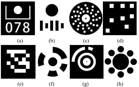
(a) (b) (c) (d)
(e) (f) (g) (h)
Figure 1. Several typical artificial coded target. (a) Caesar, 2005; (b) Wong, 1988; (c) Ahn, 2001; (d) Fraser, 1997; (e) Fiala, 2010; (f) Schneider, 1993; (g) Van Den Heuvel, 1993; (h)
Ma, 2006;
Until recently, the planar coded target commonly used in CRP contains concentric circles, circular dots and other types, shown
in Figure1. In order to correctly reconstruct the corresponding relationship between 2D image coordinates and 3D world coordinates, it is critical to accurately extracting the image coordinates of feature points (Feng et al., 2002).
To implement such procedure, large quantity work has been done. Ahn et al. (2001) proposed a circular coded target for automatic image point measurement and identification. Through all the processing stages, ellipse fitting played a significant role in recognition the dots around the central concentric ring. Cronk et al. (2006) presented the practical developments of manual and semi-automatic hybrid measurement using the red circle-based coded targets. Bethmann et al. (2010) presented a least-squares matching algorithm using the plane projective transformation model and polynomial transformations to handle geometric distortions between the images with coded targets. Fraser et al. (2009) discussed a hybrid measurement to perform semi-automatic extraction of feature points of circular dots target in order to determine image point correspondence for image matching. In addition, Luhmann (2014) discussed a feature of projective geometry which causes eccentricity in the image measurement of circular targets.
In general, a circle becomes an ellipse after projective transformation. For an ellipse, its simple geometric features and explicit mathematical expression make it easy for detection and furthermore it is not common in natural scenes. Hence, circle-based coded targets are increasingly popular in CRP. And the common algorithms to extract circle-based coded targets are mainly based on ellipse fitting.
However, due to discretization error caused by noise, illumination and shooting viewpoints, the parameters of ellipse might be incorrect when the number of pixels on eligible edges is not enough to accurately determine the shape of the ellipse. Thus the detected feature point coordinates estimated by central ellipse is unreliable and is not suitable to use for decoding the target.
In order to overcome the shortages of circle-based coded target extraction methods mentioned above, this paper presents a novel design of circle-based coded target, including feature point coordinate and feature point serial number simultaneously. This target design not only can fulfill the need of being detected and recognized accurately, but also could be located from farther distance and wider angle, especially in complex environment. Based on the features of proposed target, a comprehensive method to perform robust extraction of coded targets is introduced. The method utilizes a coarse-fine procedure: firstly, instead of using ellipse fitting, shape-based template matching is creatively applied to obtain the approximate regions of coded targets; then, center points of coded targets are determined by region growing; finally, false results are filtered by parity check.
2. METHOD
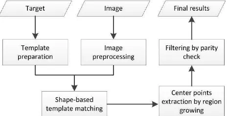
The organization of proposed method is shown in Figure 1. This method has three main stages: 1) template preparation by a set of geometric transformations based on the original target; 2) shape-based template matching; and 3) center points location shape-based on region-growing and false results removal by parity-check.
Figure 2. Flowchart of the proposed target extraction algorithm
2.1 Design of the coded target
The novel design of planar coded target is shown as follows:
Figure 3. The design of the proposed coded target
In Figure 3, there are two main parts in the designed coded target. The upper part is used for extracting the feature point coordinate, named “target box”. From outside to inside, there are four different patches, black rectangle, white ring, black outer circle and white inner circle while the center points of latter three patches are the same. Specifically, the central white circle is utilized to be located precisely by total station instrument. And the lower part of white ring is covered by a black rectangle which makes an indentation of the ring. With this creative design, the coded target can own an advantage of rotation invariance as well as offer orientation information in the step of template matching. Moreover, the shape features made by white-black patches could be identified even from a far distance and wide angle as long as
the imaging distortion is within acceptable limits. In addition, based on empirical knowledge, the concentric-circle-based shape rarely appears in natural scenes which could substantially decrease the disturbance from background.
The feature point serial number is expressed by the lower part, named “coding box”. Owing to the random location of artificial target and measurement system, it is necessary to re-identify the feature point set in order to completely match 2D target image coordinates and 3D target world coordinates. However, for most of circle-based coded target used in CRP, the coding box is commonly designed to be uniformly distributed along the circumference, which is likely to reduce the robustness of target extraction algorithm. Therefore, the target box and coding box is totally separated in our design. Meanwhile, coding box also plays a role of “check code” and could be used to remove false results to some extent. The details of this part will be introduced later. In this paper, the target is almost the half size of A4 paper and it can be scaled in equal proportion if necessary.
2.2 Template preparation
Here, templates are created based on the proposed target. However, original target will be distorted by perspective projection transformation during imaging. Thus it is essential to perform some pre-processing, as follows:
1. Use the original target box as the basis.
2. Select a region small than black rectangle but bigger than white ring and remove the central white circle.
3. Minify the result in step 2 to a designated size (according to the CRP practical application requirements, such as 100 × 100 of horizontal scaling, rotating and scaling, respectively.
Hence, we can obtain a template set, which contains almost all the possible shape features of coded targets in imaging.
2.3 Shape-based template matching
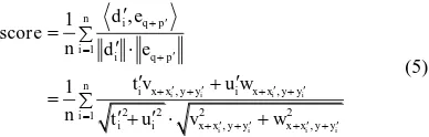
In this part, shape feature is used for template matching. In order to perform shape matching, we use a similarity measure (Steger, 2002) to make a judgment whether the two objects are similar
The direction vectors can be generated by a number of different image processing operations, e.g., edge, line, or corner extraction. The International Archives of the Photogrammetry, Remote Sensing and Spatial Information Sciences, Volume XLI-B1, 2016
The search image can be transformed into a representation in which a direction vector , ( , , , )T
x y x y x y
d v w is obtained for each
image point ( , )x y . In the matching process, a transformed template must be compared to the image at a particular location by a similarity measure. Then, we sum the normalized dot product of the direction vectors of the transformed template and the search image over all points of the template to compute a matching score at a particular point ( , )T
q x y of the image. This similarity measure is defined as follows:
1 Meanwhile, an image pyramid with 3 levels is used to speed up the matching procedure. Therefore, the detailed steps of template matching based on shape feature could be summarized as follows:
1.For each input image, a slide window with the size as same as the original template is used. The sliding step is set to the half window size. For each move, the corresponding patch of image is defined as a region of interest (ROI).
2.For each ROI, bilateral filtering (Tomasi et al., 1998) and Canny edge detection (Canny, 1986) are performed successively so as to enhance edge contour as well as reduce redundant edge points. Consequently, a set of edge points is obtained
3.Using the proposed similarity measure to compute the matching score between ROI and template set Ct.
4.Compare the score and predefined threshold Tm, if score is
greater than Tm , the characteristics of the corresponding
template and ROI will be stored.
2.4 Center points extraction
After the approximate regions of target boxes are detected by template matching, we take the region growing algorithm (Fan, 2001) to find the coordinates of candidate feature points, as follows:
1.For each candidate patch, Otsu’s adaptive method is used to perform the process of segmentation.
2.The center point of patch is served as the seed if its gray value is zero.
3.Using region growing to connect the remaining pixels one by one at the smallest scale.
After the above steps, the minimum patch including the corresponding feature point is determined. Then the coordinate
(X Yi, )i of candidate feature point is defined as:
2.5 Filtering by parity check
After the above steps, coding box can help a lot to remove false results. In this part, even check, one of parity check, is used to further eliminate false positives. As mentioned above, there are eight blocks in the coding box. Every block is assigned with two colors, black or white in row-major order and defined as number 0 or 1. Thus it can be regarded as an eight-bit binary number, i.e.
0 1 2 3 4 5 6 7
NB B B B B B B B, as shown in Figure 4.
Figure 4. Parity check for coding box
To improve the robustness, B7 is selected as check bit to identify
odd-even property while the rest are code bits, as follows:
7 0 1 2 3 4 5 6
B B B B B B B B
(7)
where is the bit-wise XOR operation.
3. RESULTS AND DISCUSSION
To verify the effectiveness of the proposed method, experiments are conducted with images in natural scenes. These images are captured from different distances, viewpoints and contain some proposed targets as well as other objects, which make the background much more complicated. The coded targets are printed by a common inkjet printer (HP P1606dn) and a Sony NEX-7 digital camera with 50mm lens is used. In addition, practice results indicate that, when the target size in imaging is range from 20 to 100 pixels, it is more advantageous to the digital image processing and the realization of the proposed algorithm.
Programming was done in C++ on a Window 7(64 bit) platform. The hardware system is an off-the-shelf computer with 4GB RAM and a dual-core 3.4 GHz CPU. Two of the experimental results are shown in Figure 5 and Figure 7. It can be seen that all the coded targets are correctly identified after applied the proposed algorithm (labelled with red crosses). Table 6 and Table 8 present the corresponding quantitative assessment of the location accuracy of feature points. Here, the ground-truth is determined by eye-measurement.
Figure 5. Identification and location of the coded targets (viewpoint: 60°)
Target ID
Proposed Ground-truth Deviation
x y x y x y
29 823.721 1384.06 824.013 1384.052 0.292 0.008
30 1013.9331687.4661013.927 1687.924 0.006 0.458
42 677.7191499.756677.963 1499.884 0.244 0.128
45 1058.8971326.0871059.007 1326.031 0.11 0.056
63 697.079 1690.52 697.045 1691.094 0.034 0.574
82 1273.6911401.5951274.016 1401.944 0.325 0.349
89 832.916 1577.311 833.024 1577.005 0.108 0.306
97 695.9781224.943695.916 1224.912 0.062 0.031
113 1035.188 1496.872 1035.019 1496.985 0.169 0.113
115 1221.256 1621.954 1221.025 1621.936 0.231 0.018
Average 0.158 0.204
Table 6. Deviation analysis of feature points localization (pixel)
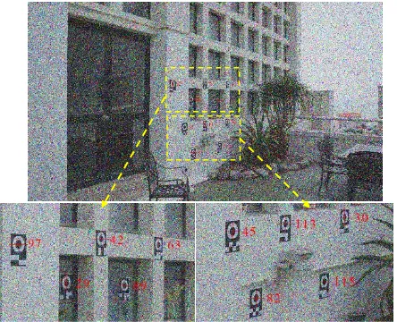
Figure 7. Identification and location of the coded targets under Gaussian noise environment (viewpoint: 60° and 100 )
Target ID
Proposed Ground-truth Deviation
x y x y x y
29 823.955 1383.691 824.013 1384.052 0.058 0.361
30 1014.3011687.0721013.927 1687.924 0.374 0.852
42 677.8161500.108677.963 1499.884 0.147 0.224
45 1058.6021325.9771059.007 1326.031 0.405 0.054
63 697.443 1691.22 697.045 1691.094 0.398 0.126
82 1274.3111401.9471274.016 1401.944 0.295 0.003
89 832.430 1577.598 833.024 1577.005 0.594 0.593
97 696.1841224.966695.916 1224.912 0.268 0.054
113 1034.93 1497.295 1035.019 1496.985 0.089 0.31
115 1220.841 1621.888 1221.025 1621.936 0.184 0.048
Average 0.281 0.262
Table 8. Deviation analysis of feature points localization under Gaussian noise environment (pixel)
As we can see, the proposed method can obtain good performance even the images are under severe perspective
distortion and noise environment. Table 6 and Table 8 show the deviation analysis of feature point’s localization. Note that the accuracy of feature points positioning could reach the sub-pixel level while its realization is relatively easy. The computing time is about 0.2 second per image when the image size is 3000 × 1688 pixels. Hence, it is qualified for real-time applications in close-range photogrammetry. In summary, we conclude that the proposed target design and the corresponding target extraction algorithm performs well and achieves acceptable results.
4. CONCLUSIONS
In this paper, a novel design of planar coded target for close-range photogrammetry and the corresponding extraction method are presented. Unlike other common circle-based coded targets, the proposed target design separates the target box and coding box totally and owns an advantage of rotation invariance. Then a coarse-fine algorithm incorporating shape-based template matching, region growing and parity check is implemented to perform robust identification and location of coded targets in natural environment. Meanwhile, the proposed method could handle variance of shooting distance and viewpoints and overcome the interference of perspective distortion and noise to some extent. Our algorithm is demonstrated useful and reliable through experiments. Future improvements will focus on optimizing the algorithm to reduce computing time and improve the robustness.
ACKNOWLEDGEMENTS
This research is partly supported by the National Natural Science Foundation of China (Project No. 61371144).
REFERENCES
Ahn S.J., Rauh W. and Kim S.I., 2001. Circular coded target for automation of optical 3D-measurement and camera calibration,
International Journal of Pattern Recognition and Artificial
Intelligence, vol. 15, no. 06, pp. 905-919.
Bethmann F. and Luhmann T., 2010. Least-squares matching with advanced geometric transformation models, ISPRS International Archives of Photogrammetry, Remote Sensing and
Spatial Information Sciences, Vol. XXXVIII, Part 5, pp. 57-69.
Canny J., 1986. A computational approach to edge detection,
IEEE Trans. Pattern Analysis and Machine Intelligence, no. 6,
pp. 679-698.
Caesar T., and Michaelis M., 2005. Reference mark, method for recognizing reference marks and method for object measuring, Google Patents.
Cronk S., Fraser C.S. and Hanley H., 2006. Hybrid measurement scenarios in automated close-range photogrammetry, ISPRS International Archives of Photogrammetry, Remote Sensing and
Spatial Information Sciences, Vol. XXXVII, Part B3b, pp.
745-749.
Fan J., Yau D.K. and Elmagarmid A.K., 2001. Automatic image segmentation by integrating color-edge extraction and seeded region growing, IEEE Trans. Image Processing, vol. 10, no. 10, pp. 1454-1466.
Feng W., 2002. Close Range Photogrammetry, Wuhan University Press, pp. 125–130.
Fiala M., 2010. Designing highly reliable fiducial markers, IEEE
Trans. Pattern Analysis & Machine Intelligence, vol. 32, no. 7,
pp. 1317-1324.
Fraser C.S., 1997. Automation in digital close range photogrammetry, First Trans Tasmin Surveyors Conference, pp. 12-18.
Fraser C.S. and Cronk S., 2009. A hybrid measurement approach for close-range photogrammetry, ISPRS Journal of
Photogrammetry & Remote Sensing, vol. 64, no. 3, pp. 328-333.
Luhmann T., 2010. Close range photogrammetry for industrial applications, ISPRS Journal of Photogrammetry & Remote
Sensing, vol. 65, no. 6, pp. 558-569.
Luhmann T., 2014. Eccentricity in Images of Circular and Spherical Targets and its Impact to 3D Object Reconstruction,
ISPRS International Archives of the Photogrammetry, Remote
Sensing and Spatial Information Sciences, vol. xl-5, pp. 363-370.
Ma Y., Zhong Y. and Dai X., 2006. A method for 3D scanning and reconstruction based on coded points, Optical Technique, vol. 32, no. 06, pp. 865-868.
Schneider C. and Sinnreich K., 1993. Optical 3-D measurement systems for quality control in industry, ISPRS International
Archives of Photogrammetry and Remote Sensing, vol. 29, pp.
56-59.
Steger C., 2002. Occlusion, clutter, and illumination invariant object recognition, ISPRS International Archives of Photogrammetry, Remote Sensing and Spatial Information
Sciences, vol. 34, no. 3/A, pp. 345-350.
Tomasi C. and R. Manduchi, 1998. Bilateral filtering for gray and color images, in Proc. IEEE Conf. Computer Vision, pp. 839-846.
Van Den Heuvel F.A., Kroon R. and Le Poole R.S., 1993. Digital close-range photogrammetry using artificial targets, ISPRS
International Archives of Photogrammetry and Remote Sensing,
vol. 29, pp. 222-229.
Wong K.W., Lew M. and Wiley A.G., 1988. 3D metric vision for engineering construction, ISPRS International Archives of
Photogrammetry and Remote Sensing, vol. 27, no. B5, pp.
647-656.