TOWARDS RECONSTRUCTING A DORIC COLUMN IN A VIRTUAL CONSTRUCTION
SITE
D. Bartzis
National Technical University of Athens, School of Architecture, Patision Str. 42, 106 82, Athens, Greece [email protected]
Commission II
KEY WORDS: Doric order, Doric column, architectural member, 3D reconstruction, point clouds comparison, ICP algorithm
ABSTRACT:
This paper deals with the 3D reconstruction of ancient Greek architectural members, especially with the element of the Doric column. The case study for this project is the Choragic monument of Nicias on the South Slope of the Athenian Acropolis, from which a column drum, two capitals and smaller fragments are preserved.
The first goal of this paper is to present some benefits of using 3D reconstruction methods not only in documentation but also in understanding of ancient Greek architectural members. The second goal is to take advantage of the produced point clouds. By using the Cloud Compare software, comparisons are made between the actual architectural members and an “ideal” point cloud of the whole column in its original form. Seeking for probable overlaps between the two point clouds could assist in estimating the original position of each member/fragment on the column. This method is expanded with more comparisons between the reference column model and other members/fragments around the Acropolis, which may have not yet been ascribed to the monument of Nicias.
1. INTRODUCTION
1.1 The Doric column
Of all the elements of ancient Greek architecture, the Doric column is probably the most representative. By “traditional means” a complete architectural documentation of a Doric column is challenging, due to the characteristics of this element.
A typical column is in most cases made of a series of drums (spondyloi), placed one on top of the other until the desired height, after which follows the capital. The pillar’s diameter is not the same throughout; it gradually reduces towards the top. In some cases at about 2/5 of the total height the column’s diameter may be reach a peak before reducing again with a normal rate. This is called entasis, and whenever noticed, the edges of the pillar are not straight lines, but curves, e.g. branches of hyperbolas. The last feature of a Doric column is the flutes. Each diameter normally has 20 flutes, with their profile being usually a composite curve made of three arcs of circle. However this profile may change along the way on top, both in terms of width and curvature.
The features mentioned above show not only how intricate it was to build and carve the final surfaces of a Doric column, but also how challenging it is to measure and draw them today, especially if they are severely damaged through the centuries. In many cases the edges of the flutes (the arises) are broken, meaning that only the inner diameter could be sufficiently measured, while the outer should be calculated by spotting the best preserved flute (Korres 1989, p. 14). The same difficulties occur when trying to extract the flute’s profile. The whole process requires plenty of time, dedication and in some instances the accuracy may not be the optimal. The final products would be 2D drawings of the upper and lower edge of each drum and elevations. Those drawings would be the basis
for all combinations of members/fragments, so that a column could be restored on paper. The actual combination of fragments may require a fully equipped crew, with lifting devices, crowbars and plenty of time. What if the members weighed tones and were scattered far from each other?
3D reconstruction methods, involving 3D Laser Scanning Methods or Image Based Methods could provide solutions to these problems, as they completely digitize the geometry of architectural members by producing point clouds (Evgenikou, Georgopoulos 2015), meaning that probable combinations of members/fragments could be investigated in a software environment, in a “virtual anastylosis construction site”.
1.2 Case study: The Choragic monument of Nicias
around the Acropolis. New probable fragments/members from the monument have been discovered in the recent years, but no attempt was made, to securely ascribe them to the monument of Nicias.
During the research for my dissertation, many marble fragments drew my attention, because they could belong to the monument of Nicias. Measuring and drawing by hand every probable candidate would be a fruitless task, especially if it was proven not to be a part of the monument. So another solution should be elaborated for the purposes of my research, which would at the same time evolve the use of photogrammetry beyond a simple 3D documentation.
2. METHODOLOGY
2.1 Suggested approach
The extraordinary thing in ancient Greek architectural orders is that someone could reconstruct basic elements by having only a small fragment in hand, required that it preserves some crucial features. Intact architectural members, combined with representative fragments can probably result in a complete restoration of a building’s order. That is the case with the monument of Nicias.
The almost intact foundations and a variety of architectural members from all its structural elements have resulted in a very accurate reconstruction of the building. The element of the Doric column is almost completely known as well. The column height is related to that of the cella walls and is estimated at 5.102 m (Dinsmoor 1950, p.339). The lower and upper diameters are known as well, by the available architectural members. So it is very easy to create an “ideal” 3D model of a column, which matches the features of the original ones in their “as built in antiquity” state of preservation.
The 3D reconstruction of the building’s known architectural members ensures the extraction of accurate flute profiles and a certain calculation of the upper and lower diameters, so that the element of the Doric column could be simulated in the best possible way. This would be proved by checking if the point clouds of the available architectural members match with parts of geometry of the “ideal” column element.
2.2 3D reconstruction of architectural members
2.2.1 3D reconstruction of Doric column drum and capital from the Nicias monument
The architectural members on the site were the lower column drum and two capitals, the one being in an excellent state of preservation, so it was preferred for 3D reconstruction. The photogrammetric survey of these members was carried out in July 2016 by means provided by the NTUA Laboratory of Photogrammetry and by the guidance of Prof. Andreas Georgopoulos.
Control points were placed on each member covering all sides, along with other survey markers placed around them as extra reference points. Seven control points were placed on the Doric capital and ten on the column drum. The points’ coordinates were surveyed with a total station.
Photo shooting was carried out using a full frame DSLR camera, Canon EOS 1Ds Mark III, with 21MP sensor (5616X3744 pix). Each member was photographed by different angles. It took 59 shots for the Doric capital and 62 for the column drum, using both 50mm and 24mm prime lenses.
The data was processed in the NTUA Laboratory of Photogrammetry with Agisoft PhotoScan Professional 1.2.5 software, which generated dense point clouds of each architectural member (Capital: 14 million points, high quality. Drum: 25 million points, high quality) (Figure 1).
Figure 1.Doric capital and bottom column drum, which belong to the Nicias Monument. Point clouds produced with Agisoft
PhotoScan®
2.2.2 3D reconstruction of non-assigned architectural members to the monument of Nicias
During my ongoing research I have found a column drum on the north slope of the Acropolis (Figure 2). I have decided that this architectural member along with two fragments located at the site of the Nicias monument, would be the examples for this case study, in the role of probable candidates belonging originally to the building.
members I have used a Nikon d5300, DSLR camera with CMOS censor 24 MP (6000X4000 pix) and a prime lens 50mm. The data was processed with Agisoft PhotoScan Professional 1.2.5 software.
Figure 2.Doric column drum, found on the north slope of Acropolis. Point cloud produced with Agisoft PhotoScan®
Figure 3.Fragments of Doric column drum, found at the site of Nicias monument. Control points were used as scale bars in
Agisoft PhotoScan®
2.3 Reconstruction of the “ideal” column
With Agisoft PhotoScan I produced textured 3D models of the column drum and capital, from which I extracted a complete set of orthophotos from each of the sides. Additionally I have made horizontal and vertical sections on the column drum, in order to have a better depiction of its profiles and outline, without any other unneeded details.
After inserting the orthophotos in AutoCAD I have begun the tracing process, in order to justify specific geometric features of the column.
2.3.1 The geometry of the flutes
The first observation, deriving from the orthophotos, was that the flutes of the column drum had a simple profile, being arcs of circle with an angle of ca 60o, whereas usually in other monuments it is a tri-centric arc or an ellipse (Scahill 2012, pp. 99-100). This is an additional confirmation that the Nicias monument has many influences from the Propylaia of the Athenian Acropolis (Dinsmoor 1919, p. 462), where the Doric columns also have flutes made of circle arcs (Dinsmoor & Dinsmoor Jr 2004, p. 98), along with other architectural features.
2.3.2 Calculation of lower and top diameters of the column
Having ensured that the flute profile is actually an arc of a circle, I have decided to reconstruct each flute of the drum by picking three points, one approximately in the middle and the others as close as possible to the preserved surfaces near the arises. This was an important task, as the points had to be picked carefully, representing only initial surfaces of the marble, not destroyed. Those points created the circle, part of which formed the flute profile. The intersection of two neighboring circles recreated the form of the broken arise between two flutes. Doing this I was able of measuring all ten outer diameters of the bottom and top of the column shaft. The inner diameters were measured as well in AutoCAD (Figure 4).
The twenty circles drawn as well as the ten outer and inner diameters had slight variations, so I took the medium for each parameter (radius of circle, arc angle, chord length, outer diameter, inner diameter of column).
The last step was to create a polygon with twenty equal edges, inscribed in the outer diameter calculated above (one for the bottom and another for the top) (Figure 4). On each edge of the polygon I have drawn the flute according to the medium parameters. Thus I have reconstructed the horizontal sections of the column’s top and bottom, which remarkably correspond to the initial orthophotos, when placed one on top the other.
Figure 4.Left and middle: Tracing of flutes on the lower and upper diameter of the column, measuring of inner diameters (blue lines) and reconstruction of outer diameter (red lines). Right: Reconstruction of the column shaft using the medium
parameters from all measurements.
2.3.3 Entasis of the column shaft
known. The only thing to be examined was if the column shaft had entasis.
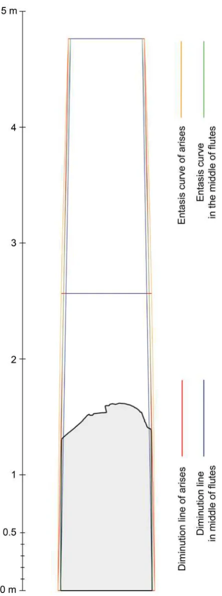
Figure 5.Section of the column drum along the axis crossing the middle of two diametrical flutes, which shows that the diminution line is not followed. Instead it corresponds with the proposed entasis curve.
In AutoCAD I have traced a vertical section of the drum, made exactly on an axis crossing the middle of two diametrically facing flutes. I have picked those preserved at the maximum available height, having at the same time their initial smooth surfaces, for more accurate results. The traced line of the section did not correspond with the diminution line (Figure 5) and this is solid evidence that the columns of the Nicias monument had entasis.
The evident relation of the Nicias monument to the Athenian Propylaia made me assume, that the entasis maximum would occur somewhere along the middle of the column shaft, at the 7/13 of the height be exact. After a series of experiments with the value of the entasis peak, I have concluded that the optimum was 2.05 cm at 2.56 m from the bottom of the column shaft. The entasis curve is commonly a hyperbola, but it can be simulated accurately with the form of a circle with 137.78 m radius. That is 1/250 of the column shaft’s height, or 1/41 of the lower diameter. The suggested arc of circle remarkably follows the traced lines of the vertical section of the column drum (Figure 5), given that Dinsmoor’s calculation of the total height is correct.
2.3.4 Reconstruction of the ideal column model in AutoCAD
The most intricate part of the ideal column to be reconstructed in 3D was the changing profile of each flute, which followed the curve of the entasis. Having the flute profiles of the bottom and top and also the entasis curves as guides, the “EDGESURF” command in AutoCAD produced a very satisfying and accurate result (Figure 6). The model has been exported in FBX format for further use later in Cloud Compare software.
2.4 Comparisons between point clouds of architectural members and the “ideal” column model
The concept of finding probable overlaps of point clouds from architectural members/fragments with an ideal model, made Cloud Compare a good software to begin with. Besides being free-ware, it is has a relatively user friendly environment, with basic functions, which fit with the needs of this case study. I have imported the ideal column model as FBX file in Cloud Compare and have converted it to point cloud by sampling the mesh (1 million points/square unit).
2.4.1 Initial comparison: Nicias column drum point cloud with the “ideal” column model
The first and most crucial comparison of the ideal column is with the column drum that belongs to the Nicias monument, which has also provided valuable data for the reconstruction. The “ideal” column is set as “Model”, meaning it is the reference cloud, whereas the architectural members are set as “Data”, meaning that they are the ones moving and rotating in order to match the reference cloud.
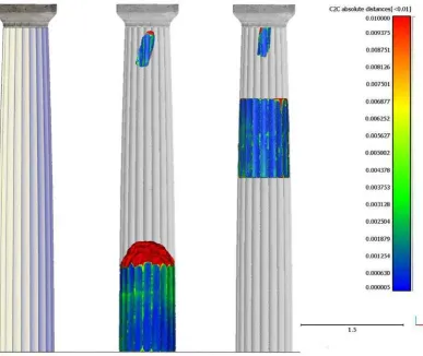
Figure 6.Left: The 3D model of the “ideal” column shaft, with the Doric capital placed on top of it. Middle: In Cloud Compare® software Fine Registration (ICP) of ideal model with the lower column drum and one of the fragments. The colour scale represents distances between the point clouds. Note that the broken arises are shown with green colour. Right: Fine Registration (ICP) of a fragment and the column drum from north of the Acropolis with the ideal model, which shows their original position on the column shaft.
The process came to a success only after I have implemented the calculation of distance of points between point clouds, choosing to not consider far points. After that, in the “Fine Registration ICP” preferences, scalar fields can be used as criterion of matching points. At the same time I have excluded from the comparison the distant points. The sample limit was set at 750000 points. The final registration of the column drum in relation to the ideal model was satisfactory. I have repeat the “Distance between point clouds” and the longest distances recorded on the new scalar field were focused on the broken arises of the flutes (Figure 6).
2.4.2 Assigning other architectural members to the Doric columns of the Nicias monument
The exact same process described above has been followed for the column drum found north of the Acropolis. Manual alignment of the point clouds was equally easy and it was evident from this stage of the process that the drum was the semifinal to the top. Fine Registration optimized the results. So strictly in terms of geometric features the column drum could be ascribed to the monument of Nicias.
The process with the remaining two fragments did not prove to be easy at all, as manual alignment was more intricate and the only guide to estimate the initial position on the column was the width of the flute. The Fine Registration ICP algorithm
produced many times wrong results, a fact that points out how crucial the manual alignment is for the whole process. Maybe in another program or a specialized algorithm for similar purposes could speed up the process and even minimize manual overlap of point clouds.
After several attempts and experimentation the fragments found their positions on the ideal column model, meaning that from the aspect of geometric features they could be assigned to the monument of Nicias. I should mention here that by finding their position I mean their exact height along one flute. To find exactly which flute it was, out of the twenty, I have to closely and very carefully observe each fragment and search for specific criteria, such as weathering of surfaces etc. (Korres 1989, p. 22).
3. CONCLUDING REMARKS
invaluable to have knowledge of other similar monuments, which would provide a feedback of information deriving from comparisons, relations etc.
As for the methodological approach suggested in this paper, the main concept could be radically upgraded by the aid of other software and with more sophisticated algorithms, which however go far beyond my capabilities as an architect.
Such an improved process (automated or semi-automated), could have an advantage in saving time and effort. For example, after spotting a suspicious fragment, probably hundreds of meters away from an ancient monument, one could quickly create a 3D model, even by simple means of manually measured control points instead of necessarily using total station, and then generate a point cloud. This could be instantly compared to the “ideal” column element or even to the already ascribed architectural members, so that it could be determined if this fragment could have ever been part of this monument. Of course there are a handful of other criteria which define the assignment of an architectural member to a monument, but it is hoped, that at least with this proposed method, this process would be quicker when it comes to geometry comparisons.
The same process made by ‘traditional means” would require countless hours of work for measurements and production of drawings, which still they would carry only 2D information. The suggested method presented in this paper could speed up the architectural documentation of ancient Greek buildings, especially when they involves the intricate geometry of hundreds column drum fragments, which in some cases are almost impossible to define their original position on the pillar. In addition fragments that are assigned to close positions with each other could be tested for probable matching together, using software, without the need of actually moving and lifting the architectural members in the real world. This would be a great advantage for anastylosis projects, as separate parts or even the whole project could be simulated in the virtual world, before final implementation on site (Thuswalder B., Flöry S., Kalasek R., Hofer. M., Huang Q., Thür H., 2009), giving enough time for review by the scientific community.
As a last comment, I hope it became obvious from this paper that dealing with ancient monuments is an effort with many demands: On the one hand deep knowledge of the monument and its context, experience in architectural history, acute observation of details and on the other, deep knowledge in photogrammetry, experience in using a series of software or having programming skills. With the rapid advance in all the fields mentioned above, the interdisciplinary approach is mandatory, as in such cases the best possible results derive from team effort.
ACKNOWLEDGEMENTS
I would like to express my gratitude to professor NTUA Andreas Georgopoulos for all his guidance during the project and for his kind generosity in sharing not only knowledge with me, but also by providing me all the necessary surveying equipment and access to the Laboratory of Photogrammetry for processing the collected data. I would also like to thank Vasileios Psomas and Katia Demagou, students at the Rural and Surveying School of Engineering NTUA for their assistance in the fieldwork. I am also indebted to archaeologist Efi Kassapoglou, the overseer of the Nicias monument for
granting us permission by the Ephoria of Athens in order to survey the architectural members. I would also like to thank my PhD supervisor Manolis Korres and the Eygenides Foundation, which generously funded my research with a fellowship award for the academic year 2016/2017.
REFERENCES
Dinsmoor W.B & Dinsmoor W.B Jr, 2004. The Prorylaia to the
Athenian Akropolis, voll 2: The Classical building, The
American School of Classical Studies at Athens, Princeton NJ, USA
Dinsmoor W.B., 1950. The architecture of ancient Greece, an
account of its historic development, Biblo & Tannen, London
UK
Dinsmoor W.B., 1910. The Choragic Monument of Nicias,
American Journal of Archaeology, 14 (4), pp.459-484
Evgenikou V., Georgopoulos, A., 2015. Investigating 3d reconstruction methods for small artifacts. ISPRS Archives, Volume XL-5/W4, pp. 101-108, WG V/4, CIPA - 3D-Arch 2015 – 3D Virtual Recon-struction and Visualization of Complex Architectures 25–27 February 2015, Avila, Spain. Edi-tor(s): D. Gonzalez-Aguilera, F. Remondino, J. Boehm, T. Kersten, and T. Fuse. http://www.int-arch-photogramm-remote- sens-spatial-inf-sci.net/XL-5-W4/101/2015/isprsarchives-XL-5-W4-101-2015.pdf
Korres M., 1989. Study for the restoration of the Parthenon vol
2a, Ministry of Culture, Committee for the Preservation of the
Acropolis Monuments, Athens, Greece
Scahill D. 2012. The South Stoa at Corinth, design,
construction and function of the Greek phase, PhD dissertation,
University of Bath
Thuswalder B., Flöry S., Kalasek R., Hofer. M., Huang Q., Thür H., 2009. Digital Anastylosis of the Octagon in Ephesos.
Journal on computing and cultural heritage (JOCCH), 1 (2)
Vitti P., 2016. Survey of historical heritage in the era of computers: A matter of aim and methodology. Honorary
Volume for Professor Manolis Korres, Melissa Publishing