Summary We report on the design and performance of a system that speeds measurement of radial tree-ring increments on tree stem disks; this method replaces the usual binocular microscope with a video image, and automates the measuring and recording processes. The system was used to measure bole sections cut from stems at various heights to determine volume growth of representative trees in an old-growth ponderosa pine stand. The objective of the measurement system was to speed acquisition of annual growth increments from a large number of disks. A personal computer controls the location of a video camera in a 3-axis positioning system. The operator views the sample on a video monitor and positions the camera over each ring by selecting it with a computer-driven mouse. The com-puter measures and records the distance that the camera moves between each ring. Task selection is facilitated by menu-driven software that also formats, checks and organizes data files. Measurements have a resolution of 0.026 mm; however, finer resolution could be obtained with a different camera lens. Tests of measurement variability (repeated measurements by indi-vidual operators on a single radius) indicated standard errors of 0.006 mm or less for the first measurement sets for four operators. Correlation coefficients among four radii per bole section were as low as 0.66 for a whole tree, suggesting that measurements on single radii may provide poor estimates of radial growth for old trees. This system also offers the potential for automatic ring detection and measurement.
Keywords: dendrochronology, radial increment, stem analysis, tree-ring measurement.
Introduction
Dating of tree rings and measuring the amount of radial growth have long been of interest to foresters and ecologists. The study of tree rings is becoming increasingly important not only for dating individual trees and climatic events affecting tree and forest stand development, but also for studying the growth response of trees to environmental variables such as fire, insect attack, global warming, increased concentrations of atmos-pheric CO2, and atmospheric pollution. In the standard method of measuring ring widths, an observer uses a binocular
micro-scope to examine an increment core mounted on a holder. Rings are located with a pointer, and the location of each ring is recorded by a computer when triggered by the observer (Fayle et al. 1983, Jordan and Ballance 1983, Clyde and Titus 1987, Schweingruber 1988).
A study of the development of old-growth features of pon-derosa pine trees required measuring growth increments on multiple radii of bole sections cut at various heights on 24 sample trees (Kaufmann 1996). Trees ranged between 68 and 84 cm in diameter and between 180 to more than 400 years in age. We envisioned a system that would work with bole cross sections in addition to increment cores, and that would speed and aid measurements by (1) eliminating the need for a micro-scope, (2) positioning the pointer to the next ring automat-ically, (3) awaiting operator approval or editing before recording each ring position, and (4) creating data files auto-matically. For our purposes, an ideal system would accommo-date bole cross sections approaching one meter in diameter and would also work effectively with moderate variations in disk thickness. We also needed correct dating of each annual ring to ensure that radial growth was assigned to the proper year.
Application of video vision and image analysis to dendro-chronology has progressed rapidly in the last decade because of improvements in hardware components and a decrease in their expense. Two recent examples illustrate major differ-ences in approaching the design of these measuring systems. To replace a scanning microdensitometer, Thetford et al. (1991) designed a system that digitizes sample images on an X-ray negative. This system requires microtoming samples from a specimen core. Small ring widths (0.06 mm) are meas-urable with a video camera and microscope. In contrast, Guay et al. (1992) used a line-scan camera to build an image directly from the sanded core or disk specimen. The entire sample image is stored before interactive analysis. The practical limit of resolution was six rings per millimeter (0.17 mm ring width) for the contrast range of conifer rings, though efforts to im-prove resolution continue.
Considering the objectives of the old-growth ponderosa pine study, neither of the above systems were well-suited for simply estimating annual growth increments. Furthermore, the X-ray technique requires considerable sample preparation time and
Measuring tree-ring increments on tree bole sections with a
video-based robotic positioner
R. A. SCHMIDT,
1MERRILL R. KAUFMANN,
1,2LAURIE PORTH
1and ROSS K. WATKINS
11
USDA Forest Service, Rocky Mountain Forest and Range Experiment Station, Fort Collins, CO 80526, USA 2
Corresponding author
Received February 22, 1996
the line-scan technique requires extensive image storage media and analysis time. When we began our design (1992), neither system provided completely automatic, error-free measure-ments without operator interaction. For our study and many others using dendrochronology in various fields (e.g., review by Loaiciga et al. 1993), there is need for an accurate measure of growth increment on many samples rather than details of the cell structure within annual rings. A fully or nearly automatic method is desired, though such a system may never be suffi-ciently reliable.
This paper reports the design and operating characteristics of a video-based system for measuring radial growth incre-ments on bole sections. Once the hardware was assembled and initial software programing was completed, the system under-went significant software improvements. The resulting system reported here has made more than 150,000 radial increment measurements on a total of approximately 240 bole cross sections (Kaufmann 1996). Although the system did not attain the goal of being fully automatic for ring measurement for ponderosa pine samples, it may have that capability if certain sample criteria are met. This paper describes the design, per-formance, and cost effectiveness of this system designed to speed measurements on tree rings of bole sections.
Design
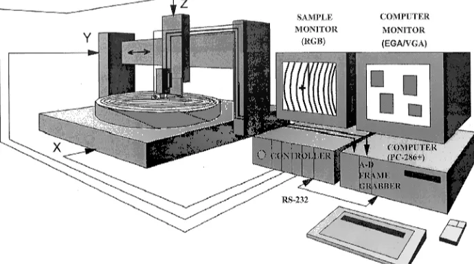
An overview (Figure 1) of the system helps define the subsys-tems described below. The locator subsystem includes a gantry for holding the specimen and camera, and software for moving the camera in horizontal (X--Y) directions. The autofocus subsystem controls camera distance from the sample along the vertical axis (Z). The vision subsystem transfers a video cam-era image of the sample to a cathode ray tube monitor. Total system cost for the hardware and software was approximately US$15,000 in 1992.
All programing is in QuickBasic (Microsoft Corp.), except for the assembly language code used by the microprocessor
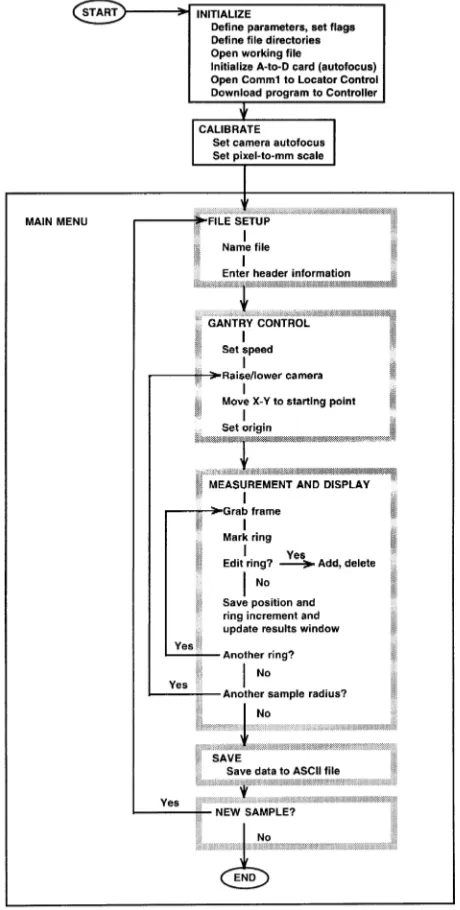
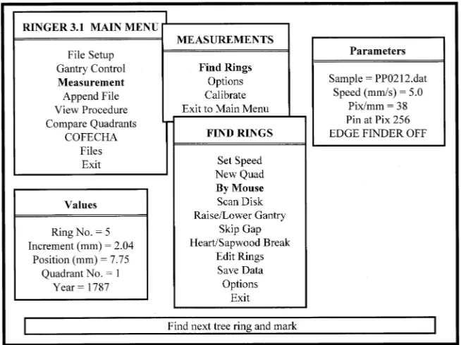
which controls the locator subsystem. (The use of this and all trade and company names is for the benefit of the reader; such use does not constitute an official endorsement or approval of any service or product by the U.S. Department of Agriculture to the exclusion of others that may be suitable.) A flow diagram for the system software is shown in Figure 2. The design uses menus to obtain operator input (Figure 3). Items within menus may generate sub-menus for additional input. This approach was quickly and easily implemented by the several operators. (The subroutines could be incorporated into a Microsoft Win-dows programing environment.)
Vision subsystem
The components of the vision subsystem are the video camera, frame grabber, and sample monitor. A black and white video camera (Sony model WV-BL200), fitted with a 12.5 mm lens on a 9-mm extension tube, produces a sample view of 1.5 cm on the horizontal axis of the monitor. The camera sensor has 570 pixels on the same axis, giving 38 pixels per mm, or a resolution of 0.026 mm, which is similar to the resolution of the line-scan system (Guay et al. 1992). This resolution was useful for the ring widths encountered in our study. For studies involving smaller growth increments, higher resolution might be obtained with a lens of different focal length and with a more sophisticated sample lighting system. A printed circuit (frame-grabber) digitizes the camera signal for display on the sample monitor. The monitor (Magnavox model 1CM135) generates color images using red, green and blue (RGB) input signals from the frame grabber (InSync Technologies, Inc., Oakland, CA, Model EV-681). Special software enables the computer to overlay color images on the gray scale image of the sample. An attachment built onto the camera body holds a pin pointer and two small light bulbs (No. 46) near the surface of the sample. The pin pointer is useful for visual reference but is not necessary for measurements.
Components of the vision subsystem facilitate use of a proprietary software package provided by Industrial
tion Systems, Inc. (Allison Park, PA). Their Machine Vision Library is a collection of Microsoft QuickBasic subroutines designed for video inspection of parts and other applications. In contrast to most imaging software packages, these program modules are optimized for performance speed in assembly line situations and are well-suited for rapid tree ring measurements. This system is operated with an electronic mark (at the end of the pin pointer) positioned at a starting point or the last measured ring. The next ring on the sample is then marked on the monitor either by selection by the operator with a cursor, or automatically from the gray-scale profile. The ring incre-ment is computed from the number of pixels between the pin pointer and the next ring mark using the pixels-per-mm cali-bration. The value is saved by ring number in a random-access
file, and the gantry controller is commanded to move the distance required to place the pin pointer over the next marked ring. By keeping measurements near the center of the screen, distortion errors are reduced.
Each measured ring is marked on screen by a colored tick which allows the operator to check for rings that may have been missed or inaccurately located. Editing subroutines repo-sition the pin pointer at a ring mark to be moved or deleted, or at the mark before a ring to be added. The random-access working file is adjusted accordingly. Automatic ring detection involves real-time analysis of the gray-scale profile along the sample. We have used automatic ring detection experimentally, but have not yet attempted to resolve difficulties with resin ducts or other darkened areas being observed falsely as rings.
Locator subsystem
Each axis of the robotic positioner is controlled by a stepper motor. Commands to the motor drivers in the controller box are generated by a microprocessor linked to the computer by a serial interface (RS-232). The locator subsystem was pur-chased from Techno-isel (New Hyde Park, NY). The XYZ gantry system provides X-travel of 1 m, Y-travel of 0.5 m, and Z-travel of 0.3 m. Specified repeatability of location is ± 0.01 mm, with a resolution of 0.005 mm, using lead screws with 2-mm pitch and the MAC200 controller. Once the assem-bly-language program is downloaded from the computer to the controller, commands to the controller are character strings indicating axis, direction, distance and speed of movement. Acceleration ramping and testing for limit switch status are handled by the controller microprocessor.
Autofocus subsystem
Distance from the camera to the sample is measured by a linear potentiometer that senses the position of a lever arm riding on the sample surface just outside the camera’s field of view. An analog-to-digital converter (Keithley Model DAS-8) provides the computer with numbers corresponding to the voltage on the potentiometer. The computer reads the voltage on the linear potentiometer after each move along the sample, and adjusts the Z-axis stepper motor to maintain the focus distance in-itially set by the operator.
System performance
Operator procedures
Measurements were made on bole cross sections that were air-dried while stacked and weighted (to keep the disks rela-tively flat). Two air-dry diameters inside the bark were com-pared with diameters measured on fresh disks to determine the percent shrinkage; this permitted measurements of radial in-crement on air-dried or live sections.
Sample preparation of the air-dried disks for measurement of tree rings with the video system was critical. Four radii for increment measurements were selected as close to 90° from each other as possible while avoiding areas in which annual rings were distorted by branches, disrupted by drying cracks,
or damaged in other ways. Occasionally, only three or two radii were available for measurements on a disk, but in most cases four radii were usable. Surfaces were prepared by planing and sanding. To remove all evidence of the initial saw cut creating the disk, several passes were made with an electric planer, followed by sanding with a belt sander to a grit size of 180 or 220. This grit size proved adequate for most measurements. Occasionally finish sanding with finer grits was required to identify faint or missing rings.
Although measurements can be made immediately after surface preparation, we have learned that examination and manual ring counting on at least one quadrant is valuable for obtaining high-quality data, and for making the editing process more efficient. Manual marking of rings at 10-year intervals allowed direct evaluation of ‘‘marker’’ years and cross-match-ing of rcross-match-ing patterns among radii and among trees (crossdatcross-match-ing). Work with many samples from several trees results in a master chronology that helps the operator identify the faint or missing rings of any given radius. Although crossdating could be done on each radius, we chose to use an editing program comparing the four radii for each disk (see below). Manually examining rings determined the pith year for each disk. Thus the volume growth calculations for each year, using multiple radial incre-ments for each disk and multiple disks for each tree, have minimal error associated with assigning a growth increment to a wrong year.
Placement on the system Disks up to about 70 cm in diameter were placed on the gantry table intact, and disks larger than 70 cm were segmented carefully into four quadrants. Disks were held in place by positioning them on a board with sharp screws pointed upward. When the upper disk surface was not level because of unequal thickness, shims were placed beneath por-tions of the disk to level the surface adequately for camera
focusing. Experience indicated that sample shifting was unde-tectable. In some cases, disks had moderate to severe heartrot and required carefull glueing to a backing board before sanding to permit measurements of as many intact rings as possible.
File header input After positioning the disk on the gantry table (the first radius to be measured is aligned with the long axis of the table), measurements of annual increment begin with a file setup menu in which tree and disk identification is entered along with name of the operator, date, green and air-dry disk diameters, and notes. Following this, the radius number is entered, the camera is positioned at the center of the pith for the beginning of ring measuring, and rings are measured by selection with a cursor as described above.
During measurements of rings, the operator checks that ring numbers determined by manual ring counting or crossdating coincide with those measured with the video system (see Values window in Figure 3). For the first radius, any detection difficulties resulting from missing rings or narrow or faint rings are eliminated because manually placed marks are found every 10 years on the first quadrant, and faint or missing rings are identified. For the second, third, and fourth quadrants, the operator can generally detect if marker rings coincide with appropriate ring numbers displayed on the monitor, but sub-sequent editing is usually required.
Editing of quadrant data It is often useful to compare radial growth increments of all radii with a radius comparison sub-routine that displays histographs of the four radii simultane-ously. Marker years are expected to occur on identical ring numbers (and years), and discrepancies usually can be located and corrected. If necessary, binocular examination of sections of radii is done to clarify if rings are faint or missing. A more rigorous test of appropriate dating of the rings is done with a statistical package that examines cross-correlation among the
radii (COFECHA, Holmes 1983 and unpublished improve-ments). This program, used separately from the measuring software, provides a final test for the data and yields a cross-dated radial increment data set for entire trees and groups of trees with virtually no error. We used both methods of error detection and editing.
Measurement repeatability
At an early stage of system development, four different opera-tors made two successive sets of measurements on a single bole section radius. This test was conducted to determine the variability of repeat measurements both for a single operator and among operators using a single sample radius that had not been moved. The radius had 177 annual rings in a total radius length of about 325 mm, and annual radial increments ranged from about 0.5 to 4.5 mm. Mean square errors for the compari-son of two runs by each operator ranged from 0.00216 (Fig-ure 4) to 0.00623 mm, the latter occurring for an inexperienced operator. Comparisons among the first runs for all operators using a repeated measures analysis indicated a mean square error of < 0.000005 mm, and plots of accumulated radial growth for the four operators were almost indistinguishable (Figure 5, top). The maximum difference among operators for any single increment was 0.67 mm; all other differences were less than 0.37 mm, and 75 percent of the maximum differences among four operators were less than 0.17 mm (Figure 5, bottom). However, the errors were not cumulative; the system measures distances relative to a set origin at the tree pith, and an error in one ring is offset in the next as the previous total radius is carried forward for calculation. These results indicate extremely low errors associated with the operator or hardware and suggest that the combined hardware, software, and
inter-preted components produce minimal uncertainty in the meas-urements even for inexperienced operators.
Sample processing and measurement speed
Our experience indicates that processing and measuring 10 disks sampled along the bole of a large (75 cm diameter) tree can be completed in about 22 h when the worker is experienced at each step. Starting with dried disks, about three hours are required per tree for planing and rough sanding (60 grit) two diameters; an additional three hours are needed for fine sand-ing (180 or 220 grit). Manual crossdatsand-ing and marksand-ing rsand-ings of one radius per disk requires about two hours, for a total of eight hours of sample preparation time. Ring counting and editing with histographs within the software package requires less than one hour for smaller disks and up to two hours for large disks (longer for difficult disks), for a total of about 12 hours for a whole tree. Additional editing with COFECHA requires about two hours per tree, unless disks must be examined closely with a binocular scope to resolve difficulties. The resulting data set includes carefully crossdated radial incre-ment data for four radii on each of 10 disks per tree. These results apply to large trees with many annual rings. For smaller trees or trees with faster growth, both the sample preparation and measurement times would be considerably less. Fine
sand-Figure 4. Comparison of radial increment measurements for two runs by a single experienced operator. Mean square error of all paired measurements on the same ring from two runs was 0.00216 mm. Inexperienced operators had mean square errors up to 0.00623 mm, which is still a very low error.
ing would not be required for trees with large radial incre-ments, and most editing would be unnecessary where small or missing rings do not occur.
Single or multiple radii
The system was designed to facilitate measurements on multi-ple radii for each disk because it was anticipated that variabil-ity among radii could be higher in the outer rings of the older trees being examined (Kaufmann 1996). To evaluate the need for measuring multiple radii, we conducted an analysis of variability associated with radial increments along four radii by modeling the variability associated with year of growth and location of disk within each tree. Resulting (1 -- R2) values for these models indicate the proportion of variability associated with multiple radii. Values of R2 for single versus multiple radial increment measurements ranged from 0.98 to 0.66, indicating that sampling only a single radius per disk would introduce errors of as little as 2% or as high as 34% in radial increment measurements per tree. Examination of several tree characteristics that might contribute to this range of correlation indicated that trees in a group having a sharp decline in growth in recent decades had more of the lower R2 values than groups not exhibiting this decline (Kaufmann 1996). Perhaps what-ever caused the marked decline in annual volume growth contributed to increased variability in increment growth among radii. These data suggest that where substantial vari-ability among radii is anticipated, measurements on multiple radii are desirable to obtain accurate measurement of incre-ment growth.
Conclusions
The tree ring measuring system was developed and used on difficult samples that had many rings, most of them small and some missing. Making so many observations would have been extremely tedious if done with the normal binocular micro-scope approach using tree cores, and other approaches would have been more time-consuming and would have required considerably more computing capability. The video-based sys-tem described here provides a useful alternative for obtaining accurate tree growth data, especially when the sample size is large and rings are hard to detect. Data collected with this system are being used to assess within-tree growth irregulari-ties that might be associated with aging or natural disturbances such as lightning or insect or disease attack. The system is also
being used to assess annual volume growth increments in a growth and yield study.
Ideally, we would like the system to find rings automatically using the gray-scale image analysis process. In our samples, however, there was too much irregularity in the gray-scale transitions for automatic analysis, and it was much more effi-cient for an operator to visually mark rings with the mouse pointer. It is likely that automatic identification of the next ring would be successful for many conifer and perhaps some hard-wood species where rings are larger and more clearly discern-ible. It is theoretically possible to conduct the COFECHA analysis during the measurement sequence rather than after it as we have done. Limitations in computer random access memory prevented us from attempting this, but in reality con-ducting the COFECHA analysis as a separate step was not inefficient.
Acknowledgments
Debbie Carter provided extensive help with programing at the earlier stages of software development. Peter M. Brown was helpful with tree ring dating and crossdating techniques, and Rudy King provided guidance for error analyses. Their help is gratefully acknowledged.
References
Clyde, M.A. and S.J. Titus. 1987. A new computerized system for tree ring measurement and analysis. For. Chron. 63:23--27.
Fayle, D.C.F., D. MacIver and C.V. Bentley. 1983. Computer-graph-ing of annual rComputer-graph-ing widths durComputer-graph-ing measurement. For. Chron. 59:291--293.
Guay, Régent, Réjean Gagnon and Hubert Morin. 1992. A new auto-matic and interactive tree ring measurement system based on a line scan camera. For. Chron. 68:138--141.
Holmes, R. L. 1983. Computer-assisted quality control in tree-ring dating and measurement. Tree-Ring Bull. 44:69--75.
Jordan, G.A. and R.H. Ballance. 1983. A microcomputer-based annual ring measurement system. For. Chron. 59:21--25.
Kaufmann, M.R. 1996. To live fast or not: growth, vigor, and longevity of old-growth ponderosa and lodgepole pine trees. Tree Physiol. 16:139--144.
Loaiciga, H.A., L. Haston and J. Michaelsen. 1993. Dendrohydrology and long-term hydrologic phenomena. Rev. Geophys. 31:151--171. Schweingruber, F.H. 1988. Tree rings. Basics and applications of
dendrochronology. Reidel, Dordrecht, Netherlands, 276 p. Thetford, R.D., R.D. D’Arrigo and G.C. Jacoby. 1991. An image