Tele-Rehabilitation System as an Application of MPEG-2 System
Petrus Santoso
Electrical Engineering Depaartment, Faculty of Industrial Technology, Petra Christian University Email: [email protected]
Abstract
A Distributed Tele-Rehabilitation System is an application that helps remotely located clinicians work in a process of patient rehabilitation. With this system, clinicians are able to share medical information through the network to make diagnoses and discuss medical treatment for a patient. To enable the mentioned functionalities, the system uses MPEG-2 as an infrastructure.
There are two kind of medical data that need special place in MPEG-2, Medical Rehabilitation Signal and Patient Medical Record. As a result of study literature and analysis process the following decision can be taken. Medical Rehabilitation Signal should be incorporated into PES Packet Data with elementary stream ID 0xBD. Patient Medical Record should be placed as descriptors in Program Map Table. Further on PDU format for Medical Rehabilitation Signal and Patient Medical Record has been decided.
A prototype implementation shows that the Tele-Rehabilitation system can works well using MPEG-2 as an infrastructure.
Keywords: MPEG-2, Distributed Tele-Rehabilitation System.
Abstrak
Sistem Tele-Rehabilitasi Terdistribusi adalah sebuah aplikasi yang membantu tenaga medis untuk melakukan proses rehabilitasi terhadap pasien. Dengan sistem ini, tenaga medis bisa melakukan diskusi jarak jauh dengan tenaga medis lain untuk memberikan perawatan yang paling tepat terhadap pasien. Untuk itu, MPEG-2 dipakai sebagai infrastruktur.
Ada dua jenis data medis yang memerlukan tempat khusus dalam MPEG-2, Sinyal Rehabilitasi Medis dan Catatan Medis Pasien. Sebagai hasil dari literatur studi dan proses analisa, keputusan berikut telah diambil. Sinyal Rehabilitasi Medis seharusnya ditempatkan dalam Paket Data PES dengan stream elementer yang mempunyai ID 0xBD. Catatan Medis Pasien seharusnya ditempatkan sebagai descriptor dalam Program Map Table. Lebih jauh, format PDU untuk Sinyal Rehabilitasi medis dan Catatan Medis Pasien juga sudah ditentukan.
Sebuah prototipe sudah diimpelementasikan dan menunjukkan bahwa Sistem Tele-Rehabilitasi dapat bekerja dengan baik menggunakan MPEG-2 sebagai infrastruktur.
Kata kunci : MPEG-2, Distribusi Tele-Rehabilitasi Sistem.
Introduction
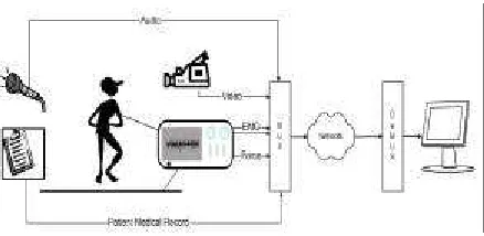
A Distributed Tele-Rehabilitation System is an application that helps remotely located clinicians work in a process of patient rehabilitation. With this system, clinicians are able to share medical information through the network to make diagnoses and discuss medical treatment for a patient. Figure 1 illustrates a Tele-Rehabilitation system.
Note: Discussion is expected before November, 1st 2003. The
proper discussion will be published in “Jurnal Teknik Elektro” Volume 4 Number 1 March 2004.
Figure 1 - Tele-Rehabilitation System
Zwaagstra [5]. The second one is the work of Lijun Peng [6].
The kind of information involved in the system will be identified first. They are as follows:
• Video information taken from the video camera. The video image gives information about patient movement during measurement process in the Tele-Rehabilitation system.
• Measurement signal taken from the measurement devices. There are several measurement devices involved in the system. The two most common are to measure Electromyograph (EMG) signal and to measure Force signal. For simplicity, the information that comes from the measurement devices will be called Medical Rehabilitation Signal Set (MRS Set).
• Patient Medical Record (PMR) given by the operator through the keyboard. They are data that describe the patient, clinician assessment and measurement condition.
• Audio annotation given by the operator through a microphone. It is available for clinician who prefers hearing audio information rather than reading textual information.
To implement the system mentioned above, MPEG-2 is chosen as the system infrastructure. Since MPEG-2 is chosen as the system infrastructure, the problem is how to do the implementation of the Distributed Tele-Rehabilitation system using MPEG-2 as the system infrastructure.
As a starting point, the following requirements are defined:
• The system needs time synchronization between video information and MRS Set information
• The system needs event synchronization between each transmission and PMR infor-mation
• The system should capable to handle mul-tiple MRS Set channel
• The system should accommodate different sampling rate and bits/sample
Medical Information
The following medical information was identified:
• Video information taken from the camera
• EMG signals and Force signals taken from the measurement devices (To simplify they will be called Medical Rehabilitation Signal Set (MRS Set))
• Audio information
• Patient Medical Record (PMR)
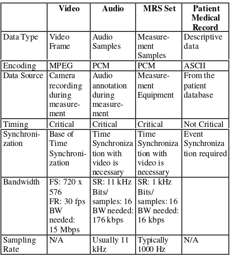
Table 1 below gives summary of Medical Infor-mation characteristic. This table is the result of analysis process for each kind of Medical Information [4], [7], [8], [9], [10], [11].
Table 1. Medical Information Characteristic
Video Audio MRS Set Patient Medical Record Data Type Video
Frame
Encoding MPEG PCM PCM ASCII
Data Source Camera recording
Timing Critical Critical Critical Not Critical
Synchroni-Bandwidth FS: 720 x 576
N/A Usually 11 kHz
Typically 1000 Hz
N/A
MPEG-2 Synchronization Mechanism
Time Synchronization is achieved through the use of Decoding Time Stamps (DTS), Presen-tation Time Stamps (PTS) and Clock References. Both Time Stamps are data fields indicating the appropriate time, according to a Systems Time Clock (STC) that a particular Presentation Unit (video pictures, audio frames, etc.) should be decoded by the decoder and presented to the output device. Clock References are data fields indicating the demultiplexer what the STC time should be when each clock reference is received.
If the decoding and presentation time are the same for a particular Presentation Unit then either no time stamp is sent or only the PTS is sent. If no time stamp is sent, then the presentation (and decoding) time is extrapolated based on the presentation time for the previous Presentation Unit and the known sampling rate for that source.
Both time stamps need to know what the STC time should be. This is achieved through the use of Clock References. In a Program Stream it is called System Clock Reference (SCR). In a Transport Stream it is called Program Clock Reference (PCR).
These clock references run at 27 MHz and are embedded in the stream every tenth of a second so the decoder can continually check for any drift between its clock and the one used by the encoder. If a discrepancy is detected, the decoder changes its clock to match the PCR time. The PCR is usually embedded in the video PES of a particular program. Since there is a PCR for each program in a multi program Transport Stream, each digitized program in the Transport Stream can be encoded at a different bit rate and by a different encoder.
Illustration for the synchronization mechanism is depicted in Figure 3.
Figure 3. MPEG-2 Synchronization Mechanism [2]
When MPEG-2 stream arrives, a demultiplexer separates the incoming stream into its component elementary stream and extracts Clock Reference (CR). The Presentation Units of the elementary stream then stored in buffers, where they wait until the proper time for decoding as specified by a Decoding Time Stamps (DTS) and the System Time Clock (STC).
Program Specific Information (PSI)
Tables
The PSI tables have the function almost similar to a file directory, i.e. to find the appropriate elementary stream from the complex Transport Stream. The PSI Tables in the Tele-Rehabilitation System are used to provide Event Synchronization mechanism.
Figure 4 illustrated the structure of PSI tables. In the figure there are more than k programs are listed in the PAT table. Each program consist a few streams (video, EMG and Force signal). The PIDs of the video, EMG and Force signal that belong in the same program stream are listed in the Program Map Table (PMT) packets. Private Network Data and Conditional Access Data are included in the NIT table and CAT table respectively.
Figure 4. PSI Structure
Private Data in MPEG-2
According to the MPEG-2 standard [1], there are some options for inclusion of private data in MPEG-2 system. Those options are described as follows:
1. Transport Stream Packet.
2. Transport Stream Adaptation.
The presence of any optional private data bytes in the adaptation field is signalled by the transport private data flag. The value of “1” means the presence of private data in the adaptation field. The number of the private data bytes in this way is inherently restricted by the semantic of the adaptation field_length field, where the value of the adaptation field length shall not exceed 183 bytes. This option also does not use PES and PSI tables’ functionalities.
3. PES packet
There are two possibilities for carrying private data within PES packets. The first one is within the PES packet header. The use of PES packet header to carry private data is only suitable for information with a low volume because of 16 bytes/packet limitation. It also does not support synchronization.
The second possibility is within the PES packet data byte field. This may be referred as private data. This category of private data can be split in two:
• private_stream_1 refers to private data within PES packets which follow the PES packet structure such that all fields up to and including, but not limited to, PES header data length are present.
• private_stream_2 refers to private data within PES packets where only the first three fields shall be present followed by the PES packet data bytes containing private data.
Using both options, the packet size length is limited up to 65535 bytes. Private_stream_1 has the advantage for synchronization, because it includes the header fields that are important for synchronization (PTS/DTS). On the other hand private_stream_2 does not include this header.
4. Descriptors
Program and program elementary descriptors are structures that can be used to extend the definitions of programs and program elements [1]. A range of private descriptors may be defined by the user. The format is simple , it only consists of tag, data length and private
data. These descriptors can be put in the PMT section or CAT section.
This option is not suitable for stream type data. It is only suitable for descriptive kind of data. It is also possible to relate the private data into another elementary stream. Another advantage is the size of private data can be extended using composite descriptor.
5. Private Section
The Private Section provides a further means to carry private data also in two forms. This type of elementary stream may be identified under stream type as private_data in PSI sections.
This option has the same advantage as using descriptor. The difference is that in this option, it is more difficult to relate private data with another elementary stream in the program.
In the case of Tele-Rehabilitation System, the following decision has been made:
• Medical Rehabilitation Signal Set is incorporated into MPEG-2 stream in the PES Packet Data Byte Field with Elementary Stream stream_id 0xBD. It is because this is the only option that enables Time Synchronization mechanism (i.e. PTS,DTS)
• Patient Medical Records are placed as descriptors in the Program Map Table for the reason that it is easier to relate PMR with other stream compare to using Private Section.
PDU Design
The PDU are designed to accommodate the following requirements:
• capability to handle multiple MRS Set channel
• capability to accommodate different sam-pling rate and bits/sample for each channel of MRS Set information
MRS Set PDU
Figure 5. MRS Set Elementary Stream Structure
Scan Pattern PDU contains three fields of information:
• Frame ID; it is used to identify that a certain frame contains a scan pattern. For this purpose a specific frame ID is allocated. The allocated frame ID is 0x5F5350 (hexadecimal code for _SP)
• Number of Channel; it is used to identify how many channels of MRS Set are involved. It is also useful to let the decoder know how many bytes of pattern information have to be read. To specify this information 1 byte should be enough.
• Scan Pattern; it is used to inform the decoder the scan pattern for MRS Set Samples PDU. The length of this part depends on the number of channels. One byte is allocated for each data in the scan pattern.
MRS Set Samples PDU contains two fields of information:
• Frame ID; it is used to identify that a certain frame contains a sequence of MRS Set samples. For this purpose a specific frame ID is allocated. The allocated frame ID is 0x4D5352 (hexadecimal code for MRS).
• Channel Samples; this field is used to represent each sample from MRS Set. Each sample is represented by 4 bytes data. It should be enough to accommodate the need of different number of bits per sample up to 32 bits.
Each field in the MRS Set PDUs is represented as unsigned integer a value with the most significant bit comes first (uimsbf). Figure 6 shows the frame syntax of Scan Pattern PDU. Figure 7 shows the frame syntax of MRS Set Samples PDU.
Syntax No of Bits Mnemonic
Scan_Pattern() {
Frame_ID 24 uimsbf
No_of_Channel (=N) 8 uimsbf
For (i=0;i<N;i++) { Scan_Pattern (=P(i))
8 uimsbf
} }
Figure 6. Frame Syntax of Scan Pattern PDU
Syntax No of Bits Mnemonic
MRS_Set_Samples() {
Frame_ID 24 uimsbf
For (i=0;i<N;i++) { For (j=0;j<P(i);j++) {
MRS Sample 32 uimsbf
} }
}
Figure 7. Frame Syntax of MRS Set Samples PDU
PMR PDU
PMR PDU follows the Descriptors structure defined in MPEG-2 standard. Further on, in this section PMR PDU will be called PMR descriptors. All descriptors have a format that begins with an 8 bit tag value. The tag value is followed by 8 bit descriptor length and data fields
As mentioned in the introduction, PMR can be categorized into 3 categories:
o Patient Identification data o Clinical Assessment data o EMG and Force reporting data
To carry these three categories of PMR we need three descriptors. For the descriptor tags, the possible tags are between 64 and 255 (Please refer to Table 2.39 in MPEG-2 Standard [1]). For our purpose, we will use tags value 64 to 66. List of descriptor and descriptor tag for PMR is depicted in Table 2 below.
Table 2. Private Descriptor for PMR
PMR Information Category Descriptor Tag
Patient Identification data 64
Clinical Assessment data 65
EMG and Force reporting data 66
information structure for PMR. To solve this problem, there will be 2 fields in each descriptor data. The first field stores information structure of PMR. The second field contains the real information based on the information structure in the first field.
For example, Patient Identification data has the following information structure:
• Patient ID
• Patient Name
• Address
• Phone Number
• Birthday
This structure will be stored in the first data field of descriptor. The real information about patient ID, name, etc will be stored in the second data field. All the information is stored in the free form text format represented by bit-string. To distinguish a specific information among each other in each field, a fixed separator value 0x7C (”|”) will be used.
The semantic description for PMR descriptor is depicted in Figure 8. All the three descriptors of PMR follow the same semantic description. The only difference between those three descriptors is the length of data field. For now, length of data field for each descriptor will be left to the implementor because there is no real data to support the decision of the length of data field.
Syntax No of Bits Mnemonic
PMR_Descriptor() {
descriptor_tag 8 uimsbf
descriptor_length 8 Uismbf
information_structure … bslbf
information_value … bslbf
}
Figure 8. Semantic Description for PMR Descriptor
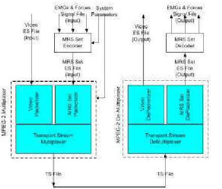
Implementation
The implementation consists of the following programs (application parts):
• MRS Set Encoder; this is where EMG signals and Force signals are multiplexed together to create an MRS Set Elementary Stream. For the purpose of demonstration, the inputs of the MRS Set encoder do not come from the real measurements. The inputs of MRS Set encoder in the demonstrator are files that contain artificially
generated sample values. The output of the MRS Set encoder is a file contains an MRS Set Elementary Stream.
Figure 9. Implementation Architecture
• MPEG-2 Multiplexer contains Packetizer and Transport Stream Multiplexer; this is where MRS Set Elementary Stream and Video Elementary Stream are packetized and multiplexed, and descriptors for PMR are incorporated.
Audio Elementary Stream is not included in order to make the demonstrator less complicated. The way to multiplex Audio Elementary Stream along with the Video Elementary Stream is basically the same.
PMR is incorporated through system parameter of MPEG-2 Multiplexer. At this moment we do not build special encoder for PMR. They are directly fed to the PSI Producer (i.e. PM Section) in the Transport Stream Multiplexer.
The input of this part comes from MRS Set Elementary Stream file generated from MRS Set encoder. The output of this part is a file containing a Transport Stream.
outputs are Video Elementary Stream file and MRS Set Elementary Stream file.
• MRS Set Decoder; this is where the decoding process to display the MRS Set Elementary Stream happens. The input of MRS Set decoder is MRS Set Elementary Stream file that comes from the MPEG-2 De-Multiplexer. The outputs are EMG and Forces Signal files.
To perform the implementation, some program library has been used. They are MSYS Toolkit [14] and bbTools [15].
Implementation Result
For testing purpose, the following files are used to present result of the implementation
o emg1.txt and emg2.txt; represents EMG signal with sampling rate 500 samples/ second and number of bits/sample is 16. o Force.txt; represents Force signal with
sampling rate 100 samples/second and number of bits/sample is 16
The plot of data before and after multiplexing process is shown in Figure 10. It shows that MRS Set information successfully goes through the multiplexer and can be decoded perfectly in the other end.
Figure 10. MRS Set Plot
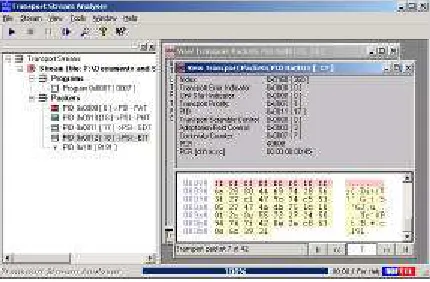
The output of Transport Stream Multiplexer also inspected using Transport Stream Analyzer from SoftTel [16]. Figure 11 depicted the result.
Figure 12. Transport Stream File Inspection
From the figure above, the followings thing can be seen:
o There is a single program in the Transport Stream file (Program 0x7)
o In the program there are:
§ Program Association Table (PID 0) § Program Map Table (PID 16) § Video Stream (PID 18)
§ Private Stream (i.e. MRS Set Stream, PID 17)
It also shows that the multiplexer works well.
Conclusion
In conclusion, the decision to use MPEG-2 as infrastructure for Distributed Tele-Rehabilitation System is a correct choice. Some important facts that support this statement are:
• Medical Rehabilitation Signal Set can be incorporated into MPEG-2 stream in the PES Packet Data Byte Field with Elementary Stream stream_id 0xBD.
• Patient Medical Records can be placed as descriptors in the Program Map Table.
• Time Synchronization can be achieved through the use of DTS, PTS and Clock Reference in MPEG-2 stream
• Event Synchronization can be achieved through the association using PID in the PSI tables
• An implementation has been carried out and it works well
In the end there are more improvements that can be performed on the design and implementation of the system. Among others, they are as follow:
• Refine the specification for PMR PDU. For this purpose, a more detailed investigation about the information structure of PMR is still needed.
emg1
emg2
force1
emg1
emg2
force1
• Design a user friendly interface for the sending and receiving user of the Distributed Tele-Rehabilitation System in the real application. For this purpose, a more collaborative work with operators and clinicians in the rehabilitation center are needed.
References
[1] ISO/IEC, ISO/IEC 13112-1, “Generic Coding of Moving Pictures and Associated Audio: Systems”, April 1999.
[2] Haskell, B.G. and Puri, A.P. and Netravali, Arun N., Digital Video: An Introduction to MPEG-2, Chapman & Hall , New York, 1997.
[3] Kleissen RFM, Buurke JH, Harlaar J, Zilvold G., Electromyography in the Biomechanical Analysis of Human Move-ment and Its Clinical Application, Gait and Posture 8 (1998) 143-158.
[4] DelSys Incorporated, ”Surface Electro-myography: Detection and Recording”. URL: http://www.delsys.com/library/ papers/SEMGintro.pdf
[5] Zwaagstra, Sjoerd L., Coding of Surface-EMG Signals in MPEG-2, University of Twente, July 2000.
[6] Lijun Peng, (De) Multiplexing Medical Rehabilitation Data With MPEG-2 in Tele-Rehabilitation System.
[7] Winter, David A., Biomechanics and Motor Control of Human Movement, 2nd Edition, A Wiley – Interscience Publica-tion, 1990
[8] DelSys Incorporated, "Fundamental Con-cepts of Data Acquisition”, URL:
http://www.delsys.com/library/papers/fund 1_4.pdf
[9] DelSys Incorporated, “Considerations for Analog to Digital Converter”, URL:
http://www.delsys.com/library/papers/fund 6.pdf
[10] Luca, Carlo De, “The Use of Surface Electromyography in Biomechanics”, DelSys Incorporated, 1997, URL:
http://www.delsys.com/library/papers/bio mechanics.pdf
[11] Private Communication with Kleissen, R. F. M.
[12] Merletti, R., Standards for Reporting EMG Data,URL: http://isek.bu.edu/publications/ standards/emg_standards.html
[13] Tektronix, Inc. A Guide To MPEG Fundamentals and Protocol Analysis (Including DVB and ATSC), 1997
[14] MSYS Toolkit, URL: ftp://tek.com (it is not available anymore)
[15] bbTools, URL: http://members.home.net/ beyeler/bbmpeg.html
[16] SoftTel Transport Stream Analyzer, URL:
http://www.softel.co.uk
![Figure 3. MPEG-2 Synchronization Mechanism [2]](https://thumb-ap.123doks.com/thumbv2/123dok/3654780.1466370/3.596.84.297.480.626/figure-mpeg-synchronization-mechanism.webp)