O. K ¨ung1,2, C. Strecha1,2, A. Beyeler3, J-C. Zufferey3,4, D. Floreano4, P. Fua1,2and F. Gervaix5,6
KEY WORDS:Ultra-light UAV, mini-drone, photogrammetry, orthomosaic, DEM, automated georeferencing, aerial triangulation
ABSTRACT:
This paper presents an affordable, fully automated and accurate mapping solutions based on ultra-light UAV imagery. Several datasets are analysed and their accuracy is estimated. We show that the accuracy highly depends on the ground resolution (flying height) of the input imagery. When chosen appropriately this mapping solution can compete with traditional mapping solutions that capture fewer high-resolution images from airplanes and that rely on highly accurate orientation and positioning sensors on board. Due to the careful integration with recent computer vision techniques, the post processing is robust and fully automatic and can deal with inaccurate position and orientation information which are typically problematic with traditional techniques.
1 INTRODUCTION
Fully autonomous, ultra-light Unmanned Aerial Vehicles (UAV) have recently become commercially available at very reasonable cost for civil applications. The advantages linked to their small mass (typically around 500 grams) are that they do not represent a real threat for third parties in case of malfunctioning. In ad-dition, they are very easy and quick to deploy and retrieve. The drawback of these autonomous platforms certainly lies in the rel-atively low accuracy of their orientation estimates. In this paper, we show however that such ultra-light UAV’s can take reasonably good images with large amount of overlap while covering areas in the order of a few square kilometers per flight.
Since their miniature on-board autopilots cannot deliver extremely precise positioning and orientation of the recorded images, post-processing is key in the generation of geo-referenced orthomo-saics and digital elevation models (DEMs). In this paper we evaluate an automatic image processing pipeline with respect to its accuracy on various datasets. Our study shows that ultra-light UAV imagery provides a convenient and affordable solution for measuring geographic information with a similar accuracy as larger airborne systems equipped with high-end imaging sensors, IMU and differential GPS devices.
In the frame of this paper, we present results from a flight cam-paign carried out with the swinglet CAM, a 500-gram autonomous flying wing initially developed at EPFL-LIS and now produced by senseFly. The swinglet CAM records 12MP images and can cover area up to 10 square km. These images can easily be geo-tagged after flight using the senseFly PostFlight Suite that pro-cesses the flight trajectory to find where the images have been taken. The images and their geotags form the input to the pro-cessing developed at EPFL-CVLab. In this paper, we compare two variants:
• The first one consists of an aerial triangulation algorithm
based on binary local keypoints. Its output is a geo-referenced orthomosaic together with a DEM of the surveyed area. In
its basic form, no ground control point (GCP) is used and the geo-localization process only depends on the GPS mea-surements (geotags) provided by the UAV. This is a fully automated, “one click” solution.
• Optionally, GCPs can be spotted in the original images and
automatically taken into account by the algorithm to im-prove the geolocalisation accuracy. The procedure allows removal of the geo-location bias which is due to the geotag inaccuracy. Except for the GCP measurements on the field and determination on the original images, no other manual intervention is needed to produce the results.
Depending on the application, the burden of measuring GCP can be traded against a lower resulting accuracy. This suites vari-ous needs in terms of accuracy, time to result and cost. Growers or people engaged in field mission planning for instance may be interested obtain a quick survey in the form of a georeferenced orthomosaic produced fully automatically within minutes. We show that the accuracy without GCP lies in the range of 2m for low altitude imagery. With just a little bit more of human inter-vention, i.e. the designation of a couple of GCPs in the images, an accuracy of 0.05-0.2m can be achieved. This accuracy largely depends on the ground resolution of the original images as will be shown later on.
Figure 1: The swinglet CAM mini-UAV weighs 500 grams and has a wingspan of 80 cm. It is equipped with a pusher electric engine, a rechargeable and swappable lithium-polymer battery, two servo motors to control its elevons, a 12 MP pocket camera, an autopilot including rate gyroscopes, accelerometers, and GPS, a Pitot tube to measure airspeed and barometric altitude. Image courtesy of senseFly LLC.
analysis of local areas, as for instance the monitoring of recon-struction sites, becomes on one hand affordable because of the reduced cost of the hardware. Expensive helicopters or airplanes are replaced by ultra-light UAV’s. The automated processing on the other hand reduces the labor cost substantially and makes such projects, which would normally require a lot of manual in-tervention using traditional photogrammetry techniques, feasible for the first time.
This paper is organized as follows. The next section provides an overview of the ultra-light UAV image capturing device used in this paper. Section 3 describes the whole processing chain that we applied in this test. It contains the evaluation of the accuracy of the two methods, which consists of a full bundle block adjust-ment over image correspondences with and without using ground control points. Several datasets are evaluated and the results are summarised in Section 4.
2 AERIAL IMAGE CAPTURE SYSTEM
The swinglet CAM (Figure 1) is an electrically-powered 500-gram flying wing1 including a full-featured autopilot and an in-tegrated 12 MP still camera. Its low weight combined with its flexible-foam airframe makes it particularly safe for third parties as it has approximately the same impact energy as a medium-sized bird. The swinglet CAM has a nominal airspeed of 10m/s, is capable of withstanding a moderate breeze of up to 7m/s and features a flight endurance of 30 minutes. It is launched by hand, which makes it particularly quick to deploy when compared to systems requiring a catapult of other launching facilities. It lands by gliding down in tight spirals, which makes the whole proce-dure particularly easy to program and monitor.
The built-in autopilot relies on a set of rate gyroscopes, accelerom-eters, pressure sensors and a GPS to compute and control the state of the UAV and to follow a 3D path defined by waypoints. The autopilot also manages the camera to enable good coordination.
1
Initially developed at EPFL-LIS, this platform has been used for au-tomated flight in cluttered environments (Zufferey et al., 2010) as well as collective behaviour experiments (Hauert et al., 2011)
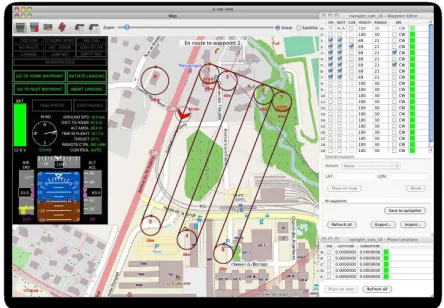
Figure 2: The e-mo-tion software is used to program and monitor the swinglet CAM through a wireless communication link. Image courtesy of senseFly LLC.
In particular, the picture taking process encompasses a prepro-grammed set of actions in order to lower the risk of image blur due to vibrations or turbulences. To take a picture, the autopilot will first completely cut off the engine for a few seconds while stabilizing the plane in a level attitude before triggering the cam-era. Once this procedure is completed the normal navigation will resume and the small resulting altitude loss or path offset will be swiftly corrected by the normal flight controller.
The swinglet CAM comes with a software called e-mo-tion (Fig-ure2), which connects to the autopilot by means of a 2.4 GHz ra-dio modem within a range of up to 2km. This application can be installed on almost any computer running Windows or MacOS. It features a map window on which waypoints can easily be dragged and dropped to build a flight plan or edit it. This process can take place either before or during flight. Since all waypoint changes are directly sent and stored onboard the autopilot, a temporary loss of communication will not prevent the swinglet from contin-uing its mission. In addition to programming the flight path, e-mo-tion serves many other purposes such as monitoring the status of the mini-UAV, logging flight data for further analysis and pro-cessing after the flight, programming where and how often aerial images should be taken, displaying estimated image footprints on the map in real-time, etc.
For photogrammetric flights, the swinglet can be programmed to take pictures in a systematic way while flying along its flight plan between every pair of waypoints. E-mo-tion also includes a tool to automatically create flight plans to systematically cover some designated area. This tool will position and configure a set of waypoints to achieve the desired ground resolution (typically be-tween 3 and 30cm corresponding to 80 to 800m flight altitude above ground) as well as longitudinal and lateral image overlap.
An additional piece of software named PostFlight Suite allows you to process the data acquired in flight in order to replay the 3D flight trajectory in Google EarthTM(Figure3) or to geotag the ac-quired images on the basis of the recorded flight log. These geo-tags present a typical accuracy of 5-10m in position and of3−5◦
Figure 3: Example of a real 3D flight trajectory as produced by the PostFlight Suite software and displayed in Google EarthTMfor visualization.
2011a) onto a web-based server powered by Pix4D (Pix4D, 2011) to automatically produce orthomosaics and digital elevation mod-els (DEM).
3 AUTOMATED DATA PROCESSING
The web-based service that can automatically process up to 1000 images, is fully automated and requires no manual interaction. Geo-referenced orthomosaic and DEM can be obtained in prin-ciple without the need for ground control points. However, as shown in the various examples provided in this section, more ac-curate results can be obtained by using GCP. The software per-forms the following steps:
• The software searches for matching points by analyzing all
uploaded images. Most well known in computer vision is the SIFT (Lowe, 2004) feature matching. Studies on the per-formance of such feature descriptors are given in (Mikolajczyk and Schmid, 2002). We use here binary descriptors similar to (Strecha et al., 2011), which are very powerful to match keypoints fast and accurate.
• Those matching points as well as approximate values of the
image position & orientation provided by the UAV autopilot are used in a bundle block adjustment (Triggs et al., 2000,
Hartley and Zisserman, 2000) to reconstruct the exact po-sition and orientation of the camera for every acquired im-age (Tang and Heipke, 1996).
• Based on this reconstruction the matching points are verified
and their 3D coordinates calculated. The geo-reference sys-tem is WGS84, based on GPS measurements from the UAV autopilot during the flight.
• Those 3D points are interpolated to form a triangulated
ir-regular network in order to obtain a DEM. At this stage, at dense 3D model (Scharstein and Szeliski, 2002,Strecha et al., 2003,Hirschmller, 2008,Strecha et al., 2008b) can in-crease the spatial resolution of the triangle structure.
• This DEM is used to project every image pixel and to
cal-culate the georeferenced orthomosaic (also called true or-thophoto) (Strecha et al., 2008a).
0
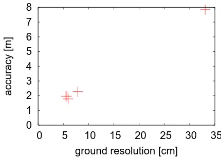
Figure 4: Dependency of the accuracy from the ground resolution (Ground sampling distance) of the original images for various datasetswithout using GCPsfor the reconstruction (“geotags only“).
In order to assess the quality and accuracy of this automated pro-cess, we consider here several projects that differ with respect to the coverage area, ground resolution, overlap between original images and the number of images. For all datasets we measured GCPs, which we then used to evaluate the precision of the auto-mated reconstruction. Thereby we evaluated two different meth-ods. One is purely based on the geotags of each original image as provided by the UAV autopilot and one which in addition also takes manually designated GCPs into account. For both we mea-sure the accuracy of the result as the mean distance between the triangulated GCPsxj, as optimized by Eq.1and the GCP po-sitionsXjas obtained by a high-precision GPS receiver on the ground. Letpijbe the position of GCPjin imagei. The collec-tion of allpijfor a given GCPjgive rise to a 3D pointxjthat
wherePi(xj)performs the projection of xj into imageiand
Σijdescribes the accuracy of thepijthGCP when measured in imagei. The accuracy of the reconstruction is then measured by the varianceσ:
Note thatXjandxjare 3-vectors such that Eq.2measures the variance of a three dimensional distance.
The accuracy in Eq.2can be computed by taking the GCPs into account when performing the reconstruction, which is referred to as “including GCPs” in the results section below and can be computed without using them (“geotags only”).
number ground flying area number
images resolution height GCPs
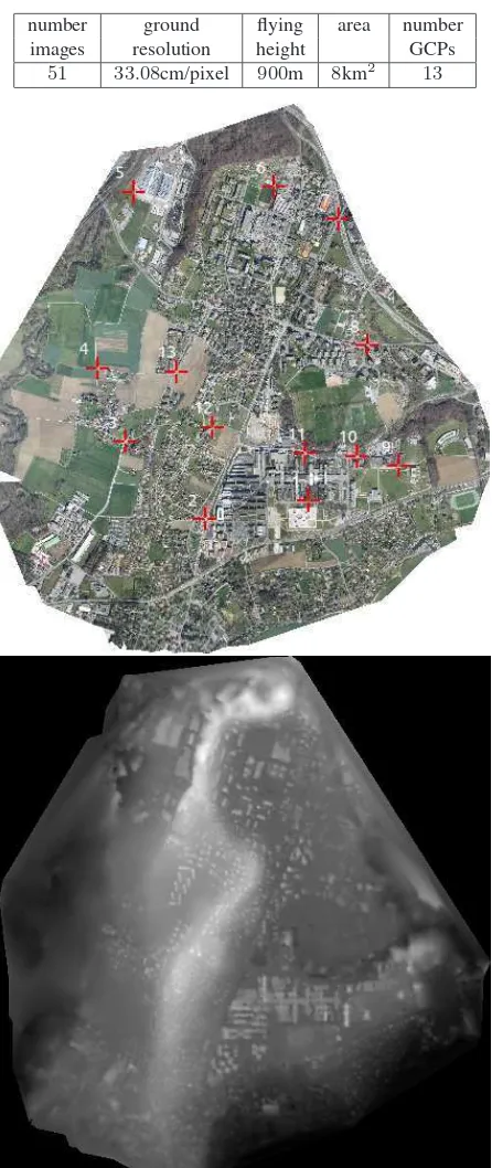
51 33.08cm/pixel 900m 8km2 13
Table 1: Ecublens Dataset: The table contains the specification of this dataset. We show furthermore the orthomosaic with the GCPs in red and the DEM.
0
0.2
0.4
0.6
0.8
1
1.2
0
5
10 15 20 25 30 35
accuracy [m]
ground resolution [cm]
Figure 5: Dependency of the accuracy from the ground resolu-tion (Ground sampling distance) of the original images for var-ious datasetsby using GCPsfor the reconstruction (“including GCPs”).
the datasets. These and more datasets are available for closer vi-sualization on (SenseFly, 2011b).
The accuracy results for each of the three datasets are shown in Tables2, 4and 6. We report the accuracyσfrom Eq.2for the two reconstruction methods ”including GCPs“ and ”geotags only“ as well as the accuraciesσx, σy, σzin each coordinate di-rection.
In Figures4and5, we plot the accuracyσas a function of the image ground resolution for the three datasets above and for two others for which we cannot show detailed results due to space limitation. All experiments confirm the expected dependency of the accuracy on the ground resolution of the original images. We can conclude that the accuracy lies between 0.05-0.2m when in-cluding GCPs and 2-8m with the no-manual-intervention variant. However, this accuracy can not be achieved for all parts of the or-thomosaic. Some areas might not be very well textured or could contain large discontinuities in depth (for instance near building boundaries or thin tree structures). For those areas the accuracy will be slightly worse. To evaluate this, more experiments with LiDAR as ground truth are necessary (Strecha et al., 2008b).
The accuracy figures presented here could be further improved by following a traditional photogrammetric work-flow (R-Pod, 2011), that includes manual intervention to define more stable control points. This strategy might especially be necessary when the image quality and overlap is insufficient for an automated work-flow.
4 SUMMARY
σ 7.84 1.25 σx 2.45 0.37 σy 4.40 0.38 σz 5.42 1.07
Table 2: Ecublens Dataset: The accuracy of the geolocation (top) and the original image geotags (bottom) are given. At approx-imately 40cm ground resolution and with GCPs acquired by google the mean localisation error is1.25m by using and about
8m without using GCPs.
overcome this problem. We believe that this approach will en-able a range of decision-makers to create their own maps on the spot and on demand. This can be very useful in many fields such as agriculture, land management, forestry, humanitarian aid, mis-sion planning, mining, architecture, archeology, urban planning, geology, wild life monitoring, forestry and many others.
We can conclude that the accuracy lies between 0.02-0.2m de-pending on the ground resolution of the original images. How-ever, this accuracy can not be achieved for all parts of the or-thomosaic. Some areas might not be very well textured or could contain large discontinuities in depth (for instance near building boundaries or thin tree structures). For those areas the accuracy will be worse.
To evaluate this, more experiments with LiDAR as ground truth are necessary (Strecha et al., 2008b).
ACKNOWLEDGMENTS
REFERENCES
Eisenbeiss, H. and W.Stempfhuber, 2009. Genauigkeitsanalyse der 3D-Trajektorie von Mini-UAVs. In: Zukunft mit Tradi-tion: 29. Wissenschaftlich-Technische Jahrestagung der DGPF, pp. 407–417.1
Hartley, R. and Zisserman, A., 2000. Multiple View Geometry in Computer Vision.3
Hauert, S., Leven, S., Varga, M., Ruini, F., Cangelosi, A., Zuf-ferey, J. and Floreano, D., 2011. Reynolds flocking in reality with fixed-wing robots: communication range vs. maximum turning rate. In: Proceedings of the IEEE/RSJ International Conference on Intelligent Robots and Systems.2
Hirschmller, H., 2008. Stereo processing by semiglobal matching and mutual information. IEEE Trans. Pattern Anal. Mach. Intell. pp. 328–341.3
Lowe, D., 2004. Distinctive Image Features from Scale-Invariant Keypoints. IJCV 20(2), pp. 91–110.3
Mikolajczyk, K. and Schmid, C., 2002. An Affine Invariant In-terest Point Detector. In: ECCV, pp. 128–142.3
Pix4D, 2011. Hands free solutions for mapping and 3D modeling
"www.pix4d.com".3
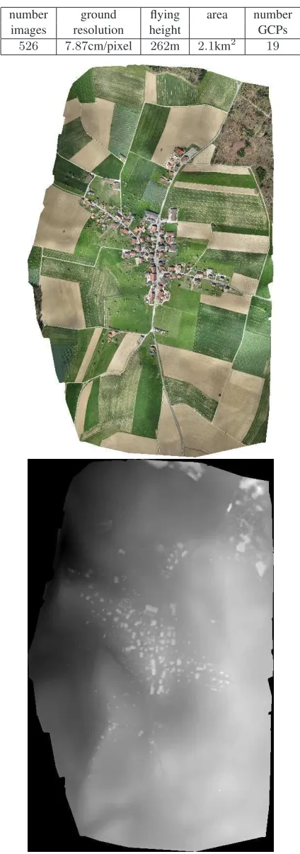
526 7.87cm/pixel 262m 2.1km 19
GCPs error [m] geotags only including GCPs σ 2.28 0.19
σx 0.50 0.130
σy 1.76 0.117
σz 1.29 0.045
Table 4: Penthereaz Dataset: The accuracy of the geolocation (GCPs) and the original image geotags are given. At approx-imately6 cm ground resolution and with GCPs acquired by a high accuracy GPS receiver the mean localisation error is20cm by using and about2.3m without using GCPs.
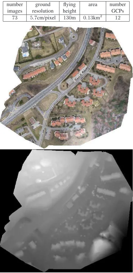
number ground flying area number
images resolution height GCPs
73 5.7cm/pixel 130m 0.13km2 12
Table 5: Epalinges Dataset: The table contains the specification of this dataset. We show furthermore the orthomosaic and the DEM.
GCPs error [m] geotags only including GCPs
σ 1.97 0.056
σx 0.58 0.028
σy 0.65 0.038
σz 1.76 0.017
Table 6: Epalinges Dataset: The accuracy of the geolocation (GCPs) and the original image geotags is given. At approxi-mately6cm ground resolution and with GCPs acquired by a high accuracy GPS receiver the mean localisation error is6cm by us-ing and about2m without using GCPs.
R-Pod, 2011. Photogrammetry On Demand"www.r-pod.ch". 4
Scharstein, D. and Szeliski, R., 2002. A Taxonomy and Evalu-ation of Dense Two-Frame Stereo Correspondence Algorithms. IJCV 47(1/2/3), pp. 7–42.3
SenseFly, 2011a."www.sensefly.com".3
SenseFly, 2011b. Example datasets for mapping
"www.sensefly.com/applications/mapping".4
Strecha, C., Bronstein, A., Bronstein, M. and Fua, P., 2011. LDA-Hash: improved matching with smaller descriptors. IEEE Trans-actions on Pattern Analysis and Machine Intelligence.3
Strecha, C., Gool, L. V. and Fua, P., 2008a. A generative model for true orthorectification. Proceedings of theInternational Soci-ety for Photogrammetry and Remote Sensing (ISPRS).3
Strecha, C., Tuytelaars, T. and Gool, L. V., 2003. Dense matching of multiple wide-baseline views. Proceedings of the International Conference on Computer Vision (ICCV) pp. 1194–1201.3
Strecha, C., von Hansen, W., Gool, L. V., Fua, P. and Thoen-nessen, U., 2008b. On benchmarking camera calibration and multi-view stereo for high resolution imagery. Proceedings of the IEEE Conference on Computer Vision and Pattern Recogni-tion pp. 1–8.3,4,5
Tang, L. and Heipke, C., 1996. Automatic relative orientation of aerial images. Photogrammetry and Remote Sensing 62(1), pp. 47–55.3
Triggs, B., McLauchlan, P., Hartley, R. and Fitzgibbon, A., 2000. Bundle Adjustment – a Modern Synthesis. In: Vision Algo-rithms: Theory and Practice, pp. 298–372.3