DETECTION AND PURGING OF SPECULAR REFLECTIVE AND TRANSPARENT
OBJECT INFLUENCES IN 3D RANGE MEASUREMENTS
R. Kocha,∗, S. Maya, A. N¨uchterb a
Technische Hochschule N¨urnberg Georg Simon Ohm, Kesslerplatz 12, 90489 N¨urnberg, Germany - www.th-nuernberg.de, (rainer.koch, stefan.may)@th-nuernberg.de
b
Informatics VII – Robotics and Telematics, Julius-Maximilians University W¨urzburg, Am Hubland, 97074 W¨urzburg, Germany - www.uni-wuerzburg.de, [email protected]
Commission II
KEY WORDS:Robotics, 3D laser scanning, Measurement, Error, Detection, Segmentation, Correction, Algorithms
ABSTRACT:
3D laser scanners are favoured sensors for mapping in mobile service robotics at indoor and outdoor applications, since they deliver precise measurements at a wide scanning range. The resulting maps are detailed since they have a high resolution. Based on these maps robots navigate through rough terrain, fulfil advanced manipulation, and inspection tasks. In case of specular reflective and transparent objects, e.g., mirrors, windows, shiny metals, the laser measurements get corrupted. Based on the type of object and the incident angle of the incoming laser beam there are three results possible: a measurement point on the object plane, a measurement behind the object plane, and a measurement of a reflected object. It is important to detect such situations to be able to handle these corrupted points. This paper describes why it is difficult to distinguish between specular reflective and transparent surfaces. It presents a 3D-Reflection-Pre-Filter Approach to identify specular reflective and transparent objects in point clouds of a multi-echo laser scanner. Furthermore, it filters point clouds from influences of such objects and extract the object properties for further investigations. Based on an Iterative-Closest-Point-algorithm reflective objects are identified. Object surfaces and points behind surfaces are masked according to their location. Finally, the processed point cloud is forwarded to a mapping module. Furthermore, the object surface corners and the type of the surface is broadcasted. Four experiments demonstrate the usability of the 3D-Reflection-Pre-Filter. The first experiment was made in a empty room containing a mirror, the second experiment was made in a stairway containing a glass door, the third experiment was made in a empty room containing two mirrors, the fourth experiment was made in an office room containing a mirror. This paper demonstrate that for single scans the detection of specular reflective and transparent objects in 3D is possible. It is more reliable in 3D as in 2D. Nevertheless, collect the data of multiple scans and post-filter them as soon as the object was bypassed should pursued. This is why future work concentrates on implementing a post-filter module. Besides, it is the aim to improve the discrimination between specular reflective and transparent objects.
1. INTRODUCTION
3D laser scanners are common used sensors in service robotics, e.g., in industrial, medical, and rescue application. It is a favoured sensor, since the sensor is suitable for indoor and outdoor appli-cations, delivers precise measurements, and has a wide scanning range. This allows robots to navigate trough rough terrain, ful-fil advanced manipulation, and inspection tasks. Unfortunately laser scanners are expensive and have a drawback when scanning specular reflective or transparent surfaces, e.g., glass, mirrors, or shiny metal.
In case of a specular reflective object, e.g., a mirror, the laser beams get reflected and rerouted to an object located in front of the mirror. Therefore, the return measurements result from an mirrored object. Hence, the measured location of the object is wrong.
In case of a transparent object, e.g., a window, the measurements of the laser beams result partly from the transparent surface and partly from the objects behind the surface, depending on the inci-dent angle of the laser beam. It is understood that such erroneous measurements lead to difficulties in navigation. If the object sur-face is not seen at all or only occasional seen the robot might manoeuvre into the object and crashes.
∗Corresponding author: Rainer Koch ([email protected]), Technische Hochschule N¨urnberg Georg Simon Ohm, Kesslerplatz 12, 90489 N¨urnberg, Germany, www.th-nuernberg.de
To prevent such situations customizing most environments is nec-essary to reduce interferences from objects with specular reflec-tive and transparent surfaces like glass, mirrors, or shiny metal. Customizing is unwanted since it takes a lot of time. Besides, it is not always possible, e.g., when operating in rescue scenarios. That is why many approaches employ a second sensor principle like ultrasonic arrays, to respect these situations.
Contrary, this paper presents an approach, further called 3D-Ref-lection-Pre-Filter, that relies only on a multi-echo laser scanner. It is online applicable in order to pre-filter laser point clouds to reduce above mentioned effects. Section 2.1 outlines related work. Following, Section 2.3 describes the 3D-Reflection-Pre-Filter Approach. In Section 2.4 four experiments demonstrate the applicability to environments with reflective and transparent planar objects. Finally, Section 3. summarizes the results and gives an outlook for future work.
2. MAIN BODY
2.1 Related Work
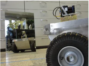
Figure 1: Robot equipped with the 3D-Hokuyo multi-echo laser scanner facing an unframed mirror.
2D and 3D mapping with mobile robots and influences of specu-lar reflective and transparent objects at laser scanners.
Yang et al. (Yang and Wang, 2008) presented a 2D mapping ap-proach which fuses a laser scanner with an ultrasonic sensor to avoid the need to cover surfaces. With the assumption that reflec-tive objects are flat and framed, the data from the two sensors are compared w.r.t. consistency. Mirrors are detected and tracked on-line, while resulting errors are recalculated only offline. In further research Yang et al. (Yang and Wang, 2011) extended their algo-rithm for advanced mirror detection and identification of mirror images. The extended approach assumes each gap in the wall to be a specular reflective object. Therefore, no ultrasonic sensor is required anymore. Once such a mirror candidate is detected, the space behind the gap is analysed for a mirrored image, i.e., the search for similarity between both sides of the opening. Objects with symmetry w.r.t. a line might be identified wrongly.
Another online applicable 2D approach was implemented by Forster et al. (Foster et al., 2013). They show that at specific angles re-flections can be identified based on the returning intensity of the laser. The algorithm tracks a subset of these angles – on occur-rence mirrors are assigned in dependency of the laser beam’s in-tensity. The identification fails, if a diffuse reflective object is placed directly behind a transparent object. Besides, there is no effort on discrimination of specular reflective and transparent ob-jects done.
Koch et al. (Koch et al., 2016) presented a 2D Mirror Detector Approach comprising a pre-filter module, a post-filter module, and two mapping modules. The approach uses an Hokuyo UTM-30LX-EW multi-echo laser scanner. The pre-filter module ap-plies on the fly and reduces identified points behind a specular reflective or transparent object in current scans. Therefore, the distance values of Echo 1 and Echo 2 are compared. Discon-tinuities indicate specular reflective or transparent object influ-ences. The smaller distance value of both echoes results from the surface, while the larger distance value results from the object behind or the mirrored object. The algorithm masks all points based on their belonging - regular scan point, point on the sur-face, or point behind the surface. Following, the first mapping module builds a preliminary map based on the pre-filtered scans. Points behind the surface are excluded. The post-filter creates an history of these pre-filtered scans. It evaluates all scans, triggered as soon as the reflective or transparent surface has been passed. Similar to the pre-filter each point of the scan gets evaluated, if it is a regular scan point, a point on the surface, or a point behind the surface. Finally, the second mapping module builds a refined map based on the evaluated scans.
In further research Koch et al. (Koch et al., 2017) extended their algorithm. The Reflection Classifier Approach is reduced to one
mapping stage. The applied TSD mapping is extended to up-date maps as soon as the post-filter sends refined scans. Further, Koch et al. included a function to distinguish between specular reflective and transparent objects based on their intensity values. In two experiments the properties of different materials (spec-ular reflective, transparent, and diffuse reflective materials) are investigated. A third experiment show the results of the applied Reflection Classifier Approach.
K¨ashammer et al. (K¨ashammer and N¨uchter, 2015) presented an approach which recognises framed mirrors with a predefined size in 3D point clouds. The algorithm generates panorama range im-ages and searches for jumping edges. In case of a positive search, the contour of the mirror frame is extracted. Finally, objects are verified by considering their size and shape. This only applies to framed squared mirrors with a known size. Glass or other objects are not considered. Furthermore, points behind the identified mir-ror plane are erased. There is no effort done to back-project them to their original location and use them to improve mapping.
We present a 3D-mirror-pre-filter approach applicable to multi-echo laser scanners in order to identify and filter specular reflec-tive and transparent objects. In contrast to above mentioned ap-proaches this online running approach identifies and filters spec-ular reflective and transparent objects. It recognises frameless and free-standing objects in 3D point clouds regardless their size. Furthermore, it back-projects points which are located behind a mirror plane to improve mapping. Therefore, it is assumed that objects are planar and square shaped.
2.2 Hardware
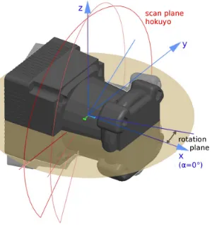
The 3D-Mirror-Pre-Filter was designed for 3D multi-echo laser scanners. In following work a rotating Hokuyo UMT-30LX-EW is used, cf. Figure 2. The scanner rotates around the z-axis which is marked by a beige filled semicircle in Figure 3. The scanning plane of the Hokuyo is in parallel with the z-plane and marked by red line semicircle. Therefore, at one data take of the Hokuyo the amount of points in theβ-angle is fixed toNβ = 1080. The amount of data takes on theα-angle varies with the speed of the scanner.
N=r·Nβ (1)
where N= total amount of scan points r= amount data takes per half rotation Nβ= data takes per scan of Hokuyo
The ROS-node (ROS, 2016) of the 3D scanner (Hokuyo3D-node) delivers a tupleP~after the scanner has rotatedα= 180◦.P~ con-sists two datasets~e1and~e2resulting from the first and the second
echo of the scanner. The pre-filter is implemented as a ROS-node as well and is publicly available as open-source packages at
http://www.github.com/autonohm/ohm_mirror_detector_ 3D.git.
~
with
e= point cloud with corresponding attributes d= distance from point to scanner
x, y, z= coordinates α= angle scanning plane ~
n0= surface normal vector
I= intensity m= mask
i= number of point k= number of echo
Figure 2: Rotating Hokuyo UTM-30LX-EW multi-echo laser.
Figure 3: Koordinate system and scannig plane of rotating Hokuyo UTM-30LX-EW.
2.3 Approach
Algorithm 1 shows the sequence of the 3D-Mirror-Pre-Filter-node. As soon as it receives a point cloud tupleP~from the Hokuyo3D-node subsequently Algorithm 1 is processed. First, erroneous dis-tance values and outliers get filtered. Then discontinuities in the echoes of each scan point inP~2are identified. Only in the case of
a positive identification the approach accesses a subsequence and
searches inP~2 for planar, square objects. If objects are located,
the function ’cleanScanTuple()’ cleans the point cloud tupleP~4.
Finally, the resulting point cloud tuplePout~ is broadcasted. The following subsections 2.3.1 – 2.3.7 describe the functions of Al-gorithm 1 in detail.
Algorithm 1 3D-mirror-pre-filter
Input: P~: ~
P includes the scan clouds with points and their corre-sponding attributes of Echo 1 and Echo 2. Each pointpi has a distancedi, an angleαi, xyz-coordinates, a normal-vector~n0i, an intensityIi, and a maskmi.
Output: Pvalid,surface,affected~ :
The messagePvalid~ includes the valid scan points with their corresponding attributes and scan points on the surface (d, α, xyz,~n0,I, andm). Psurface~ includes the scan points,
located on the surface of the transparent or specular re-flective object, with their corresponding values. Paffected~ includes the scan points, located behind the surface of the transparent or specular reflective object, with their corre-sponding values.
1: procedure3D-MIRROR-PRE-FILTER
2: Pin~ ←receiveScanTuple(P~)
12: sendScanTuple(Pout~ )
end
2.3.1 Function:receiveScanTuple(P~)
The functionreceiveScanTuple() awaits incoming messages, containing a tupleP~ of point clouds of Echo 1 (~e1( and Echo 2
(~e2) with their corresponding attributes, from the
Hokuyo3D-node and stores the tuple locally asPin~ . Besides, it sets a mask for Echo 1 and Echo 2 of every point. This maskmcontains the type of object(m= ’unchecked’). The mask is used to dis-tinguish between the different types of points. Following mask values can be assigned:
• ’unchecked’ is used for points which are not checked yet. This is the standard value for every incoming point.
• ’validPoint’ is used for valid scan points which are not af-fected by any specular reflective or transparent influence.
• ’errorSurface’ is used for points located on a specular re-flective or transparent object surface. The type of the caus-ing object is not identified yet.
• ’nanPoint’ is used for invalid points which are filtered out, e.g., from thethresholdFilter()- or theoutlierFilter()-function.
• ’reflectiveSurface’ is used for points located on an object with specular reflective surface properties like mirror or shiny metal.
• ’transparentSurface’ is used for points located on an object with transparent surface properties such as glass.
• ’behindReflective’ is used for points behind an object with specular reflective surface properties.
• ’behindTransparent’ is used for points behind an object with transparent surface properties.
2.3.2 Function:distanceThresFilter(P~in,dmin,dmax)
The measuring distance of a Hokuyo laser scanner is between 0.23 m and 30.0 m. Values out of this range are incorrect. There-fore, the functiondistanceThresFilter()masks values belowdmin and abovedmaxas ’nanPoint’. The cleaned point cloud is stored asP~1.
2.3.3 Function:outlierFilter(P~1,ninlier,r, ’unchecked’)
Measurements are always noisy. That is why the function out-lierFilter()searches for each scan pointpi (i = 0· · ·N) in a radiusrfor neighbours. If there are less thanninlierneighbours the resulting maskmiof the pointpiis set to ’nanPoint’. This eliminates points caused by jumping edges or other outliers. The function input variable ’unchecked’ is used as a mask to choose the favoured set of points inPx~ . This is necessary since the func-tion is used in a later step as well.
2.3.4 Function:identifyReflections(P~2,dthres,r, ’errorSurface’)
The identification of specular reflective and transparent objects is done by comparing each pointpiits distancesd1,iandd2,iand sets the maskmiof this point.
di=|d1,i−d2,i| (4)
where d= distance of point
s= difference of point distances of Echo 1 and Echo 2 m= objectType mask
i= number of point
Following all points on the object surface ofP~3 get cleaned by
the functionoutlierFilter()-filter. Therefore, the function input variable is set to ’errorSurface’. The result is stored inP~4. The
amount of identified points is stored in the variablenaffected.
2.3.5 Function:separateObject(P~4,dthres plane,nobject)
Ifnaffected is greater thannobject the 3D-Mirror-Pre-Filter en-ters a subsequence and the function ’seperateObjects()’ starts to search for planar, square objects as shown in Algorithm 2.
First, the subfunctionidentifyObjects()extracts planes using the SAC-Segmentation of PCL (PCL, 2016). Following the corners of each plane are identified with the feature extractor of PCL. This function is based on a principal component analysis (pca-analysis) and returns the four corners and the dimensions of the plane.
Second, the subfunctionanalyzeObjectType()uses the extracted plane and the points masked as ’validPoint’ to identify the type of object. Hence, it extracts all points which are located behind the plane and back-projects them w.r.t. the plane. Then an Iterative-Closes-Point-algorithm (ICP) matches the back-projected point cloud with the ’validPoint’-point cloud. In case of a positive re-sult it is assumed that the plane is a reflective object and the func-tionanalyzeObjectType()returns ’reflectiveSurface’. In case the matching of the point cloud failed the returned value is ’ transpar-entSurface’.
Finally, the points which are assigned to a surface are masked to prevent double assignment. The functionseperateObject()stops searching for new object planes, if the amount of unmasked af-fected pointsnaffectedis smaller than the thresholdnobject.
Algorithm 2 seperateObject()
Input: P~4,dthres plane,nobject:
~
P4is the scan cloud tuple resulting from the function
outlier-Filter(). nobjectis the minimal amount of points to identify an object.dthres planeis the maximal allowed distance a point can be away from the plane.
Output: ~o: ~
ois a vector of objects with its properties (xyz-coordinates of corners, type of object, width, length, plane function pa-rameters).
functionSEPERATEOBJECT()
while(naffected≥nobject)do
~o←indentifyObjects(P~4,dthres plane,nobject)
mobjectType←analyzeObjectType(P~4,dthres plane)
mask(P~4)
end
2.3.6 Function:cleanScanTuple(P~4,~o,dthres plane,dthres visionCone)
The functioncleanScanTuble()searches the entire tupleP~4and
checks each pointpi, if the point is part of an object surface, be-hind an object surface, or not affected at all. If pi is not part of an object surface the function assigns the objectType-mask mi =’validPoint’. Ifpiis part of an object surface or behind an object surface the function assigns themibased on the type of objectojas shown in Algorithm 3.
Algorithm 3 cleanScanTuple()
Input: P~4,~o,dthres plane,dthres visionCone:
~
P4is the point cloud tuple resulting from the function
seper-ateObject(). dthres plane is the maximal allowed distance a point can be away from the object surface. dthres visionConeis the distance to extend the vision cone.
Output: Pout~ : ~
functionCLEANSCANTUPLE()
for(j,j < NamountObjects,j+ +)do for(i,i < NscanSize,i+ +)do
c←checkVisionCone(dthres plane,dthres visionCone)
ifc==’onSurface’then
ifmobjectTye==’unchecked’then
mi,objectType←’errorSurface’
else ifmobjectTye==’refSurface’then
mi,objectType←’reflectiveSurface’
else ⊲ mobjectTye==’transparentSurface’ mi,objectType←’transparentSurface’
else ifc==’behindSurface’then ifmobjectTye==’unchecked’then
mi,objectType←’behindErrorS’
else ifmobjectTye==’reflectiveSurface’then
mi,objectType←’behindReflective’
else ⊲ mobjectTye==’transparentSurface’ mi,objectType←’behindTransparent’
else
⊲point outside of vision cone or in front of the surface mi,objectType←’validPoint’
end
2.3.7 Function:sendScanTuple(Pout~ )
The last function sendScanTuple()sends out Pout~ respecting the objectType-mask. Points assigned as ’validPoint’, ’ errorSur-face’, ’reflectiveSurface’, ’transparentSurface’, ’ behindTranspar-ent’ are send out together. Points assigned as ’behindReflective’ are first back projected to their origin and then added to the scan message. Points assigned as ’error’ and ’nanPoint’ are excluded. Hence, a following mapping algorithm uses a refined point cloud for mapping.
2.4 Experiments and Results
This chapter consists four experiments to demonstrate the usabil-ity of the 3D-Reflection-Pre-Filter Approach. Experiment 1 uses an empty room containing a mirror, Experiment 2 uses a stairway with a glass door, Experiment 3 uses a empty room containing two mirrors, and Experiment 4 applies the approach in a office room containing a mirror. All mirrors are unframed, planar and square. The scanner was used stationary without a mapping mod-ule.
2.4.1 Experiment 1: Empty room with a mirror
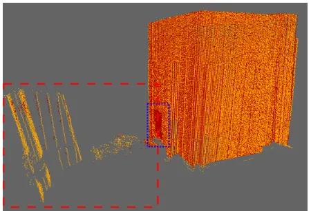
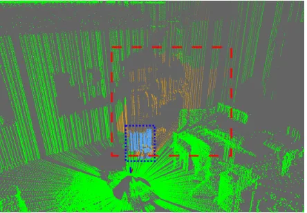
Experiment 1 was designed to demonstrate the identification of a square mirror in a defined area. The unframed mirror was lean-ing on the door. The scanner was placed on a table in the middle of an empty room. Figure 4 shows the resulting point cloud mes-sage after the scanner has finished a half rotation (180◦). The scan points of Echo 1 are coloured red and the scan points of Echo 2 are coloured orange. Both echoes show points on the mir-ror plane as well as behind the mirmir-ror plane. Their location is marked by a red broken line rectangle while the mirror location is marked by a blue dotted line rectangle.
Figure 4: Scan of an empty room. Points of Echo 1 are orange and points of Echo 2 are red.
Points behind the mirror are unwanted since they represent a mir-rored object. Since both echoes contain points behind the plane, it is not possible to choose simply one single echo for mapping to prevent the errors.
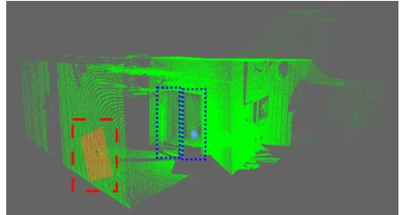
Figure 5 shows the resulting scan after the 3D-Reflection-Pre-Filter was applied. The valid scan points (green) and points on the mirror (turquoise) represent real objects. Therefore they are forwarded to a mapping module. The points behind the mirror plane are coloured orange. These points are displaced by the mir-ror effect. Their location should be in front of the mirmir-ror. That is why they are erased from the original point cloud. Hence, a mapping module will not map these points anymore. The real mirror dimensions are60cm×40cm while the detected mirror dimensions are60.5cm×41.9cm. This is very close w.r.t. the precision of the Hokuyo (±3cm between0.1−10m (Hokuyo, 2016)).
Figure 5: Cleaned scan after the 3D-Mirror-Detector-Pre-Filter was applied. Green colored are valid points, turquoise colored are points on the mirror plane, and orange are points behind the mirror plane
Figure 6: Cleaned scan from the side of the mirror plane. Points on the mirror plane are turquoise, and points behind the mirror plane are orange. The ”thickness” of the mirror depends on the chosen threshold.
2.4.2 Experiment 2: Stairway with a glass door
The second experiment was designed to show the applied 3D-Reflection-Pre-Filter in a stairway with a glass door. The distance of the scanner to the glass surface was similar to the distance of the scanner to the mirror surface in Experiment 1. Figure 7 shows the result after the approach processed the point cloud.
Figure 7: Cleaned scan of stairway with a glass door. Valid points are green, points on the glass facade plane are turquoise, and points behind the glass facade plane are orange.
Points located on the glass surface are coloured turquoise and marked by a blue dotted line rectangle. Points located behind the surface are coloured orange and marked by a red broken line rectangle. The size of the glass surface was bigger than the mirror in Experiment 1. It is obvious that the identified surface size is smaller. Besides, the shape of the recognised area is round, cf., Figure 8. This results from the different behaviour of transparent and reflective surfaces. The center point of the detected area in Figure 8 was hit perpendicular by the laser beam while the outer points were hit from the maximal recognisable angle of glass. This confirms results described by Koch et al. (?).
Since the 3D-Reflection-Pre-Filter assumes planar rectangle ob-jects it spans up a rectangle viewing cone. That is why the points behind the glass surface show a rectangle shape. The size of the glass surface was determined to be31.1cm×23.9cm. The real door had two glass surfaces each88cm×198cm. The detected glass area was around the perpendicular hitting laser beam.
The identification of the surface type by the function identifyOb-jects()is correct. Hence, all points (green, turquoise, and orange) remain in the point cloud and get forwarded to the mapping mod-ule. This experiment confirms the need of a post filter module as it was described by Koch et al. (Koch et al., 2016). Nevertheless,
Figure 8: Cleaned scan of the glass facade. Points on the glass facade plane are turquoise, and points behind the glass facade plane are orange.
at 3D point clouds it is possible to identify objects already in the first step, at pre-filtering. Despite, a post filter will improve the mapping. If the glass surface was bypassed it can be modulated more accurate. However, it might not cover the complete surface since the required angle range to detect the object is not reached. Therefore, the surface is not mapped completely. Even than, most time glass surfaces are vertical. As a result, the recognised glass surface is in front of the robot. That is why the robot will recog-nise the surface as a obstacle blocking it‘s pass. Hence, the robot will not navigate into it.
2.4.3 Experiment 3: Rooms with two mirrors
In Experiment 3 two mirrors are placed into two connected rooms. The mirrors are planar, free standing and unframed. In compare to Experiment 1 the door behind the first mirror was opened. That is why it was free standing on the ground blow the scanner. The second mirror was hanging in an angle above the scanner. The dimensions of both mirrors are60cm×40cm. Figure 9 shows the resulting point cloud after the 3D-Reflection-Pre-Filter processed the incoming point cloud. Both mirrors are detected correctly (turquoise). The size of Mirror 1 (standing on the ground) was determined to be59cm×39cm and Mirror 2 (was hanging) was determined to be62cm×40cm. Neverthe-less, the result shows that the points on the planes are not as dense as the in Experiment 1. This is illustrated in Figure 10. Especially the hanging mirror shows this effect. The algorithm detecting the plane corners uses the outer points. That is why the size of the mirror is still close to it‘s real dimensions. Nevertheless, this can not be assured. Therefore, a post filter using multiple point clouds (from different positions) to determine the mirror plane will give more precise results.
Figure 10: Points on the identified mirror planes are turqoise and corrupted points behind the mirror planes are orange.
2.4.4 Experiment 4: Office room with a mirror
The last experiment applies the Approach to an office room with a mirror. The60cm×40cm sized mirror was unframed and free standing, cf. Figure 11 and Figure 12. The mirror (turquoise) and the corrupted points (orange) which are erased from the orig-inal point cloud are shown in Figure 13. Similar to Experiment 4 the density of points on the plane varies. Besides, some area on the ground was also detected and assigned to the mirror plane. Reflections on the ground plane are possible and therefore they should be detected. Nevertheless, they should be assigned to an separate object plane. Here, they are close to the mirror. Be-cause of the chosen thresholds the algorithm does not split the plane into two objects. The identified dimensions of the mirror
64cm×57cm. Since the object is detected greater than it‘s real dimensions it will erase more points than necessary. However, it is favoured to map less points than corrupted points.
Figure 11: Cleaned scan of office room with a mirror. Valid points are green, points on the mirror plane are turquoise, and points behind the mirror plane are orange.
3. CONCLUSIONS AND FUTURE WORK
This paper presents the 3D-Reflection-Pre-Filter Approach to pre process point clouds of a 3D multi-echo laser scanner to reduce transparent and specular reflective influences. The approach searches the point clouds from the Hokuyo-3D-node for mismatches in distance between the corresponding echoes. On occurance these points get extracted and a function searches for planar obstacles. Following, points behind the object surface are back projected and fitted by an ICP algorithm to identify the type of the surface. Finally, all points are processed and masked according on their location and object type. Points behind the surface are removed, if they are influenced by an reflective object. All other points remain in the point cloud since they are valid scan points.
Figure 12: Cleaned scan of office room with a mirror from the side. Valid points are green, points on the mirror plane are turquoise, and points behind the mirror plane are orange.
Figure 13: Points on the Identified mirror plane are turqoise and corrupted points behind the mirror are orange.
Four experiments were made to demonstrate the usability of this approach. In the first experiment a mirror was detected in an empty room. It’s measured size was close to the size of the real mirror. The second experiment was conducted by an glass area. This experiment showed constrains since the detected glass area was smaller than the real glass surface. This contains two prob-lems: First, the glass was not seen completely; Second, the glass is only occasional visible. In the third experiment two mirrors were placed in an empty room. Both were located and identi-fied. Nevertheless, the experiment showed that the density on the surface varies. The final experiment applies the 3D-Reflection-Pre-Filter in an office room with a free standing mirror. The mir-ror was localised and identified. Some reflections on the ground are assigned to the mirror as well. That results from the chosen thresholds. The experiments show that for single point clouds the detection of specular reflective and transparent objects in 3D is possible. It is more reliable in 3D as in 2D. Nevertheless, collect the data of multiple point clouds and post-filter them as soon as the object was bypassed should pursued.
REFERENCES
Foster, P., Sun, Z., Park, J. J. and Kuipers, B., 2013. Visagge: Vis-ible angle grid for glass environments. In: Robotics and Automa-tion (ICRA), 2013 IEEE InternaAutoma-tional Conference on, pp. 2213– 2220.
Hokuyo, 2016. Hokuyo 30lx-ew. https://www.hokuyo-aut.jp. (15 Okt. 2016).
K¨ashammer, P.-F. and N¨uchter, A., 2015. Mirror identification and correction of 3d point clouds. ISPRS - International Archives of the Photogrammetry, Remote Sensing and Spatial Information Sciences XL-5/W4, pp. 109–114.
Koch, R., May, S., Koch, P., K¨uhn, M. and N¨uchter, A., 2016. De-tection of specular reflections in range measurements for faultless robotic slam. In: L. P. Reis, A. P. Moreira, P. U. Lima, L. Mon-tano and V. Muoz-Martinez (eds), Robot 2015: Second Iberian Robotics Conference, Advances in Intelligent Systems and Com-puting, Vol. 417, Springer International Publishing, pp. 133–145.
Koch, R., May, S., Murmann, P. and Nchter, A., 2017. Iden-tification of transparent and specular reflective material in laser scans to discriminate affected measurements for faultless robotic {SLAM}. Robotics and Autonomous Systems 87, pp. 296 – 312.
PCL, 2016. Pcl. http://pointclouds.org. (20 Sep. 2016).
ROS, 2016. Ros. http://www.ros.org. (20 Sep. 2016).
Yang, S.-W. and Wang, C.-C., 2008. Dealing with laser scanner failure: Mirrors and windows. IEEE International Conference on Robotics and Automation ICRA pp. 3009–3015.