JAVA-LIBRARY FOR THE ACCESS, STORAGE AND EDITING OF
CALIBRATION METADATA OF OPTICAL SENSORS
M. Firlej a, W. Kresse b
a
73-110 Stargard Szczeciński, Poland – [email protected] bPolitechnika Koszalińsk
a, 75-453 Koszalin, Poland – [email protected]
Commission I, WG I/1 or I/2 or I/3
KEY WORDS: Calibration, Airborne sensors, Metadata, Software interface, Java
ABSTRACT:
The standardization of the calibration of optical sensors in photogrammetry and remote sensing has been discussed for more than a decade. Projects of the German DGPF and the European EuroSDR led to the abstract International Technical Specification ISO/TS 19159-1:2014 “Calibration and validation of remote sensing imagery sensors and data – Part 1: Optical
sensors”.
This article presents the first software interface for a read- and write-access to all metadata elements standardized in the ISO/TS 19159-1. This interface is based on an xml-schema that was automatically derived by ShapeChange from the UML-model of the Specification. The software interface serves two cases. First, the more than 300 standardized metadata elements are stored individually according to the xml-schema. Secondly, the camera manufacturers are using many administrative data that are not a part of the ISO/TS 19159-1. The new software interface provides a mechanism for input, storage, editing, and output of both types of data. Finally, an output channel towards a usual calibration protocol is provided. The interface is written in Java.
The article also addresses observations made when analysing the ISO/TS 19159-1 and compiles a list of proposals for maturing the document, i.e. for an updated version of the Specification.
1. INTRODUCTION
The origin of the ISO/TS 19159-1 “Calibration and validation of remote sensing imagery sensors and data – Part 1: Optical sensors” was a demand for a standardized sensor calibration procedure defined by the camera manufacturers. This demand was channelled by the European Spatial Data Research (EuroSDR) and other organizations. The ISO Technical Specification was the final conclusion of this development.
Photogrammetry and remote sensing belong to the world of geographic information (KRESSE & FADAIE 2004). Therefore, the calibration standard became a part of the ISO/TC (Technical Committee) 211 “Geographic
information / Geomatics”. Within TC 211 the development was associated to WG (Working Group) 6
“Imagery” (ISO/TC 211 2016).
The project team consisted of members from Europe, North America, China and Australia, As usual, the work on an International Standard or on a Technical Specification pools the ideas of stakeholders worldwide, and thus modifying or advancing the original proposal. However, in the case of the calibration of optical sensors the European based original work covered the vast majority of the requirements of the Technical Specification. The ISO/TS 19159-1 was published in 2014.
2. TECHNICAL SPECIFICATION
The main parts of the ISO/TS 19159-1 are the chapters 6 calibration and 7 documentation. The annexes contain a data dictionary for every individual attribute and information about the distortion models.
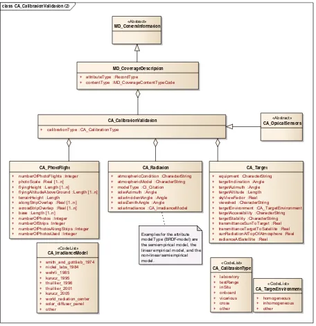
The content of the standard is expressed by class diagrams according to the Unified Modeling Language (UML). Figure 1 shows the top classes of the Specification.
From the modelling point of view the ISO/TS 19159-1 is a specialization of the metadata-standard for geographic information ISO 19115-1 (indicated by class-names beginning with MD) (ISO 19115-1 2014). In essence, the ISO/TS 19159-1 defines a set of metadata for calibration, but no calibration procedures. Talks with the camera manufacturers showed that their internal procedures are so diverse and partly unpublished that a common standard was deemed not possible.
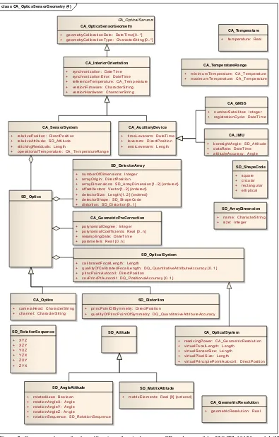
The Figure 2 presents the classes and attributes of the calibration of geometry. A similar diagram exists for the radiometric case. The ISO/TS 19159-1 defines a total of 341 classes and attributes. Following the ISO/TC 211 rules the UML class-diagrams of the calibration standard are created and maintained by the software program Enterprise Architect, developed by the company Sparx Systems (SPARX 2016).
Figure 1. Top-level class model of the ISO/TS 19159-1 “Calibration and validation of remote sensing imagery sensors and data – Part 1: Optical sensors” (ISO/TS 19159-1 2014)
class CA_CalibrationValidation (2)
«CodeList» CA_CalibrationType
+ laboratory + testRange + inSitu + onboard + vicarious + cross + other
«CodeList» CA_TargetEnv ironment
+ homogeneous + inhomogeneous + other CA_PhotoFlight
+ numberOfPhotoFlights :Integer + photoScale :Real [1..n] + flyingHeight :Length [1..n]
+ flyingAltitudeAboveGround :Length [1..n] + terrainHeight :Length
+ alongStripOverlap :Real [1..n] + acrossStripOverlap :Real [1..n] + base :Length [1..n] + numberOfPhotos :Integer + numberOfStrips :Integer
+ numberOfPhotosAlongStrips :Integer + numberOfPhotosUsed :Integer
CA_Radiation
+ atmosphericCondition :CharacterString + atmosphericModel :CharacterString + modelType :CI_Citation + solarAzimuth :Angle + solarIncidentAngle :Angle + solarZenithAngle :Angle + solarIrradiance :CA_IrradianceModel
CA_Target
+ equipment :CharacterString + targetInclination :Angle + targetAzimuth :Angle + targetAltitude :Length + skyViewFactor :Real + viewshed :CharacterString
+ targetEnvironment :CA_TargetEnvironment + targetAccessibility :CharacterString + targetStability :CharacterString + transmittanceSunToTarget :Real + transmittanceTargetToSatellite :Real + sunRadiationAtTopOfAtmosphere :Real + radianceAtSatellite :Real
CA_CalibrationValidation
+ calibrationType :CA_CalibrationType
MD_Cov erageDescription
+ attributeType :RecordType
+ contentType :MD_CoverageContentTypeCode «Abstract»
MD_ContentInformation
«Abstract» CA_OpticalSensors
«CodeList» CA_IrradianceModel
+ smith_and_gottlieb_1974 + nickel_labs_1984 + wehrli_1985 + kurucz_1995 + thuillier_1996 + thuillier_2001 + kurucz_2005 + world_radiation_center + solar_diffuser_panel + other
Figure 2. Geometry classes for the calibration of optical sensors, SD = classes of the ISO/TS-19130-model (ISO/TS 19130 2010), CA = classes of the ISO/TS-19159-1-model (ISO/TS 19159-1 2014)
class CA_OpticsSensorGeometry (4)
CA_OpticalSensors CA_OpticsSensorGeometry
+ geometryCalibrationDate: DateTime[0..*] + geometryCalibrationType: CharacterString[0..*]
CA_InteriorOrientation
+ synchronization: DateTime + synchronizationError: DateTime + referenceTemperature: CA_Temperature + versionFirmware: CharacterString + versionHardware: CharacterString
CA_SensorSystem
+ relativePosition: DirectPosition + relativeAttitude: SD_Attitude + stitchingResiduals: Length
+ operationalTemperature: CA_TemperatureRange
CA_AuxiliaryDev ice
+ timeLeverarm: DateTime + leverarm: DirectPosition + errorLeverarm: Length
SD_Optics
CA_GNSS
+ numberSatellites: Integer + registrationCycle: DateTime
CA_IMU
+ boresightAngle: SD_Attitude + dataRate: DateTime + attitudeAccuracy: Angle
SD_Distortion
+ princPointOfSymmetry: DirectPosition
+ qualityOfPrincPointOfSymmetry: DQ_QuantitativeAttributeAccuracy
CA_Temperature
+ temperature: Real
SD_OpticalSystem
+ calibratedFocalLength: Length
+ qualityOfCalibratedFocalLength: DQ_QuantitativeAttributeAccuracy [0..1] + princPointAutocoll: DirectPosition
+ covPrincPtAutocoll: DQ_PositionalAccuracy [0..1] SD_DetectorArray
+ numberOfDimensions: Integer + arrayOrigin: DirectPosition
+ arrayDimensions: SD_ArrayDimension[1..2] {ordered} + offsetVectors: Vector[1..2] {ordered}
+ detectorSize: Length[1..2] {ordered} + detectorShape: SD_ShapeCode + distortion: SD_Distortion[0..1]
SD_ArrayDimension
+ name: CharacterString + size: Integer
+ resolvingPower: CA_GeometricResolution + virtualFocalLength: Length
+ virtualSensorSize: Length + virtualPixelSize: Length
+ virtualPrinciplePointAutocoll: DirectPosition CA_GeometricPreCorrection
+ polynomialDegree: Integer + polynomialCoefficients: Real [0..n] + resamplingDate: DateTime + parameters: Real [0..n]
CA_Optics
+ cameraHead: CharacterString + channel: CharacterString
CA_TemperatureRange
+ minimumTemperature: CA_Temperature + maximumTemperature: CA_Temperature
CA_GeometricResolution
+ geometricResolution: Real SD_Attitude
SD_AngleAttitude
+ rotatedAxes: Boolean + rotationAngleX: Angle + rotationAngleY: Angle + rotationAngleZ: Angle
+ rotationSequence: SD_RotationSequence
SD_MatrixAttitude
3. IMPLEMENTATION
3.1. Generation of the xml-schema-file
Conceptually, ISO-standards are abstract. Consequently, the ISO/TS 19159-1 only defines attributes, their properties like the data type, and their inter-relations. In theory, ISO-standards do not define, how the implementation shall look like. However, in computer technology it is a practical requirement that the implementation level is fully defined because otherwise programs do not function properly. Therefore, the ISO/TC 211 recommends an open-source program named ShapeChange that reads the project file of Enterprise Architect (*.eap) and writes the an xml-schema-file that has identical attributes and their properties (SHAPECHANGE 2015). This xml-schema-file defines the structure, the format, and other details of the xml-file that serves as a data container for all calibration attributes and their values. The program that is in the focus of this article creates such an xml-file based on the xml-schema-file, writes attribute-values to the xml-xml-schema-file, or reads those values back from the xml-file, and finally outputs the values to a generic calibration report document.
The ISO standard defines the technically required parameters for the calibration process. In addition, usually a calibration report contains administrative parameters that are not standardized by ISO but demanded by practical requirements of the calibration laboratory. Therefore, the program accesses two data sources, first the xml-file written according to the ISO-standard, and second an administrative file, that contains the additional parameters. The program was tested using the calibration report file of Microsoft Photogrammetry (now Vexcel Imaging GmbH).
3.2. Program development
In essence, the programming was straight forward. The only challenge was caused by the large number of attributes.
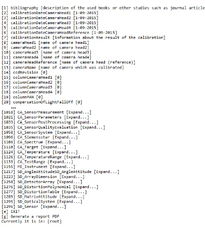
At its first start, the program assumes that an xml-file does not exist and thus creates such a file after the start, and sets default values for all attributes. In the other case, if at the program-start an xml-file with a correct format and content is found, this file is opened, its content read,
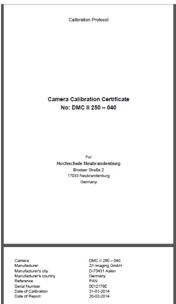
and copied to the computer’s memory. In both cases all attribute-values are available to the user while the program is running. A simple text-based user-interface allows updating every individual attribute-value under consideration of the rules defined in the standard (Figure 3). Before closing the program the attribute-values are written back to the xml-file which functions as a data container. The administrative file is processed in the same way. One of the functions of the program allows creating the calibration report out of the data that are presently set in the program (Figure 4).
3.3. Observations
The development of the program lead to the identification
when a written documentation, the ISO Technical Specification, is converted into a computer program for the first time. Examples of those errors were non-consistent spellings of parameter names and differences between class-diagrams and the data dictionary.
The main problem of the program ShapeChange was the creation of more than one parent nodes (entry-point) which makes the xml-schema file a-priori invalid. For the use of this xml-schema-file the multiple entry-points were manually corrected. In addition, some attributes were found that were not fully consistent with the standard. A few data types were missing.
Based on the xml-schema-file the xml file was created using the program Altova (ALTOVA 2015). During this process some other obstacles were met, again mostly related to attributes, their data types and further properties. Those ambiguities regarding names and inheritance were corrected manually.
3.4. Output
The project aimed at creating a camera calibration report based on the ISO/TS 19159-1. As said above, such a report provided by a calibration laboratory contains standardized as well as company-specific parameters. In order to match those need, two data storages were created, the above mentioned xml-file derived from the standard and a company-specific xml-file. The development aimed at relating as many as possible parameters of the camera calibration protocol to the attributes defined in the ISO Technical Specification and to minimize the number of parameters of the company-specific file.
Figure 4. Example for a calibration report output
4. CONCLUSIONS
The new program offers the implementation interface for the calibration standard of optical sensors (ISO/TS 19159-1 2014). This interface can be operated alone or may later be implemented in larger environments. It is generically structured. Therefore, it can be easily adapted to similar Specifications and be considered as a first in a series of programs that provide the implementation of other ISO Standards and Technical Specifications of which presently only the original abstract version exist. Examples are other calibration tasks and the georeferencing of sensors.
REFERENCES
ALTOVA, 2015. Altova, XMLSpy/ XML Editor. http://www.altova.com/xmlspy.html (2.5.2015).
ISO/TC 211 2016. ISO/Technical Committee 211 Geographic information / Geomatics. http://www.isotc211.org/ (9.4.2016).
ISO 19115-1, 2014. International Standard ISO 19115-1 Geographic information – Metadata – Part 1: Fundamentals. ISO, Geneva, Switzerland.
ISO/TS 19130, 2010. ISO/Technical Specification 19130 Geographic information – Imagery sensor models for geopositioning. ISO, Geneva, Switzerland .
ISO/TS 19159-1, 2014. ISO/Technical Specification 19159-1 Geographic information – Calibration and validation of remote sensing imagery sensors and data – Part 1: Optical sensors. ISO, Geneva, Switzerland.
KRESSE, W. & FADAIE, K., 2004. ISO Standards for Geographic Information. Springer, Heidelberg, Germany.
SHAPECHANGE, 2015. ShapeChange.
http://shapechange.net/about/ (13.5.2015).