GEOMETRIC STITCHING METHOD FOR DOUBLE CAMERAS WITH WE
A
K
CONVERGENCE GEOMETRY
Nan Zhoua, Hongyan Ha, Yunfei Baoa,Chunyu Yuea, Kun Xinga, Shixiang Caoa
aBeijing Institute of Space Mechanics &Electricity, Beijing 100076, China
Commission VI, WG VI/4
KEY WORDS:Weak Convergence, Stitching, DEM, Block Adjustment, RFM
ABSTRACT:
In this paper, a new geometric stitching method is proposed which utilizes digital elevation model (DEM)-aided block adjustment to solve relative orientation parameters for dual-camera with weak convergence geometry. A rational function model (RFM) with affine transformation is chosen as the relative orientation model. To deal with the weak geometry, a reference DEM is used in this method as an additional constraint in the block adjustment, which only calculates the planimetry coordinates of tie points (TPs). After that we can use the obtained affine transform coefficients to generate virtual grid, and update rational polynomial coefficients (RPCs) to complete the geometric stitching. Our proposed method was tested on GaoFen-2(GF-2) dual-camera panchromatic (PAN) images. The test results show that the proposed method can achieve an accuracy of better than 0.5 pixel in planimetry and have a seamless visual effect. For regions with small relief, when global DEM with 1 km grid, SRTM with 90m grid and ASTER GDEM V2 with 30m grid replaced DEM with 1m grid as elevation constraint,it is almost no loss of accuracy. The test results proved the effectiveness and feasibility of the stitching method.
1. INTRODUCTION 1.1 General Instructions
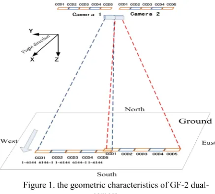
GF-1/2 is the first one to be launched by China's high resolution earth observation project, which can provide high accuracy data and satisfy various application requirements [1]. Multiple cameras are adopted by many high-resolution satellites of China to achieve a wide swath. The satellite carries two same push-broom high-resolution cameras, which includes a PAN charge-coupled device (CCD) array and a multispectral (MS) CCD array with ground sampling distance (GSD) of 0.81m and 3.24m, respectively. The PAN consists of five linear CCD arrays placed in a noncollinear manner on the focal plane with a certain overlap cross track between adjacent CCD arrays. Figure 1 shows the geometric characteristic of GF-2 camera, the angle between cameras is 2.01 degrees and a certain overlap cross track is 380 pixels, so its convergence geometry condition is very weak. In order to improve the efficiency of the high-resolution images application, it is necessary to provide a high quality image stitching product with uniform geometric precision. The seamless mosaic images without distortion are necessary for subsequent photogrammetry production, such as sub pixel stitching accuracy is the premise to ensure the accuracy of DEM production. The problem of how to make the high precision geometric stitching of the multiple cameras images becomes an urgent problem needed to be solved.
Figure 1. the geometric characteristics of GF-2 dual-camera
High-resolution satellites rarely use multiple cameras to achieve a wide swath and relevant technical documents and literature are found few. Several researchers focused on image stitching with weak geometry. Jcobsen et al. proposed a simple image shift method to stitch for the three CCD line-sensors of the IRS-1C satellite panchromatic camera, and the accuracy of the model is from 0.2 to 0.6 pixels in image space [2]. Zhang and Tang et al. used an inner field of view (FOV) stitching method based on virtual CCD line, ZY-3 and ALOS/PRISM images are used to verify the algorithm [3-4]. However, the potential error sources of the method are analysed deeply. The stitching error caused by elevation error cannot be ignored, especially for the elevation more than 300 meters,it will cause 1 pixel stitching error in push-broom direction [5].
In view of the above problems, and taking into account the small converge angle between the camera images, it may cause erroneous results or iteration failures during the block
The International Archives of the Photogrammetry, Remote Sensing and Spatial Information Sciences, Volume XLII-1/W1, 2017 ISPRS Hannover Workshop: HRIGI 17 – CMRT 17 – ISA 17 – EuroCOW 17, 6–9 June 2017, Hannover, Germany
This contribution has been peer-reviewed.
adjustment. We proposed a new geometric stitching method, which utilizes DEM-aided block adjustment to solve relative orientation parameters of each camera image for dual-camera with weak geometry. A RFM with affine transformation model is chosen as the relative orientation model. To deal with the non-convergence problem caused by weak geometry, a reference DEM is used in this method as an elevation constraint in the block adjustment, which only calculates the planimetry coordinates of TPs, then using the obtained affine transform coefficients to generate virtual grid, then updating the new RPCs to complete the geometric stitching.
2. PROPOSED SCHEME 2.1 RFM with Affine Transformation Model
Satellite photogrammetry has the characteristics of long focal length, narrow FOV and nearly parallel projection. High-resolution satellite image processing method are mainly based on the theoretically rigorous imaging geometry model, but there will be a strong correlation between the orientation parameters. Thus, its superiority has often been solved by many parameters, and the unstable numerical solution [6]. RFM is well known and widely used in the distribution and processing of satellite imagery, which has been proven to be very simple, fast, and stable. So, RFM is selected as the geometric model.
RFM uses the ratio of two cubic polynomials to describe the relationship between the image space and the object space as shown in (1). To maintain numerical precision, the object and image space coordinates will be normalized to (−1, +1) [6-7].
( , , )
To compensate for the systematic error of the RPCs, we use an affine transformation model to correct and refine RPCs in the image space [8].The coefficients for the affine transformation can be calculated from the GCPs. The equation for the affine transformation is
e
f
= affine coefficientsThe error equation can be established as follows:
where
V
= residual matrix for the RFM equationsA
= the design matrix which consists of partial derivatives of x, y to a0, a1, a2, b0, b1, b2,respectivelyB
= the design matrix which consists of partial derivatives of x, y to X, Y, Z, respectivelys
= the correction vector of affine parameterst
= the correction vector of the unknown GCPsl
= the difference of the calculated and observed image point coordinates2.2 DEM-Aided Intersection for Ground Points
To deal with the weak convergence geometry and small base-to-height ratio situation, a reference DEM is used as an additional constraint for the ground points. First, an initial elevation
Z
0 is given, and the corresponding planimetry coordinates0 0
( , )
X Y
are calculated by RPCs and affine transformation parameters. We interpolate a new elevationZ
1 from DEM with( , )
X Y
0 0 , Through iteration and interpolation, when the incremental value of the new elevation(
Z
i1
Z
i)
is smaller than a certain threshold, we attain an accurate result and overcome the problem of elevation error. The full procedure is demonstrated in Fig. 2[9-10].Fig.2 DEM-Aided Intersection for Ground Points
2.3 Update RPCs
We can solve the affine transformation parameters through iteration, and then updating RPCs. Specific steps are as follows:
1. Using the original RPCs and affine transformation parameters to generate the new virtual control points grid without system error, grid size is 10*10*5;
2. Using the virtual grid, update the new RPCs according to the L curve method [11].
3. Using the new parameter for the precision statistics in the object space and image space.
3. EXPERIMENTS AND ANALYSIS
3.1 Data Set
The test data were GF-2 level 1A standard products, including images and the corresponding RPCs. The geometric characteristic of GF-2 dual-cameras shows that the angle
The International Archives of the Photogrammetry, Remote Sensing and Spatial Information Sciences, Volume XLII-1/W1, 2017 ISPRS Hannover Workshop: HRIGI 17 – CMRT 17 – ISA 17 – EuroCOW 17, 6–9 June 2017, Hannover, Germany
This contribution has been peer-reviewed.
between cameras is 2.01 degrees, so the convergence geometric condition is very weak.
Images of two areas (Beijing and Henan Province in China) and the corresponding DEMs are introduced. The range of Beijing area is 116.02 ° E ~ 116.48 ° E, 39.71 ° N ~ 40.02 ° N. The terrain of the test site has about 500m relief. The range of Henan area is 112.91°E~113.37°E,34.21°N~34.53°N. The terrain of the site has about 1200m relief. This test area set up 21 ground control points (GCPs). The control data is extracted by artificial measurement from the reference digital orthophoto map (DOM) and DEM. The accuracy of the DEM is about 1m in height, and the planimetry accuracy of the DOM is about 1 m.
3.2 Test scheme
In order to compare and verify the accuracy of the stitching algorithm in different regions and different terrain condition, this paper mainly uses the following test scheme.
Experiment 1: The images of Henan area and the corresponding 1m resolution DEM are used with and without GCPs. The purpose is to verify the planimetry accuracy of method proposed in this paper. Comparing and analysing the accuracy of with and without GCPs by calculating the TPs residual error statistically in image space, and evaluating the stitching effect by overlap display.
Experiment 2: The images of two areas (Beijing and Henan) and different accuracy DEMs (include global DEM with 1 km grid, SRTM with 90m grid and ASTER GDEM V2 with 30m grid) are used without GCPs. The purpose is to verify the accuracy of DEM influence on stitching accuracy.
3.3 Experimental Results
3.3.1 The accuracy of stitching with and without GCPs:The images of Henan area are used to stitch according to experiment 1. The results of the test are shown in Table 1.
Table 1. Accuracy of stitching with and without GCPs
Test area GCPs CPs RMSE(m)
E N Plane
Henan 0 21 14.35 68.10 69.59
9 12 1.22 1.08 1.63
Table 1. Accuracy of stitching with and without GCPs
As shown in Table 1, the planimetry accuracy of stitching is 69.59m without GCPs, this result agrees with the previously reported accuracy. While the planimetry accuracy of stitching is 1.63m with 9 GCPs and the system error is eliminated effectively.
To verify the geometric consistency between images, the TPs residual in image space are statistics, as shown in Table 2.
Test area scheme TPs RMSE(pixel)
E N Plane
Henan with GCPs 18 0.42 0.49 0.65 without
GCPs 18 0.41 0.24 0.48
Table 2 Results of TPs residual
As shown in Table 2, the RMSE of TPs without GCPs is about 0.48 pixels and the RMSE of TPs with GCPs is about 0.65 pixels. The accuracy of stitching with GCPs is slightly lower than without GCPs. The artificial measurement accuracy of GCPs is difficult to achieve sub-pixel, therefore result in a slight
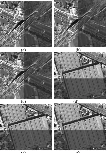
inconsistency in precision. In the course of adjustment, the poor accuracy GCPs will affect the network of the whole area. We can solve the affine transformation parameters through iteration, and update RPCs. Evaluating the stitching accuracy of images with new RPCs by overlapped display. The images are rescaled necessarily for a better visual effect. The stitching effect of Henan area is shown in Fig. 3. It can be seen that the accuracy of the overlap area has a seamless visual effect and there is no obvious misalignment phenomenon in the areas(roads, houses, bridges, mountains, and so on). The method proposed in this paper can ensure higher geometric consistency in the overlapped area, and skip the step of stitching line selection
(a) (b)
(c) (d)
Figure 3. Stitching effect of Henan test area. (a) and (b) across track stitching effect, and (c) and (d) along track stitching effect
3.3.2 The stitching accuracy with different DEMs test:
The images of two areas (Beijing and Henan) and different accuracy DEMs are used to stitch according to experiment 2. As shown in Table 3, it is almost no loss of accuracy for Henan test area, when global DEM with 1 km grid, SRTM with 90m grid and ASTER GDEM V2 with 30m grid replaced DEM with 1m grid as elevation control. Similarly, it can achieve consistent geometric accuracy for Beijing test areas. This is because the geometric characteristics of GF-2 dual-camera, which two cameras approximate vertical observation, projection error is very small for regions with small relief, so different DEMs have the same elevation control effect.
Test area DEM TPs RMSE
E N Plane
Henan 30m 18 0.46 0.21 0.51
90m 18 0.46 0.21 0.51
1000m 18 0.46 0.21 0.51
Beijing 30m 23 0.39 0.24 0.46
90m 23 0.39 0.24 0.46
1000m 23 0.39 0.24 0.46 Table 3. Results of stitching with different DEMs Figure 2 shows the visual effect of stitching with different DEMs-aided. In order to better show the effect visual of stitching, the image display grayscale. It can be seen that the
The International Archives of the Photogrammetry, Remote Sensing and Spatial Information Sciences, Volume XLII-1/W1, 2017 ISPRS Hannover Workshop: HRIGI 17 – CMRT 17 – ISA 17 – EuroCOW 17, 6–9 June 2017, Hannover, Germany
This contribution has been peer-reviewed.
accuracy of the overlap area has a seamless visual effect and there is no obvious misalignment phenomenon in the areas (roads, houses, bridges, mountains).
(a) (b)
(c) (d)
(e) (f)
Figure 4. Stitching effect of test areas. (a) across track stitching effect with 30m DEM, (b) across track stitching effect with 90m DEM, (c) across track stitching effect with 1km DEM, (d) along track stitching effect with 30m DEM, (e) along track stitching effect with 90m DEM, (f) along track stitching effect with 1km
DEM
4. CONCLUSION
In this paper, a new geometric stitching method is proposed which utilizes DEM-aided block adjustment to solve relative orientation parameters of each camera image for dual-camera with weak convergence geometric. The panchromatic images of GF-2 dual-camera were tested and compared the stitching accuracy with different DEMs. After the full analysis of the experiment results, we conclude the following.
1. The proposed method can achieve an planimetry accuracy of better than 0.5 pixel of the TPs and has a seamless visual effect. The test results proved the effectiveness and feasibility of the stitching method. 2. The non-convergence caused by weak convergence geometric is solvedby the reference DEM in the block adjustment.
3. For regions with small relief, it is almost no loss of accuracy for test areas, when global DEM with 1 km grid, SRTM with 90m grid and ASTER GDEM V2 with 30m grid replaced DEM with 1m grid as elevation control. The method proposed in this paper can ensure higher geometric consistency in the overlap area, and omit optimal stitching line selection step.
REFERENCES
[1]Bingxin Yang, Dongjing Cao. The technology innovation and Inspiration of GF-2 satellite high-resolution camera[J]. Spacecraft Recovery & Remote Sensing, 2015,36(4):10-15. [2]Jacobsen K. Hannover Univ. Geometric and information potential of IRS-1C PAN-images[J]. International Geoscience and Remote Sensing Synposium,1999,(1):428-430.
[3]Guo Zhang, Bin Liu, Wanshou Jiang. Inner FOV stitching algorithm of spaceborne optical sensor based on the virtual CCD line[J]. Journal of Image and Graphics,2012,17(6):696-701.
[4]Xinming Tang, Ping Zhou, Guo Zhang, et al. Research on a production method of sensor corrected products for ZY-3 Satellite[J]. Geomatics and Information Science of Wuhan University, 2014,39(3):288-294.
[5]Jun Pan, Fen Hu, Mi Wang. Inner FOV Stitching of ZY-1 02C HR Camera based on virtual CCD line[J]. Geomatics and Information Science of Wuhan University,2015,40 (4),436-443.
[6]GRODECKI J, DIAL G. Block adjustment of high-resolution satellite images described by rational polynomials[J]. Photogrammetric Engineering & Remote Sensing, 2003,69(1):59-68
[7]Li Zhang, Jixian Zhang, Xiangyang Chen, et al. Block adjustment with SPOT5 Imagery and sparse GCPs based RFM[J]. Acta Geodaetica et Cartographica Sinica,2009,38(4),302-310.
[8]Tangyang Wang, Guo Zhang. Block ortho-rectification for satellite images[J]. Geomatics and Information Science of Wuhan University, 2014,39(7):838-842.
[9]Tangyang Wang, Guo Zhang. Block ortho-rectification for satellite images[J]. Geomatics and Information Science of Wuhan University, 2014,39(7):838-842.
[10]T. A. Teo, L. C. Chen, C. L. Liu, Y. C. Tung, et al. DEM-aided block adjustment for satellite images with weak convergence geometry[J]. IEEE Trans. Geosci. Remote Sens., vol. 48, no. 4, pp. 1907–1918,Apr. 2010.
[11]Xiuxiao Yuan, Xianyong Lin. A method for solving rational polynomial coefficients based on ridge estimation[J]. Geomatics and Information Science of Wuhan University, 2008,33(11):130-133.
The International Archives of the Photogrammetry, Remote Sensing and Spatial Information Sciences, Volume XLII-1/W1, 2017 ISPRS Hannover Workshop: HRIGI 17 – CMRT 17 – ISA 17 – EuroCOW 17, 6–9 June 2017, Hannover, Germany
This contribution has been peer-reviewed.