PRECISE LASER-BASED OPTICAL 3D MEASUREMENT OF WELDING SEAMS
UNDER WATER
T. Ekkel, J. Schmik, T. Luhmann, H. Hastedt
Institute for Applied Photogrammetry and Geoinformatics, Jade University of Applied Sciences Oldenburg, Germany [email protected]
Commission V
KEY WORDS: Calibration, Camera, Multi-Media, Optical, Photogrammetry, Tracking, Underwater
ABSTRACT:
This paper deals with the development of a measuring procedure and an experimental set-up (stereo camera system in combination with a projecting line laser and a positioning unit) which are intended to detect the surface topography, particularly of welds, with high accuracy in underwater environments. The system concept makes provision for the fact that the device can be positioned in space and manipulated by hand. The development, optimization and testing of the system components for surface measurements as well as calibration and accuracy evaluations are the main objectives within this research project. Testing procedures and probes are constructed and evaluated to verify the results. First results will be shown, where the test objects are underwater. The development considers conditions for a future adaption to underwater use.
1. INTRODUCTION
Up to now no optical assisted testing systems are known for the automatic detection of the surface topography and geometry of welding seams in underwater use. The increasing construction of off-shore buildings like platforms, ports and wind power plants as well as installations in harbours and industry require further developments in terms of underwater welding and inspection techniques. The 3D acquisition of welding seams is needed for documentations and quality control by instantiating repairs and recurring inspections.
Different investigations and developments of photogrammetric 3D measurement techniques in underwater conditions are given by Höhle (1971), Kotowski (1987) or Korduan et al. (2003). Harvey et al. (2003), Korduan and Lämmel (2004) and Shortis et al. (2000) report on investigations of 3D stereo-measuring systems for underwater conditions but focussing on lower accuracy requirements.
In order to provide high measuring sensitivity and reliability new developments are necessary to create a suitable assisted and automated testing technique with respect to the measuring task and its corresponding conditions. Due to the targeted underwater application high demands in terms of stability, accuracy and multi-media imaging model must be fulfilled by the measuring system. Extended mathematical models have to be developed for optical imaging and high-precision 3D reconstruction for a system that allows for multi-media optical interfaces based on previous investigations, e.g. published by Kotowski (1987), Mulsow (2010) or Maas (2014).
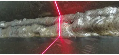
The desired measuring concept consists of a system for 3D measurement of welding seams based on a multi-camera set-up with projected laser lines (Figure 1). One part of the system is composed by the measuring unit of the laser profiles while a second component is used to position the device, i.e. to provide the absolute orientation of single profiles within a common coordinate system. The positioning device can be utilised, in principle, by mechanical means as given by Vilaca et al. (2006)
and Klimentjew et al. (2010) or, as done in this case, be provided by an additional camera system.
Figure 1. Projected laser line on a welding seam (hollow seam)
In principle, the welding seam geometry can be measured by a laser line sensor consisting of one camera and a laser plane. The method is widely used and well known (Fraunhofer, 2008). Mc Ivor (1999) discusses calibration possibilities for laser line sensors. One benefit of such systems is given by the fact that they can be configured individually. As a drawback system calibration under water is not trivial. Since the measurement principle does not allow for redundant information, errors of laser plane calibration directly affect the measurement result without control. In addition, occlusions can occur for the camera.
Main objective of the project is the investigation of different concepts for camera and laser arrangements according to given specifications. As a result, a stereo camera system with laser line projection has been defined. The advantages of such a set-up are given by higher redundancy, better resolution and accuracy, and the use of standardized photogrammetric calibration methods. The current research is based on extended experiences in camera technology and calibration (Luhmann et al., 2014), and in modelling and calibration of 3D measuring devices as they will be applied for this work (Hastedt et al., 2005; Luhmann et al., 2008).
2. SYSTEM CONCEPT
In order to reconstruct the surface geometry a stereo camera system with a projecting line laser (stereo laser-profile system) is developed. An optical positioning component is added to the systems concept to define the orientation of each 3D laser profile in a global object coordinate system. This enables the definition of the surface in three-dimensional object space. In a first stage, the concept is investigated and a demonstrating system (demonstrator) is developed. The demonstrator including the positioning component is evaluated under laboratory conditions. In a further project stage the stereo camera system will be modified for underwater use under real conditions.
The systems accuracy mainly depends on the resolution of the cameras (defining the amount of measurable points in object space) and the accuracy of the positioning unit. In addition, factors like the configuration of the stereo camera and line laser, the measuring strategy of the profile lines and the quality of the systems calibration have to be considered.
A high measurement resolution in the order of 1/10 mm shall be achieved by the introduced stereo laser-profile system. In the ideal case welding pores and cracks can then be detected. The wider objective is to provide a documentation of the surface topography of the welding seam and to enable a subsequent visual testing of the 3D surface.
2.1 Stereo laser-profile system
In order to measure the surface geometry a stereo camera system is combined with a projecting line laser. The line laser is used as structural light and therefore, in contrast to its function within a laser triangulation system, the projected laser plane does not have to be calibrated. Within the stereo images homologous points representing the projected laser line are automatically detected. The resulting 3D profile based on the homologous points is calculated by spatial intersections. The six degrees of freedom (6DOF) that define the three-dimensional orientation of each 3D profile in object space are determined by the positioning component.
High accuracy requirements with respect to the surface topology of a welding seam induce alike requirements to the stereo camera system. A high resolution of the cameras is needed as well as a minimum measuring frequency of 20 Hz to allow for an adequate scanning speed. Addressing the future underwater use the working distance of the measuring head has to be minimised. This helps to minimise the thickness of water and therefore unpredictable circumstances, e.g. caused by turbulences or particles. The shorter the working distance the higher the achievable resolution in object space. Additionally a convergent arrangement of the cameras (30°) is applied to reduce shades on the laser line due to buckles and holes on the surface.
The measuring task requires high qualitative line laser optics. An even, homogenous brightness on the length and width of the laser line is necessary for the laser projection. Favorable for underwater purposes is a high laser power in order to compensate for a loss of brightness due to the medium water and containing particles.
As reported by Bass et al. (2009 and Hildebrandt et al. (2008) the wavelength of the line laser should be in the green spectral band.Hence, it is a good compromise between high light energy
and absorption effects of the water caused by suspended loads and dissolved solids.
2.2 Positioning component
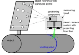
For the positioning approach the stereo laser-profile system and the positioning component (camera system) are physically assembled to a combined system building the measuring head. Then the positioning component acquires a fixed object reference (Figure). The 6DOF orientation in object space is provided by space resection, thus the measured 3D profile is also given in object space. In this case the positioning component can either be formed by a multi-camera system or a single-camera system. Using a single camera a suitable configuration of the object reference has to be chosen in order to gain a straightforward result (Luhmann, 2009).
A test measurement (repeated measurements of a target) shows an accuracy of 0.05mm in object plane and 0.15mm in the viewing direction of the measurement system (Ekkel et al., 2013).
Figure 2. Principle of the acquisition of the weld geometry with a stereo camera system in combination with a projecting line laser and a positioning unit
2.3 Development of the measuring head
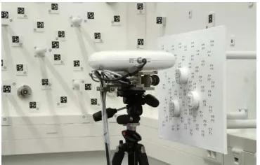
The stereo laser-profile system consists of two high resolution Basler Ace cameras (4MP, 25fps full resolution) from Basler AG (Basler, 2015). Both cameras are arranged with a convergence angle of 30° and a line laser module is mounted between them. Since an appropriate green laser was not available, a red laser line (635 nm) is used. For the positioning component an existing stereo-camera system CamBar B2 from AXIOS 3D is used (white housing, Figure 3), which is designed for optical tracking and positioning in three-dimensional object space. It is pre-calibrated and has a measurement range between 0.8m to 2.4m (AXIOS, 2015). Both camera systems are fixed on a stable bar perpendicularly, thereby a laterally fixed object reference can be measured.
Figure 3. Measuring head: stereo laser-profile system (two Basler Ace cameras and laser line module) in the bottom and positioning component above (stereo camera system CamBar, AXIOS 3D services, white housing).
2.4 System calibration
In order to calibrate the measuring head, i.e. to estimate the orientation of all optical components, both systems synchronously observe a calibrated object reference mounted to a wall (Figure 4). The relative orientation between the two stereo cameras is estimated within a bundle adjustment by using fixed pre-calibrated interior orientations.
Figure 4. Calibration of the camera system with a reference object on a wall
The calibration result shows an image measurement precision of 0.4µm, which is less than 0.1 – 0.2 pixel. The remaining standard deviation of the object coordinates are in the range of 0.03mm for the XY-plane and at 0.1mm for the viewing direction of the positioning camera. The resulting relative orientations are determined significantly and are reliably applicable.
2.5 Profile point determination
The measurement images of the stereo laser-profile system record the projected laser line which is deformed according to the object shape. The laser line should be only a few pixels wide and very homogenous without a speckle pattern.
(a) (b)
Figure 5. Laser line image with (a) obvious speckle noise and (b) reduced speckle noise on a thinner line
Figure 5a illustrates a grainy structure caused by the so called laser speckle or speckle granulation. A reduced speckle noise and a more homogeneous structure within the image are shown in Figure5b. The speckle noise is a natural feature of the laser light. If the laser light (coherent light) hits an uneven surface and the magnitude of the surfaces’ roughness is within the range of the laser’s wavelength interferences occur. These interferences lead to an extinction or gain in the light wave. The speckle noise then results from these interferences. Observing a laser line from different perspectives, as it is given by using a stereo-camera system, the speckle noise is presented with different characteristics (Meschede, 2008).
For the determination of the profile points a least-squares matching (LSM) approach is used (Bethmann and Luhmann, 2010). A best fit between two image patches is calculated along the corresponding epipolar line (Figure 6). Since LSM is
processed for normal case images the parameters of affine transformation for y (b0, b1, b2) are not introduced as unknowns for the adjustment. Otherwise matching of linear structures in y direction would not be reliable. Thus the simplified functional model is given:
) " , " ( " ) ' , ' (
' x y g x y
g =
' ' " a0 a1x a2y
x = + +
" " ky
y =
where g'(x',y') : image function in template g"(x",y") : image function in search image a0, a1, a2 : unknown parameters of
affine transformation
ky" : intercept of the corresponding
epipolar line
Figure 6. Principle of correspondence search for LSM
Within this project a simple multi-media approach given by Ross (2014) is implemented and verified. Thereby the image rays are traced under the consideration of Snellius’ law. The calculation considers the orientation parameters of the cameras, refraction indices of the media and the angle and distance between camera and glass medium (vector image ray and normal vector of the separating medium).
The resulting 2D profile based on the homologous points in image space is calculated by spatial intersection in order to give the 3D profile in the coordinate system of the stereo laser-profile system. The resulting point cloud can be analyzed by experienced inspectors. They can detect irregularities like cracks or pores or they can measure some geometric features e.g. the weld thickness (Figure 7).
(a) (b) (c) (d) Figure 7. Measurement of a welding seam (air): (a) welding
seam with projected laser line; (b) resulting point cloud; (c) cross-section through meshed surface; (d) example of measurement in point cloud
3. EXPERIMENTAL TESTS
3.1 Experimental setup
In the first instance the general applicability of the measuring concept and the measuring system is realized and verified under normal environmental conditions in air. A contour artefact with geometric elements (Figure 8), which is measured by a coordinate measurement machine (CMM), is used to verify the accuracy of the complete system. Several geometric features can be analysed (radii of cylinder or circles, step heights, angles). The contour artefact is actually designed for CMM use,
hence not all of the features are suitable for an optical measurement. The radius of the cylinders is very hard to determine by a circle adjustment with free radius, because only a little section of the cylinders can be measured. The angles are also hard to determine, because the incidence angle is very small and therefore the reflections are not very good.
Additionally the measuring head is fixed on a micrometer slide, in order to control the displacement path. Thus a verification of the profile orientation to one another is possible.
The underwater measurements are realized by a water-filled aquarium. The measuring head and the object reference are positioned outside the aquarium (Figure 8a). The developed measuring process is transferrable to a later utilization with an underwater housing regarding the refraction and the calculation of the profile points. The optical transition from air via glass to water with the aquarium is the same as with an underwater housing.
3.2 Measurements in pure water
Contour artefact
Figure 8a represents a laboratory setup for the measurement of a contour artefact in pure water. The distance between the camera system and the artefact is about 150mm. The spatial resolution in the shifting direction (horizontal) is 0.1mm and 0.06mm in the vertical direction within a measuring volume of 150mm x 150mm.
Figure 8. Laboratory setup for an underwater measurement of a contour artefact (left) and result (3D point cloud) - orange: not corrected; blue: corrected with multi-media approach (right)
Table 9. Measurement of the contour artefact: results in air compared to results in pure water
Figure 8b shows the influence of the refraction; the orange point cloud is the result without multi-media correction and the blue one is processed by consideration of the simple multi-media approach.
Table 9 illustrates the results of an underwater measurement of a contour artefact measured in pure water, compared to the measurement results in air. The results in air and also underwater are very good with mean accuracies of 22µm and 35µm.
Welding seam
In addition to the contour artefact a sample of a welding seam is measured. Figure 10 shows the laboratory setup (top left). The other three detailed images show an underwater welded seam with a projected laser line and a detail of the resulting point cloud of underwater measurement. Cleary visible is a metal splash, which can also be observed in the point cloud. The red-colored profiles show the section from detailed image no. 2 (top right), on which the laser line is projected. The width of the measured section is 20mm. The seam could be captured adequately and the results look promising for future developments.
Figure 10. Laboratory setup of a welding seam measurement (top left), detailed image of a underwater welded seam with projected laser line (top right) and resulting point cloud of a welding seam measurement underwater; oblique view (bottom left) and side view (bottom right)
3.3 Measurements in salt water
The refraction index of seawater generally depends on the salinity, temperature, pressure and wavelength of the light (Austin, 1976). However, the pressure effects are very small up to a depth of 100m yielding a change of the index of refraction of only 1.37 x 10⁻⁴ (Quan, 1995).
For analysis of the effects of salinity and temperature on the measurement results, different experiments are conducted. The contour artefact is measured again by a single measurement and the step heights and radii are analyzed. The refraction index for the wavelength of 640nm is taken from Austin (1976).
With the following results the influence of a not corrected refraction index will be assessed. All corrected results will be compared with a constant refraction index of 1.333 to get a relative result. During the experimental test the temperature of the water is measured by a thermometer with an accuracy of ±0.3°C. The salinity is weighed (g/l) with an accuracy of about ±0.1‰.
First of all, a repeated measurement is performed (Figure 11). The artefact is positioned in water (20°C) and is measured 20 times without changing anything. Figure 11 shows the resulting measuring noise with respect to the nominal values of the reference object.
Figure 11. Results of a repeated measurement: differences to nominal step height of the reference object
The measurement of the step height shows differences to the reference up to 25µm with no outliers (standard deviation: 8µm), which is a very good result.
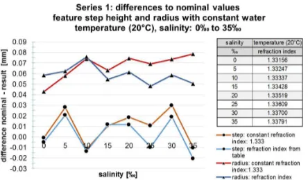
For the measurement series 1 (Figure 12) the salinity is increased in 5‰ steps up to 35‰, which reflects the average salinity of sea water. The water temperature is constant (20°C). Figure 12 illustrates the measurement results of a constant and a corrected refraction index. The deviations of the step height (reference: 3mm) to the uncorrected results are about 10µm up to 20µm. The measurement noise is in the range of 40µm.
Figure 12. Results of an underwater measurement with constant temperature and increasing salinity
The deviations from the circle radius (reference: 12mm) are 40 to 80µm higher. Possibly a part of this systematic deviations are caused by a non-perpendicular orientation of the measuring object to the laser beam. In this case the measuring points on the cylinder are not a circle anymore. But nevertheless the influence of the salinity can be observed. The deviations of the uncorrected measurements increase by increasing the salinity and show a minimum amount of 40µm. The measurement noise is in a range of 30µm.
For the measurement series 2 the temperature is increased in 2°C steps from 10°C to 30°C. The salinity is constant at 35‰ (Figure 13). The systematic deviations of circle measurement look similar to series 1 but the measurement noise is, with a range of 60 microns, higher than in series 1. It can be seen that the influence of temperature is not as high as the influence of salinity with respect to the change of the refraction index and the subsequent measurement results. The differences between the corrected the uncorrected measurements of the radius do not change during the increasing temperature.
Figure 13. Results of an underwater measurement with constant salinity (35‰) and increasing temperature
In conclusion it can be stated that these results show relative deviations that still may be subject to systematic uncertainties in the refractive indices which have not been measured absolutely but taken from previous publications. However, it can be seen that these corrections lead to better results with smaller noise or lower deviations to the reference values. In addition, these results are within our specified accuracy of 0.1 mm.
4. EVALUATION AND OUTLOOK
The demonstrator allows the acquisition of surface topographies of objects under water by using a simple multi-media approach. Thereby the measurement object is located in a water-filled aquarium and the demonstrator is positioned in front of it.
The results of the contour artefact measurements show clearly, that the measurement process works well under laboratory conditions. However, this simple multi-media approach is not adequate for practical application under real conditions. Therefore a flexible multi-media approach is necessary where the refraction index for water can be determined on site with high accuracy within a bundle adjustment (standard deviation of 0.00015; Maas, 2014).
During the project it has turned out that the tracking and positioning concept is improvable. For the positioning camera the optical distance through the medium water is about 1 m. Due to many floating particles in seawater the visibility to the object reference is reduced. In addition, the object reference has to be located in the field of view of the positioning camera, which reduces the flexibility of the measuring system. An object reference in the direct surrounding of the measuring point reduces the multi-media distance. And this, in turn, reduces the error propagation of the positioning uncertainties. Equally this method extends the working range of the measurement system. A new positioning concept could also simplify the camera concept, where the cameras of the stereo laser-profile system also measure the object reference. For the utilization of an underwater solution and diving trips, a camera housing has to be developed and manufactured.
5. APPENDIX
This project is funded by the German Federal Ministry of Economics and Technology in cooperation with the German Welding Society project funding number IGF 17.333N / DVS V4.005.
6. REFERENCES
References from Journals:
Bethmann, F., Luhmann, T., 2010. Least-squares matching with advanced geometric transformation models.
In: International Archives of Photogrammetry, Remote Sensing and Spatial Information Sciences, Vol. XXXVIII, Part 5 Commission V Symposium, Newcastle upon Tyne, UK, 2010, 86-91.
Ekkel, T., Meyer, A.M., Luhmann, T., Hastedt, H., Bethmann, F., 2013. Development of a stereo-laser profile-system for the optical inspection of welding seams. ISPRS Annals of Photogrammetry, Remote Sensing and Spatial Informations Sciences, Volume II-5/W2 (2013), S. 79/84.
Harvey, E. S.; Cappo, M.; Shortis, M. R.; Robson, S.; Buchanan, J. and Speare, P., 2003. The accuracy and precision of underwater measurements of length and maximum body depth of southern bluefin tuna (Thunnus maccoyii) with a stereo-video camera system. Fisheries Research, 63: 315-326.
Korduan, P., Förster, T., Obst, R., 2003. Unterwasser-Photogrammetrie zur 3D-Rekonstruktion des Schiffswracks "Darßer Kogge". Photogrammetrie Fernerkundung Geoinformation, Nr. 5, S. 373 – 381
Luhmann, T.; Bethmann, F.; Herd. B.; Ohm, J., 2008. Comparison and Verification of Optical 3-D Surface Measurement Systems. International Archives for Photogrammetry and Remote Sensing, Vol. 37, Part 5B, Beijing, pages 51-56.
Luhmann, T., 2009. Precision potential of photogrammetric 6 DOF pose estimation with single images, ISPRS Journal of Photogrammetry and Remote Sensing, Vol. 64/3
Maas, H.-G. 2014. Geometric Models of Multimedia Photogrammetry, Allgemeine Vermessungsnachrichten (AVN) 121 (2014) 3, pages 112-116.
Mulsow, C., 2010. A flexible multi-media bundle approach. International Archives Photogrammetry and Remote Sensing, Vol. 38/5, pages 472-477
Shortis, M. R.; Miller, S.; Harvey, E. S. and Robson, S., 2000. An analysis of the calibration stability and measurement accuracy of an underwater stereo-video system used for shellfish surveys. Geomatics Research Australasia, 73: 1-24.
Vilaca, J. L.; Fonseca, J.; Pinho, A. C.; 2006. Calibration Procedure for 3D Surface Measurements using Stereo Vision and Laser Stripe, Proc. RPD 2006
Quan, X., Fry, E.S, 1995. Empirical equation for the index of refraction of seawater, Applied Optics, Vol. 34 No.18, pages 3477-3480.
References from books:
Bass M. et al., 2009. Handbook of Optics, Third Edition Volume IV: Optical Properties of Materials, Nonlinear Optics, Quantum Optics, McGraw-Hill Professional, third edition, New York.
Luhmann, T.; Robson, S.; Kyle, S.; Boehm, J., 2014. Close-Range Photogrammetry. De Gruyter.
Meschede, D., 2008. Optik, Licht und Laser. 3. Auflage, Vieweg+Teubner, Wiesbaden, ISBN 978-3-8351-0143-2
References from other Literature:
Austin, R.W., Halikas, G., 1976. The index of refraction of seawater, SIO Ref. 76-1 (Scripps Institution of Oceanography, La olla, Calif.)
Hastedt, H., Luhmann, T., Raguse, K., 2005. Three-dimensional acquisition of high-dynamic processes with a single-camera system and stereo-beam splitting. In: Optical 3-D Measurement Techniques VII; Grün/Kahmen (Eds.)
Höhle, J., 1971. Zur Theorie und Praxis der Unterwasser-Photogrammetrie. Deutsche Geodätische Kommission, Reihe C, Nr. 163, Dissertationen, Bayerische Akademie der Wissenschaften in Kommission bei der C.H.Beck´schen Verlagsbuchhandlung München
Hildebrandt, M. et al., 2008. A practical underwater 3D-Laserscanner, In: Proceedings of the MTS/IEEE Conference on Oceans, Poles and Climate. OCEANS-08, Technological Challenges, September 15-18, Quebec, QC, Canada, IEEE
Klimentjew, D.; Hendrich, N.; Zhang, J.; 2010. Multi Sensor Fusion of Camera and 3D Laser Range Finder for Object Recognition, International Conference on Multisensor Fusion and Integration for Intelligent Systems, Sept. 5-7, University of Utah, Salt Lake City, IEEE, pages 236-241
Korduan, P. and Lämmel D., 2004. Low Cost-Stereo UW-Kamerasystems, Uni Rostock
Kotowski, R., 1987. Zur Berücksichtigung lichtbrechender Flächen im Strahlenbündel. Deutsche Geodätische Kommission, Reihe C, Nr. 330, Dissertationen, Bayerische Akademie der Wissenschaften in Kommission bei der C.H.Beck´schen Verlagsbuchhandlung München
Mc Ivor, A. M., 1999. Calibration of a Laser Stripe Profiler, Second International Conference on 3-D Digital Imaging and Modeling, IEEE, pages 92-98.
References from Websites:
AXIOS, 2015. Datasheet CamBar, AXIOS 3D Services GmbH, http://www.axios3d.de/Doc/datasheet/Datenblatt_CamBarB2C8 _EN.pdf, (03.03.2015)
Basler, 2015. Datasheet Basler Ace Camera, Basler AG,
http://www.baslerweb.com/en/products/area-scan-cameras/ace/aca2040-25gm, (09.03.2015)
Ross, B. J., 2014. COSC 3P98: Ray Tracing Basics. https://www.cosc.brocku.ca/Offerings/3P98/course/assignments /RayTracing.pdf, S. 17/19, (09.03.2015). Brock University, St. Catharines/Kanada 2014.