PSZ 19:16 (Pind. 1/97) UNIVERSITI TEKNOLOGI MALAYSIA
BORANG PENGESAHAN STATUS TESIS
♦JUDUL : MICROSOFT PROJECT 2003 AND PRIMAVERA PROJECT PLANNER IN HANDLING MULTIPLE CALENDARS
SESI PENGAJIAN : 2005 / 2006
Saya : ALVIN STANLEY A/L XAVIER
(HURUF BESAR)
mengaku membenarkan tesis (PSM/Sarjana/Doktor Falsafah)* ini disimpan di Perpustakaan Universiti Teknologi Malaysia dengan syarat-syarat kegunaan seperti berikut :
1. Hakmilik tesis adalah dibawah nama penulis melainkan penulisan sebagai projek bersama dan dibiayai oleh UTM, hakmiliknya adalah kepunyaan UTM.
2. Naskah salinan di dalam bentuk kertas atau mikro hanya boleh dibuat dengan kebenaran bertulis daripada penulis.
3. Perpustakaan Universiti Teknologi Malaysia dibenarkan membuat salinan untuk tujuan pengajian sahaja.
4. **Sila tandakan (9 )
SULIT (Mengandungi maklumat yang berdarjah keselamatan atau kepentingan Malaysia seperti yang termaktub di dalam AKTA RAHSIA RASMI 1972)
TERHAD (Mengandungi maklumat TERHAD yang telah ditentukan oleh organisasi/ badan di mana penyelidikan dijalankan)
TIDAK TERHAD
9
Disahkan oleh
_______________________________________ _______________________________ (TANDATANGAN PENULIS) (TANDATANGAN PENYELIA) Alamat Tetap :
18,SELASAR TEBING KINTA 2,
TAMAN MIRINDI, PN. PONSELVI JEEVARAGAGAM
31400 IPOH, PERAK. Nama Penyelia
Tarikh : 14 APRIL 2006 Tarikh : 14 APRIL 2006
CATATAN : * Potong yang tidak berkenaan.
** Jika tesis ini SULIT atau TERHAD, sila lampirkan surat daripada pihak berkuasa/organisasi berkenaan dengan menyatakan sekali sebab dan tempoh tesis ini perlu dikelaskan sebagai SULIT atau TERHAD.
I hereby declare that I have read this dissertation and found its content and form to meet acceptable presentation standards of scholarly work for the degree of
Bachelor of Engineering in Civil Engineering
Signature : _________________________________
Name of supervisor : Pn. Ponselvi Jeevaragagam
MICROSOFT PROJECT 2003 AND PRIMAVERA PROJECT PLANNER 3.0 IN HANDLING MULTIPLE CALENDARS
ALVIN STANLEY A/L XAVIER
This research report submitted in partial fulfillment of the requirements for the award of the degree of
Bachelor of Civil Engineering
Faculty of Civil Engineering
Universiti Technology of Malaysia
MICROSOFT PROJECT 2003 AND PRIMAVERA PROJECT PLANNER 3.0 IN HANDLING MULTIPLE CALENDARS
ALVIN STANLEY A/L XAVIER
Laporan kajian ini
dikemukakan sebagai memenuhi
syarat penganugerahan Ijazah Sarjana Muda Kejuruteraan Awam
Fakulti Kejuruteraan Awam Universiti Teknologi Malaysia
iii
DECLARATION
I declare that this entire dissertation is the result of my own research except for commonly understood ideas and others which I have clarified their sources. The dissertation has not been previously submitted and is not being concurrently submitted for any other degree or qualification.
Signature : ________________________
Name : ALVIN STANLEY s/o XAVIER
v
ACKNOWLEDGEMENT
I would like to express my sincere gratitude and thanks to my supervisor, Pn Ponselvi Jeevaragagam for her generous guidance, cooperation and advices from time to time throughout the duration of this dissertation. Her valuable knowledge and support is greatly appreciated.
I would also like to thank Mr. Augustine Michael, shift engineer at Angkasa Consulting Services Sdn. Bhd for his help on attaining the case-study data from Sg. Kinta Dam Project. His assistance in attaining numerous types of data and information widen my knowledge, not only about my research, but also the construction of the dam.
I also take this opportunity to thank Venga, Kuga, Shalom, Logen, Param, Giri, Mani, Puther, Sivadass and all my housemates for making my stay at UTM a memorable one.
Abstract
Calendars in construction project show the working and non-working days of a certain resource or a group of labors to a certain task assigned to them. Many
vii
Abstrak
Kalendar dalam sesuatu projek pembinaan berfungsi untuk memaparkan hari bekerja dan tidak bekerja bagi sesuatu sumber atau sekumpulan pekerja yang telah
dipertanggungjawab dengan sesuatu projek. Terdapat banyak projek pembinaan yang menggunakan lebih dari satu kalendar untuk menunjuk keadaan sesuatu projek seperti ciri-ciri atau sifat sesuatu kerja, kemudahan memperolehi sumber, keadaan cuaca dan sebagainya. Pakej perisian pengurusan projek seperti Microsoft Project 2003 dan Primavera Project Planner 3.0 menawarkan pelbagai kalendar dalam pakej perisisannya. Kajian ini dijalankan untuk mengenalpasti miskalkulasi yang terhasil dari pakej perisisan yang mempunyai pelbagai kalendar. Kesemua empat jenis hubungan dengan faktor kelengahan negatif, sifar dan positif dianalisis secara manual serta mengunakan kedua-dua pakej perisian. Hasil analisis menunjukkan kedua-dua perisisan menghasilkan kesalahan dalam semua jenis hubungan dengan kelengahan negatif dan sifar bagi Start-Finish dalam keadaan ‘special case’. Terdapat beberapa kesalahan lain yang dihasilkan oleh Microsoft Project 2003 dalam kes Start-Start dan Finish-Start dengan faktor kelengahan positif dan negatif, serta hubungan antara Finish-Finish dan Start-Finish dengan faktor kelengahan sifar dan negatif. Kajian tambahan turut dijalankan mengenai kelebihan dan kekurangan kedua-dua pakej perisisan Microsoft Project dan Primavera dibawah skop fungsi calendar, aktiviti input ID, WBS dan aktiviti rangkaian. Kajian tambahan ini menunjukkan bahawa Microsoft Project memiliki sistem calendar yang lebih baik, memiliki fungsi input aktiviti yang mudah dan WBS yang lebih tersusun. Kajian ini mencadangkan supaya mengelak menggunakan hubungan dengan jenis kelengahan seperti yang telah dibincangakan supaya dapat mengasilkan putput yang lebih jitu apabila menggunakan kalendar pelbagai fungsi melalui kedua-dua pakej perisian
TABLE OF CONTENTS
CHAPTER TOPIC PAGE
THESIS STATUS DECLARATION SUPERVISOR DECLARATION
TITLE i
TAJUK ii
DECLARATION iii
DEDICATION iv
ACKNOWLEDGEMENT v
ABSTRACT vi
ABSTRAK vii
TABLE OF CONTENTS viii
LIST OF FIGURES xii
GENERAL NOTATIONS xiv
LIST OF APPENDICES xv
CHAPTER 1 INTRODUCTION 1
1.1 Background 1
1.2 Research Objectives 2
1.3 Research Scope 3
ix
CHAPTER 2 LITERATURE REVIEW 4
2.1 Introduction to Scheduling 4
2.2 Significance of Scheduling for the Participants 5
2.3 Scheduling Techniques 5
2.3.2 .Precedence Diagram Method (PDM) 9
2.4 Drawback to CPM and PDM 10
2.5 Introduction to the Multiple Calendars in CPM 11
3.3.1. Literature review 25
4.2 Comparison between Single and Multiple Calendars 29
4.3 Multiple Calendars Manual Analysis 31
4.4 Multiple Calendars Analysis in Microsoft Project and P3 33
4.4.1. Special Case Analysis in Project and P3 33
xi
REFERENCES 66
LIST OF FIGURES
4.4 Finish-Start (FS) with lag negative (Special case) 36
4.5 Finish-Finish (FF) with negative lags (Special case) 37
4.6 Start-Finish (SF) with negative lags (Special case) 38
4.7 Start-Start (SS) with negative lags (Special case) 39
4.8 Start-Finish (SF) with zero lag (Special Case). 40
4.9 Finish-Finish (FF) with zero lags (Project) 43
4.10 Finish-Finish (FF) with negative lag (Project) 44
4.11 Start-Start (SS) with positive lags (Project) 45
4.12 Start-Start (SS) with negative lags (Project) 46
4.13 Finish-Start (FS) with positive lags (Project) 47
xiii
4.19 Necking for non-working days in P3 54
4.20 WBS Code Definition in Microsoft Project 56
4.21 WBS Hierarchy Display in Microsoft Project 56
4.22 Activity Code Increment Option in P3. 58
4.23a WBS hierarchy in P3 58
4.23b WBS hierarchy in P3 and Gantt chart 59
GENERAL NOTATIONS
Symbols
AOA - Arrow on arrow
AON - Arrow on node
d - Duration
d1 - Modified Duration
EF - Early Finish
ES - Early Start
FF - Finish-to-Finish
FS - Finish-to-Start
EFT - Early Finish Time
EST - Early Start Time
LF - Late Finish
LS - Late Start
LFT - Late Finish Time
LST - Late Start Time
SF - Start-to-Finish
SS - Start-to-Start
xv
LIST OF APPENDICES
APPENDIX TITLE PAGE
A Case Study Schedules in Microsoft Project 68
2003 Format
B Case Study Schedules in Primavera Project 72
Chapter 1
INTRODUCTION
1.1. Background
The use of information technology is common in the construction industry. A wide range of data can be stored, managed, and manipulated using information technology tools. In the case of scheduling, Microsoft Project and Primavera Project Planner are a few of leading software being used in current date. Microsoft Project is well known as easy-to-use software while Primavera is high-end software.
Scheduling for a single calendar using this software is rather easy and common. But, there are chances for a single construction project to have multiple calendars. The occurrence of multiple calendars can be regarded to the work properties, weather condition, resource available and other reasons (Lock.2000). In a planner of multiple calendars, each calendar has a unique working day of its own. For example, a construction planner can have two calendars, one for three days working days and another for seven days working days.
2
assume without clear knowledge that the data generated by the software are correct. It has, however has been noticed that Microsoft Project and Primavera (3P) generates incorrect data and inconsistent results under certain conditions dealing with multiple calendars(Kyunghwan Kim and Jesús M. de la Garza, 2005).
It is well known that Microsoft Project is a user-friendly software and P3, in the other hand, very sophisticated software. As an additional objective to this research, a few functions in both software are been analyzed for comparison purpose. Conclusions are made within the scope of aspects analyzed and the overall comparison of both software packages is ignored.
1.2. Research Objectives
The objective of this study would be:
o To determine relationship types with lag conditions in which miscalculations
occur in Microsoft Project 2003 and Primavera Project Planner 3.0 dealing with multiple calendars.
o To compare Microsoft Project and Primavera Project Planner in the aspects of
1.3. Research Scope
Primavera and Microsoft Project are two leading software in project management. Each has unique features to generate project data on project plan, organize resources, assign responsibility, and follow up during construction. In this paper, however, the scope is limited only certain functions in both Project and P3. The scope of functions is listed as below.
• Multiple calendars and activity relationship
• Calendars
• Activity input and Work Breakdown Structure
• Activity linking
It has been noticed that newer versions of these software are in market every year. The software used in this paper is Microsoft Project 2003 and Primavera Project Planner version 3.0.
1.5. Importance of the Study
This study serves the significance for academicals and practical purpose. In terms of academic, this paper could help the users of the project management software packages to understand about the multiple-calendars-based scheduling and it’s the conditions of miscalculations.
Chapter 2
LITERATURE REVIEW
2.1. Introduction to Scheduling
Scheduling provides an important role in a construction project. Where there is no plan, where the disposal of time is surrendered merely to the chance of incidence, chaos will soon reign(Victor Hugo, 1802-1885). Without a plan, there is no way to schedule the required work, no way to track progress, and no way of deciding on corrective action when unexpected events occur (Stella and Glavinich, 1994).
2.2. Significance of Scheduling for the Participants
The need for proper planning and scheduling of construction projects is crucial for all parties involved. The major parties involved in a construction project are the owner, consultants and the contractors.
The owner uses schedules and plans in the aspect of monitoring. Indirectly, he gains control over the project. Another importance of scheduling to the owners is to predict the financial needs of the project.
The scheduling significance for the consultants is in the form of activities like research, design, and estimation, and documents preparation.
Scheduling is a crucial to the contractors. Scheduling is used as a tool in determining the quantity of labor, the types and quantity of plants, the time duration of an activity, the time and duration for material supplies and to estimate financial flow and need. By proper planning and scheduling, contractors increase the possibility that a project will be completed within budget, will be within the time constraints, and will have better quality, and they can reduce the chances of chaos breaking out.
2.3. Scheduling Techniques
6
industrial engineering applications, CPM has gone through an evolution over the last 40 years, from arrow diagrams, the program evaluation and review technique, and precedence diagrams to the current sophisticated commercial software used today.It is important to note that the development of CPM took time and a different approach to arrive at what it is used today.
The basic of all network scheduling is the Activity on Node (AON) and Activity on Arrow (AOA). In AOA networks, the traditional CPM is used and in AON networks, the CPM is slightly modified and referred as Precedence Diagram Method (PDM). Other famous network scheduling method is Program Evaluation and Review Technique. This paper is focused merely on CPM and PDM methods.
2.3.1. Critical Path Method (CPM)
The CPM is a systematic scheduling method for AOA network. The CPM involves in major four steps
• A forward pass to determine activities early-start times. (EST)
• A backward pass to determine activities late-finish times. (LFT)
• Float calculations
• Identifying critical activities
2.3.1.1. Forward Pass
Each of the nodes in the network, in fact, a point at which some activities end (head arrow coming into the node) and some other activity starts on the same node.
All successor activities can only start after the latest predecessor is finished. Therefore, for the forward pass to determine the early-start (ES) time of an activity, the head arrow coming into the start node of an activity is observed. Then, the activity ES time is set as the latest finish time of all. The early finish time is calculated as the formula 2.1:
Early-Finish (EF) = Early-Start (ES) + d (2.1)
where d indicates the duration of the activity.
It is must to be taken into consideration the largest EF value of the predecessor activities is used to calculate the ES of successor’s activity if the successor has multiple predecessors, and all other values are not used.
2.3.1.2. Backward Pass
The backward pass determines the late-finish (LF) times of activities by proceeding backward from the end node to the starting node of a AOA network. For a backward pass to determine the late-finish times of the activities, the successors (tail arrow) going out of the node is looked upon and their smallest late-start (LS) value is evaluated and this value is used as the LF time of the predecessors. LS times can be calculated as formula 2.2:
8
The LS time of the last node in a backward pass is necessary to be checked to ensure the correctness of the calculation. The checking formula is as given below (formula 2.3):
Late-start (LS) = Late-finish (LF) - d = 0 (2.3)
2.3.1.3. Float Calculation
Once forward-pass and backward-pass calculations are complete, it is possible to analyze the activity times and find the conclusions. One important aspect is Total-Float (TF) calculations, which determine the flexibility of an activity to be delayed. There are two ways of scheduling an activity using its activity times. One way is to schedule its as early as possible (using its ES time). The other way is as late as possible (using its LS time). The activity float can be represented by the following relationships:
Total Float (TF) = Total Slack (2.4) = LF - EF
= LF - ES
Subtracting the activity duration, the total floats becomes:
Another type of float often used in network analysis is the Free Float, which can be calculated as:
Free Float = ES (of succeeding activity) – (2.6) EF (of activity in question)
The free float defines the amount of time that an activity can be delayed without taking float away from any activity. With free float available for an activity, a project manager knows that the float can be used without changes in the status of any non-critical activity to become critical.
2.3.1.4. Critical Activities
The total float values of activities are very useful for realistic scheduling of the activities and in responding to many changes that occur on site. Activities with zero floats mean that they have to be constructed right at their times, without delays. These activities, as such, are considered critical. They deserve the special consideration of the project manager because any delay in critical activities causes a delay in the project duration.
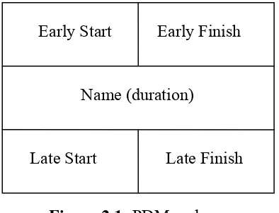
2.3.2. Precedence Diagram Method (PDM)
10
Early Start Early Finish
Name (duration)
Late Start Late Finish
Figure 2.1: PDM node
2.4. Drawback to CPM and PDM
The CPM and PDM analyses for network scheduling offers vital information that can lead the project to its accomplishment. Both methods, however, has some weakness that require special attention from the project manager. These drawbacks are as follow:
• The forward and backward pass calculations do not incorporate resources into their formulation. Dealing with limited resources has to be done separately after analysis.
• Since CPM and PDM formulations deal mainly with activities durations, not
resources, most often they result in large fluctuations in the total resources, from one day to another. Special resource-leveling effort has to be done, therefore reduce the hiring and firing of resources.
• The formulation of CPM and PDM methods do not incorporate to constrain project duration.
• Since CPM and PDM methods deal mainly with activities durations, they do
• The basic assumptions in CPM and PDM formulations are that activity duration are deterministic. In reality, however, activity durations take certain probabilistic distribution that reflect the effect of on project condition on resource productivity and the level of uncertainty involved in the project.
• With CPM and PDM analysis determining the start times of activities, it is
possible to convert these start times to calendar days and accordingly identify the time of the year in which each activity is planned to be constructed. Based on that, it is possible to modify activity duration and cost to reflect the impact productivity factors such as weather conditions. Accordingly, total project duration becomes longer but more closely reflects actual construction conditions.
d1 (modified duration) = d (original duration)/productivity
factor (2.7)
c1 (modified cost) = d (original cost)/productivity factor (2.8)
2.5. Introduction to the Multiple Calendars in CPM
12
It is common to have multiple calendars according to task properties, weather conditions, resource availabilities, and other reasons in a construction project (Lock 2000). At times, a single resource, for an example, an excavator is assigned to more than one project site in the same week, and its working days in the destined project site is just three days in a week. In these situations, it is important to assign a single calendar specifically for this task and the follow-ups uses a different calendar concerning the task type. Multiple calendars have unique working pattern per week. For example, a construction schedule can have three project calendars: one for a 3 day work week (Monday, Tuesday, and Wednesday), another for a 5 day work week (Monday through Friday) and the other for a 7 day work week (continuous working days). Then, any activity of the schedule can use one of the calendars based on the activity condition.
2.5.1. Basic Rules for Multiple Calendars
CPM rules are commonly used in single calendar based scheduling. However, consideration must be given when dealing with multiple calendars. The approach is slightly different in each case of relationship type and lag amount, but a set of basic rules as described below are applied to most cases.
Basic rules in multiple calendars (Kyunghwan K and Jesús M. de la Garza, 2005).
1. The relationship lag time belongs to the predecessor’s calendar in both forward and backward passes. If the lag time property does not correspond to the predecessor’s calendar, the lag can be replaced with an activity that has a different calendar to correctly represent the lag property.
2. Activity split is not allowed, except for the period of nonworking days. An activity must stop on the non-working days and continue on the next available working day.
3. The relationship lag time indicates the minimum time interval that must exist between two activities in both forward and backward passes.
4. In forward pass, if the early time (EST or EFT) of the successor calculated directly from the predecessor is a nonworking day, the early time should be postponed to the next available working date of the successor’s calendar. Similarly, in backward pass, if the late time (LST or LFT) of the predecessor calculated directly from the successor is a nonworking day, the late time should be advanced to the previous available working date of the predecessor’s calendar. This is done to assure the minimum time interval condition
5. The scheduling unit is 1 day and every activity starts at the beginning of the day and finishes at the end of the day.
6. The beginning of a day is identical to the end of the previous day. After applying the lag time, the beginning time is applied to find the start time of an activity and the end time is applied to find the finish time of an activity
14
available on the same date. The difference between the beginning and the end of the day is also 1 day.
8. If an activity has multiple successors with the same relationship type, but with different lag time values, the early time of a successor with a longer lag time must be greater than or equal to the early time with a shorter lag time. The following equation shows this early time property with different lag times from on predecessor:
ET n, i ≤ ET n+1,j (2.9)
Where n = lag time (integer); and ET n,, j = ET (EST or EFT) of activity i with
n lag.
When an activity is involved with more than two calendars through related activities, the early time of an activity in the forward pass is the maximum early time among all possible early times calculated from predecessors. Each possible early time is calculated based on two calendars: one for the predecessor and the other for the successor. The same condition happens for the backward pass. The late time of an activity in the backward pass is the minimum late time among all possible late times calculated from successors. Each possible late time is calculated based on two calendars.
2.5.2. Forward Pass
2.5.2.1 Finish-to-Start and Start-to-Start
In a finish-to-start (FS) and start-to-start (SS) with zero lag, the successor activity can start immediately after (for FS: 0) or start at the same time (for SS:0) or later than the predecessor activity finishes. The earliest possible start time of the successor is the next day (for FS: 0) and the same day (for SS: 0) of the predecessor’s EFT and EST respectively.
In a FS and SS with positive lag, the successor can start at the lag time after or later than the predecessor finishes. The earliest possible start time of the successor is the next day of the predecessor’s EFT (for FS: +) and EST (for SS: +) plus the amount of lag time counted by working days on the predecessor’s calendar.
Similarly, in a FS and SS with negative lag, the successor can start at the lag time before or later than the predecessor finishes. The earliest possible start time of the successor is the next day of the predecessor’s EFT (for FS: -) and EST (for SS: -) less the amount of lag time counted by working days on the predecessor’s calendar. In other words, the successor can start when the remaining duration of the predecessor on the predecessor’s calendar is at most the lag time.
2.5.2.2. Start-to-Finish and Finish-to-Finish
16
In a SF and FF with positive lag, the successor can finish at the lag time after or later than the predecessor starts (for SF) and finishes (for FF). The earliest possible finish time of the successor is the previous day (for SF) and on the same day (for FF) of the predecessor’s EST plus (for SF) or predecessor’s EFT minus (for FF) the amount of the lag time counted by working days on the predecessor’s calendar.
With a SF and FF and negative lag, the successor can finish at the lag time before or later than the predecessor starts (for SF) or finishes (for FF). The earliest possible finish time of the successor is the previous (for SF) or on the day (for FF) of the predecessor’s EST and EFT less the amount of lag time counted by working days on the predecessor’s calendar respectively.
2.5.3. Backward Pass
The backward pass begins after the forward pass is completed for all activities. In the backward pass, the late times of each activity are calculated based on the late times of the successors. As mentioned in the basic rules, the relationship lag time is also the minimum time interval that must exist between two activities in the backward passes. The backward pass with multiple calendars is similar to that with continuous working days, but it has additional features to handle nonworking days.
2.5.3.1. Finish-to-Start and Start-to-Start
possible finish time (for FS) or start time (for SS) of the predecessor is the previous day of (for FS) and same as (for SS) the successor’s LST.
In a FS and SS with positive lag, the successor can start at the lag time after or later than the predecessor finishes (for FS) and starts (for SS). With this property, the latest possible finish time (for FS) and start time (for SS) of the predecessor is the previous day of (for FS) and the same day as (for SS) of the successor’s LST less the amount of the lag time counted by working days on the predecessor’s calendar.
In a FS and SS with negative lag, the successor can start at the lag time before or later than the predecessor finishes (for FS) and starts (for SS). With this property, the latest possible finish time (for FS) and start (for SS) of the predecessor is the previous day of (for FS) or the same day as (for SS) the successor’s LST plus the amount of the lag time counted by working days on the predecessor’s calendar.
2.5.3.2. Start-to-Finish and Finish-to-Finish
In a SFand zero lag, the successor activity can finish on the previous day or later than the predecessor activity starts whether the schedule is based on early times or late times. Because the predecessor could start the next day of the successor’s finish, special care is required in the backward pass with SF:0, especially when nonworking days are involved. The latest possible start time of the predecessor is the next day of the successor’s LFT or, if it is a nonworking day, the next available working day.
18
early times or late times. With this property, the latest possible finish time of the predecessor is the same time of the successor’s LFT.
In a SF and FF with positive lag, the successor can finish at the lag time after or later than the predecessor starts (for SF) and finishes (for FF). With this property, the latest possible start time of the predecessor is the next day of (for SF) or the same days as (for FF) the successor’s LFT less the amount of the lag time counted by working days on the predecessor’s calendar.
In a SF and FF with negative lag, the successor can finish at the lag time before or later than the predecessor starts (for SF) or finishes (for FF). With this property, the latest possible start time of the predecessor is the next day of (for SF) or the same day as (for FF) the successor’s LFT plus the amount of lag time counted by working days on the predecessor’s calendar.
2.6. Project Management Software.
The software that are analyzed in this paper are Microsoft Project version 2003 and Primavera Project Planner (P3) version 3.0. Microsoft Project is popular easy-to-use project management software, and P3 is high-end software for project management. Both software systems allowputting together a project plan, organizing resources, and assigning responsibilities and adjustment during construction.
availability and fine-tuning the plan to satisfy time and budget constraints or to accommodate changes. It have the features to prepare professional-looking reports to explain the project to owners, top management, supervisors, workers, and the public.
Once work begins on the project, these project management software can be used to track progress and analyze the evolving actual schedule to see if it looks like if the project will finished in time and within budget. These software allocates the schedule to be revised and accommodate changes to unforeseen circumstances. This improves communicate within team members about the changes in the schedule and implore feedback about their progress. It also allows posting automatically updated progress reports on an Internet website or a company intranet (Nancy Stevenson, 2005).
Other software packages include Open Plan, Panorama Trackstar, Macproject, Artemis, Baronet and many more (Wager,1991). Many of these software have adapted user friendly Windows-based.
2.6.1. Microsoft Project 2003
The history of Microsoft Project tracked back in the 1990, when its first version of Microsoft Project 1.0 was introduced. Since then, it has become one of the leading software among others. One of its major factors for its popularity is because it is a built- into Microsoft Office packages. Newer versions are followed up along with Microsoft Office progression. Microsoft Project 2003 is the seventh version.
20
also easy-friendly software. The Project Guide, similar to other guides found in other Microsoft Office products wizard, provide help to the users throughout the entire life of the project, from data input to final report generation.
It also provide data conversion to other Microsoft Office products, such as Microsoft Excel2003 , Microsoft Outlook 2003, Project Web Access 2003 or any MAPI (MAPI, Messaging Application Programming Interface, which is the standard programming interface proposed and supported by Microsoft for accessing electronic messaging.) compliant e-mail system. Sending project files through e-mail improves project communication and increases the speed of schedule reviews. Microsoft Project has special features of graphical import. Audio, video, or animation files can be insert file into a Project file. This improves the visualization of the real time project.
Microsoft Project 2003 has typical functions of ordinary project management software plus some extra features. It enables detailed closeable work breakdown structure, fourteen types of result-viewing results, that includes, Gantt charts, calendars, network diagrams, resources graphs and many more with printable results. It also enables the setting of wartimes. Other features include resource leveling and contouring, network analysis and cash flow analysis.
2.6.2. Primavera Project Planner 3.0 (P3)
The latest version of 3P is Primavera Project Planner version 3.3, but in the case of construction industry, version 3.0 is commonly used. Primavera is the most popular scheduling in construction industry (Jimmie, 1998). Planning in 3P has become so common that it is must in some project contract submission in Malaysia.
Excluding the common features, such as scheduling, resource management and scheduling, cost estimation, cash flow analysis, P3 also offers extra features. The features in 3P include 31 task calendars and 2340 resource calendars. It also manages 100,000 activities with unlimited resource and target project. It has 20 levels in Work-Breakdown Structure, 24 activity codes, 10 project codes, 19 level of sorting and more than 150 standard reports (www.pmbelgie.be/body_index.html).
P3 can manage mega projects. In Malaysia alone, mega projects such as Development Projects of KLCC (Kuala Lumpur City Centre) and Putrajaya was scheduled using P3. P3can be used in all conditions, from project involves multiple organization to critical projects with limited resource.
Chapter 3
METHODOLOGY
3.1. Overview
This chapter explains about the method used in carrying out the study in order to achieve its objectives. To show the contradictions in the both software handling multiple calendars, simple PDM networks are created and each PDM network is analyzed using both software. A case study has been enclosed to serve the secondary objective of comparison of certain functions in both software. Other sources of information are from textbooks, journals, conference papers, and from internet.
3.2. The Case Study
Contract Title : Greater Ipoh Water Supply Scheme II
Construction of Sg. Kinta Dam and Associated Works
Employer : Lembaga Air Perak
Project Manager : Metropolitan Utilities Corporation Sdn. Bhd.
Consultants : Angkasa Consulting Services Sdn. Bhd. Gutteridge, Haskins & Davey Pty. Ltd.
Contractor :Seribong-Konbina-Hazama Consortium
Contract Sum : RM 149,500,000.00
Contract Period : 34 months
Contract
Commencement Date : 27 January 2003
Time Elapsed : 32 months
Original
Completion Date : 27 November 2005
Revised Completion Date
24
3.3. Research Methodology
The research will go through several phases as follow:-
i. Literature review ii. Data collection
iii. Analysis and example of calculation iv. Conclusions
3.3.1 Literature review
Literature review is also known as the secondary data that we get before the study is being carried out. It is for getting a better understanding of the study before it is started. Sources for the literature review are from the primary and secondary sources like textbook, journals, conference papers, and internet. The study of the both software in detail is carried out from its user guides, consultations with lectures and seminars.
3.3.2 Data collection
Data collection for this paper is the schedules of the case study (refer Appendix 1 and 2). Expected data to be gained are as below:
• Master program schedule
3.3.3. Analyze
The analyzing of data is done to fulfill the objectives and the serve the hypothesis. It is divided into three sections. To serve the first objective, literature review is done to improve the knowledge in multiple calendars conditions. A simple analysis in Project is done to determine the difference between continuous working day calendar and multiple calendars. The results are shown in section 4.2. In the second section, simple PDM are formed to evaluate the contradiction in the software used in terms of handling multiple calendars. The simple PDM networks are formed to ease the level of understanding of the software users. In the third section, the case study data is used to evaluate the Project and 3P for comparison. The elements that are evaluated are calendars, activity ID input, Work-Breakdown Structure (WBS), and activity linking. This serves as a secondary objective to the research to conclude the better software in the scope of the elements mentioned.
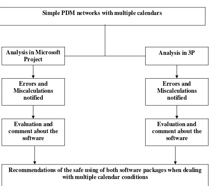
For the first objective of determining the conditions of the miscalculations in both software packages, below are the steps (Figure 3.1).
• Simple PDM networks are created with two calendars. All cases of ‘start-finish’, ‘start-start’, ‘finish-start’, ‘finish-finish’ with positive lags, zero lag and negative lags are taken into consideration in terms of the basic rules of multiple calendars as described in Literature Review
• The PDM networks are analyzed with 3P and Microsoft Project.
26
3.3.4. Flowchart
Analysis in Microsoft Project
Analysis in 3P Simple PDM networks with multiple calendars
Errors and
Recommendations of the safe using of both software packages when dealing with multiple calendar conditions
3.3.5 Conclusion
Chapter 4
ANALYSIS AND RESULTS
4.1. Introduction
In this chapter, the analyses of objectives are discussed. The objective of this research is to determine relationship types with lag conditions in which miscalculations occur in Microsoft Project 2003 and Primavera Project Planner 3.0 dealing with multiple calendars. The second objective is to compare Microsoft Project and Primavera Project Planner in the aspects of calendars, activity input, WBS, and link conflicts using real-time case-study project schedule data.
The literature review of this research is to increase user-knowledge on the concepts of multiple calendars in a network analysis. Various source of information are been collected to conduct the research. The targeted information is on the set of basic rules to perform a network analysis on multiple calendars. The comparison of continuous working days calendar and multiple calendars are analyzed in section 4.2 to show the difference between them.
one-to-one relationship for two activities PDM are created with all relation types and lag conditions. Each relation types and lag conditions are analyzed separately with manual analysis, 3P, and Project. Since the analysis is more focused on the relationship among two activities with different calendars, the whole network analysis is ignored. The results of these analyses are also shown in the form of template charts to ease the understanding. The results are discussed in section 4.3.
To serve the second objective, case-study schedules from the Kinta Dam Project are gained. The elements of comparison are calendars, relationships and activity, and project status tracking. The results are discussed in section 4.4.
4.2. Comparison between Single and Multiple Calendars.
A continuous calendar is a single calendar used to schedule the entire activities in a project, whereby multiple calendars are the usage of more than 1 calendar for scheduling in a project.
For comparison purpose, a simple FS: 0 for all activities is created and analyzed in Project. The original schedule is assigned to a single calendar (continuous calendar). It is then modified to a multiple calendar condition with a standard calendar that has 5 working days and additional calendars that have 3 and 5 working days. Figure 4.1 and 4.2 shows the results.
30
multiple calendars condition Other than that, the critical path and the float flow do not have a continuous pattern (Daniels 2003). Scheduling with a single calendar will produce total float patterns which either will be equal or gradually increase throughout the backward pass (Figure 4.1). But in multiple calendars condition, the total float patterns vary because of the calendar conditions.
It is therefore can be concluded that conventional CPM concepts in terms of Total Float calculations.
.
Figure 4.1: Continuous working days schedule.
Total float patterns are equal or gradually increase throughout the backward pass
1 day delay in Activity B causes 3 days delay for Activity C in multiple calendars condition
The total float patterns vary because of the calendar conditions
Figure 4.2: Multiple calendar scheduling.
4.3. Multiple Calendars Manual Analysis using PDM
The analysis are done for all Finish-Start (FS), Finish-Finish (FF), Start-Finish (SF) and Start-Start (SS) relation types with zero, positive and negative lags. All manual analysis is shown in template charts. The PDM’s nodes are consisting of Activity ID, Calendar ID, and Duration ID.
32
The main focus of the manual analysis is to make adjustment to the activity if it falls on the non-working day. The activity then must be taken forward or backward to the available working day. The consideration of calendar’s working and non-working days must be taken in account. All relationship types are analyzed with two calendars, which is sufficient to reflect a real time project that has two calendars or more. When an activity is involved with more than two calendars through related activities, the early time of an activity in the forward pass is the maximum early time among all possible early times calculated from predecessors. Each possible early time is calculated based on two calendars: one for the predecessor and the other for the successor. The same condition happens for the backward pass. The late time of an activity in the backward pass is the minimum late time among all possible late times calculated from successors. Each possible late time is calculated based on two calendars.
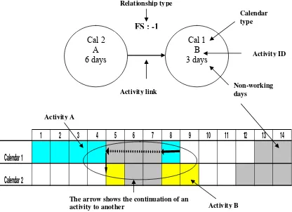
The arrow shows the continuation of an activity to another
Activity ID
Activity B
4.4. Multiple Calendars Analysis in Microsoft Project and P3
The template charts for all relationship types and lag conditions are analyzed and shown. The data of these charts are directly inputted in Project and 3P. The analysis is done for both forward and backward pass. Each following result’s figure is shown in template charts, Project and P3 forms. This is done for easy comparison of differences and error generation by the software.
4.4.1. Special Case Analysis in Project and P3
When dealing with multiple calendars in Project and 3P, it is been seen that both software generates different output in certain special cases. These special cases occurs when if the lag time is negative for all relationship types and if the earliest possible time of the successor after applying the lag time is the beginning of the next day of a nonworking day on the predecessor’s calendar. Presumably, no additional consideration is given to this special case without taking into account possible earlier times hidden by the nonworking days of the predecessor’s calendar. Both software packages are known to keep minimum lag time between two activities, but it does not take account of possible earlier finishing times to finish the project earlier by utilizing those hidden working days of the other calendar.
34
any of these conditions, special consideration should be taken to determine the EST for Activity B. While calendar one has only one day (day 8) to fulfill the condition, calendar two days (day 8 and day 4) with the relationship condition. The earliest time among them for Activity B would be is day 4. The output generated by both Project and P3 are the same and it is day 8, which could not be earliest EST to satisfy the condition.
Figure 4.5 shows a similar example for the Finish-Finish (FF) with negative one lag time. This figure however has three possible EST for Activity B; day 8, day 5 and day 4. The earliest EST for Activity B would be day 4. The output generation of Project and P3 is day 5, which still can be accepted as an EST for Activity B. But since day 4 is still accounted as the earliest EST for Activity B, preferably, day 4 should be chosen. Figure 4.6 and 4.7 are examples for Start-Finish and Start-Start with negative lags relationship, respectively.
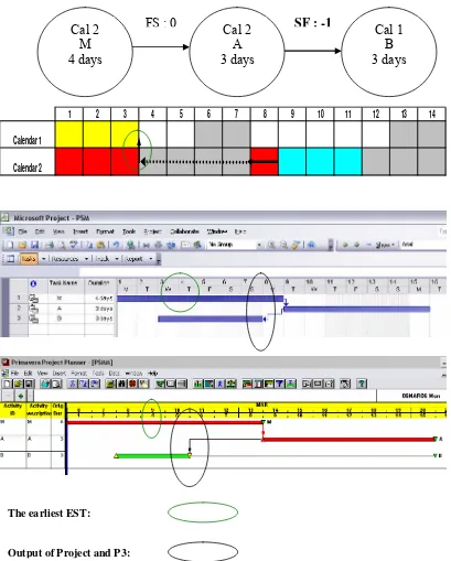
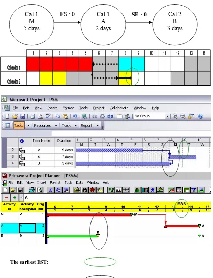
Another type of relationship that has a mistaken conception output in Project and Primavera is the Start-Start relation with zero lag. Unlike other relationship types of zero lags, the earliest possible finish time of the successor in SF: 0 is the previous day of the predecessor’s time as in negative lags. Thus, the same treatment for the negative lags should be applied to SF: 0. As shown in Figure 4.8, Activity A starts on day 8, after Activity M that has the Finish-Start with zero relationship. The successor, Activity B with Start-Finish (SF) relationship can finish at the end of day 7. Since end of day 7 is the same as the beginning of day 8, which is the next day of a non-working day on the predecessor’s calendar, the same method applied to the negative lag needs to be applied as shown on the bar chart. So, as Activity A will start at day 5, the successor, Activity B, must not finish earlier than end of day 5.
36
Cal 2 A 6 days
Cal 1 B 3 days
FS : -1
1 2 3 4 5 6 7 8 9 10 11 12 13 14
Calendar 1
Calendar 2
Project and P3 produce output of EST of day 9
Output of Project and P3: The earliest EST:
Cal 2 A 4 days
Cal 1 B 3 days
FF : -1
1 2 3 4 5 6 7 8 9 10 11 12 13 14
Calendar 1
Calendar 2
Output of Project and P3: The earliest EST:
38
1 2 3 4 5 6 7 8 9 10 11 12 13 14
Calendar 1
Calendar 2
Cal 2 A 3 days
Cal 1 B 3 days
SF : -1
Cal 2 M 4 days
FS : 0
Output of Project and P3: The earliest EST:
Figure 4.7: Start-Start (SS) with negative lags (Special Case). Cal 1
A 2 days
Cal 2 B 2 days
SS: -1
FS: 0 Cal 1
M 4 days
1 2 3 4 5 6 7 8 9 10 11 12 13 14
Calendar 1
Calendar 2
40
1 2 3 4 5 6 7 8 9 10 11 12 13 14
Calendar 1
Calendar 2
Cal 1 A 2 days
Cal 2 B 3 days
SF : 0
Cal 1 M 5 days
FS : 0
Output of Project and P3: The earliest EST:
4.4.2. Additional Errors in Project
Project generates several incorrect outputs in conditions when dealing with multiple calendars situations apart from the special cases as mentioned in section 4.3.2. Below are a few cases analyzed in Project.
In Figure 4.9, the template chart shows a FF: 0 relationships between two activities with two calendars. From the bar chart, it is noted that predecessor (Activity A) finishes on day 5, next day to a non-working day. The successor (Activity B) could not finish on day 4 to fulfill the relationship given. This is because the end of day 4 is identical to the beginning of day 5, which happen to be a non-working day. Therefore, the earliest EFT for Activity B would be on day eight and no earlier times. (Refer 2.5.1, Rule 6).
The output of Project in Figure 4.9 is end of day 5, which happen to be a non-working day. Figure 4.10 for FF: -1 lag time supports the matter. In this case, it clearly shows the violation of Rule 7. Project’s output of Activity B’s finish time is day 3, the next day to a non-working day.
42
1 2 3 4 5 6 7 8 9 10 11 12 13 14
Calendar 1
Calendar 2
Cal 1 A 5 days
Cal 2 B 3 days
FF : 0
Output of Project and P3: The earliest EST:
Project generates an incorrect output. In addition, no conflict linking warning dialog box were displayed.
44
FF : -1 Cal 2 B 3 days Cal 1
A 5 days
1 2 3 4 5 6 7 8 9 10 11 12 13 14
Calendar 1
Calendar 2
Output of Project and P3: The earliest EST:
1
2
3
4
5
6
7
8
9
10
11
12
13
14
Calendar 1
Calendar 2
Cal 1 A 5 days
Cal 2 B 3 days
SS: 1
Cal 1 M 4 days
FS : 0
Output of Project and P3: The earliest EST:
46
Figure 4.12: Start-Start (SS) with negative lags (Project)
1
2
3
4
5
6
7
8
9
10
11
12
13
14
Calendar 1
Calendar 2
SS : -1
FS : 0 Cal 1
M 4 days
Cal 1 A 5 days
Cal 2 B 3 days
Cal 1 A 4 days
Cal 2 B 3 days
FS: 1
1 2 3 4 5 6 7 8 9 10 11 12 13 14
Calendar 1
Calendar 2
Output of Project and P3: The earliest EST:
48
Cal 1 A 5 days
Cal 2 B 3 days
FS : -1
1 2 3 4 5 6 7 8 9 10 11 12 13 14
Calendar 1
Calendar 2
A warning dialog box appears to show there is a conflict in linking Activity A and B with the relationship of FS:-1.
4.5. Flexibilities and Deficiencies of Project and P3
Apart from miscalculation of both software packages in handling multiple calendars, other aspects are also analyzed in this section. The scope of analysis in this paper is limited to scheduling aspects. Resource analyses are not included in this paper. The aspects that are analyzed in this section are as below. These aspects are use as a comparison between the two software packages
• Calendars
• Activity input and WBS
• Link conflicts.
.
4.5.1. Calendars in Project.
Project has an efficient calendar system that includes the working hours that cannot be found in P3. These working times can be set in the base calendar. It then calculates the working hours for per day, week, and month (Figure 4.15). The times can be further defined for break times. In real time construction project, machineries and plants are paid in hourly basis. This function of time set-up serves as an advantage for payment of these resources.
50
Unlike P3, desirable working hours per day can be inputted in Project. By default, Project uses common office-working hour times with 1 hour break. Furthermore, each day can be set-up with different working hours.
Project calculates hours per day, week, and month base on inputted working hours per day.
52
Project shows only 1 calendar’s non-working times in its Gantt chart.
Figure 4.16: Non-working hours in Microsoft Project
Figure 4.17a shows a resource is assigned to 9:00 a.m. to 5:00 p.m. Working hours can be organized accordingly to resource availability.
Figure 4.17b shows a task is assigned to 11:00 a.m. to 8:00 p.m. When a task and resource with separate working hour assigned to a single task, Project will schedule the task in common working hours. In this case, the common working hours would be 9:00 a.m. to 8:00 p.m.
Figure 4.17b: Task calendar
4.5.2. Calendars in P3
P3 offers 2340 resource calendars and 31 task calendars. Unlike Project, P3 can define yearly repeating holidays when assigned. This avoids repeating assigning of holidays in every year’s calendar. Figure 4.18 shows these matters.
54
3P has the advantage of setting up holidays and repeating the date yearly.
Figure 4.18: Holidays repeating option
P3 shows necking for non-working days
4.5.3. Activity Input and WBS in Project
Project has organized activity input with the support of follow-on easy user-friendly wizard. The activity ID in Project starts with 1 and the next ID follows with the continuing number. A new column must be inserted for users-define activities
Outline Code option. Project offers up to 10 sets of custom outline codes in a single
project. Dissimilar to P3, Project offers the total length up to 255 characters per outline code in both alphabets and numbers or both (Figure 4.20).
56
Project offers the total length up to 255 characters per outline code in both alphabets and numbers or both.
Figure 4.20: WBS Code Definition.
Columns can be added to display the WBS and Outline Level
Unlike P3, Gantt chart in Project have the capability to show the hierarchy of the WBS
4.5.3. Activity Input and WBS in P3
In contrast to Project, P3 allows user defined activity ID. This is an advantage to the user to define preferable ID in either alphabetical letters or numbers or both. P3 automatically numbers activity ID with user defined number increment option that can be found Activity Inserting Option. A non-defined increment set-up uses the multiples of 10 for each activity. This automatic activity ID input can be turned off to start with a new type of increment pattern (Figure 4.22).
58
P3 automatically numbers activity ID with user defined number increment option
Figure 4.22: Activity Code Increment Option.
ID input in P3 is easy when working on the WBS. Adjustments in activities are not allowed in P3.
First level of WBS in P3 serves as the title of a activity group rather than an activity.
Dissimilar to Project, P3 does not show the WBS hierarchy in different colors.
60
4.5.4. Link Conflicts in Project
Project displays a warning dialog box when a conflict link has been founded during relationship input (Figure 4.24). The purpose of this is to alert the user about the fault linking of activities. User is given a choice of avoiding the scheduling conflict or to continue with the fault scheduling. But, in the choice of the latter, the further data input is restricted. This approach in Project is useful to avoid false scheduling.
In the case of scheduling with multiple calendars (refer section 4.3.2), it is known that relationship types of SF and FF with zero and negative lag times and FS and SS with positive and negative lag times produces incorrect answer. However, it has been noticed that none of the incorrect outputs from the relationship types mentioned in the latter section displays the warning box. It is therefore can be concluded that full reliance of this warning dialog box must be avoided.
4.5.5. Link Conflicts in P3
Chapter 5
CONCLUSION
5.1. Introduction
In this modern age, construction management software has become vital due to ever increasing sophisticated projects. Project and 3P are the leading construction management software in current market. Both software packages are recognized in handling complicated construction management projects and the outputs are known to be reliable.
Conventional CPM methods are used in scheduling a single calendar. However, special consideration must be made in scheduling with multiple calendars. Additional set of rules has been researched (Kyunghwan and Garza, 2005) to prove that the conventional CPM methods are invalid in multiple calendars situations.
5.2. Special Case Conditions in Project and P3
For the first objective, studies have been conducted to determine the conditions in which miscalculation occurs in both software packages. It has been identified that two conditions of errors occurring. In this section, conclusions are made for ‘special case’ conditions in multiple calendars. ‘Special case’ here refers to the situations where the beginning of the next day, when the activity has been counted for its lag time, is a nonworking day on the predecessor’s calendar.
In overall, it can be concluded Project and Primavera could not generate the earliest EST or EFT for the successor under these circumstances:
• Negative lag times in relationship types of Finish-Start, Finish-Finish,
Start-Finish and Start-Start
• Start-Finish conditions of zero lag time.
5.3. Additional Errors in Project
The ‘additional errors’ here reflect on the additional conditions that are not the ‘special cases’, but errors are still experienced in Project.
64
in the case of relationship type FS:-1, a dialog box appears to alert the user about the conflict in scheduling.
In overall analysis, it can be concluded Project violates the concept of multiple calendar in relationships below:
• Start-Start: positive and negative lag times
• Finish-Finish: zero and negative lag times
• Finish-Start: positive and negative lag times
• Start-Finish: zero and negative lag times
5.4. Flexibilities and Deficiencies of Project and P3
The conclusion of his section serves the secondary objective of comparison between Project and 3P. The aspects that are evaluated are as below.
• Calendars
• Activity input and Work Breakdown Structure
• Activity linking
Comparison of Activity ID input between both software packages proves that Project displays a better result. Project’s user-friendliness advantage makes easier data input. In WBS, Project is more suitable for mega-project management because of the fact it offers up to 65000 levels of WBS.
In activity linking, unlike P3, Project displays a warning dialog box to alert the user about conflict in activity linking. However, it is proven in section 4.3.2 that the warning dialog box only appears in Finish-Start with negative lag situations, whereby a number of other miscalculations have been performed by Project. It can conclude that the full reliance on the warning dialog box must be avoided when dealing with multiple calendars.
5.5. Recommendations
The overall conclusion of this paper is that Microsoft Project 2003 generates more miscalculations than Primavera 3.0 in terms of usage of multiple calendars. Preferable software among both would be Primavera 3.0. However, it is advisory to avoid all relationship types with negative lags times and Start-Finish with zero lag time in both software. Extra care must be taken in using multiple calendars in Microsoft Project 2003. Situations as mentioned in section 5.3 must be avoided.
66
REFFERENCES
Tarek Hegazy (2002), ‘Computer-Based Construction Project Management’
Practice-Hall, Ohio
Nancy Stevenson (2003), ‘ MicrosoftProject2003 for Dummies’ Wiley Publishing, Inc.
Keong N.K (2002), ‘Primavera Project Planner Version 3.0’. Venton Publishing
Kyunghwan K and Jesús M. de la Garza (2005), ‘Critical Path Method with
Multiple Calendars’ Journal of Construction Engineering and Management ©
ASCE
Zhong D.H. and Zhang J. S (2003), ‘New Method to Calculate PERT’. Journal of Construction Engineering and Management © ASCE
Harris P.E. (2004), ‘Planning using Primavera Project Planner v3.1.’ Eastwood Harris Pty Ltd.
Dong-Eun L. (2005), ‘Probability of Project Completion Using Stochastic
Project Scheduling Simulation’ Journal of Construction Engineering and