Effect of Rigidity of Plinth Beam on Soil Interaction of Modeled
Building Frame Supported on Pile Groups
Ravi Kumar Reddy, C.
1and Gunneswara Rao, T.D.
1Abstract: This paper presents the effect of rigidity of plinth beam on amodel building frame supported by pile groups embedded in cohesionless soil (sand) through the results of static vertical load tests. The effect of rigidity of plinth beam on displacements and rotation at the column base and also shears and bending moments in the building frame were investigated. In the analytical model, soil nonlinearity in the axial direction is characterized by nonlinear vertical springs along the length of the pile (-z curves) and at the tip of the pile (Q-z curves) while in the lateral direction by the p-y curves. Results revealed that, shear force and bending moment values which were back calculated from the experimental results, showed considerable reduction with the reduction of the rigidity of the plinth beam. The response of the frame from the experimental results is in good agreement with that obtained by the nonlinear finite element analysis.
Keywords: Building frame, cohesionless soil, nonlinear analysis, plinth beam, soil structure interaction.
Introduction
The foundation resting on deformable soils under-goes deformation depending on the rigidities of the foundation, superstructure and soil. However, the conventional method of analysis of framed structures considers bases to be either completely rigid or hinged. Hence interactive analysis is necessary for the accurate assessment of the response of the superstructure. Numerous interactive analyses have been reported in several studies [1-10]. Many nume-rical works and comparative studies are available on pile foundation, but comparatively little experiment-tal work [11] was reported on the analysis of framed structures resting on pile foundations to account for the soil-structure interaction. In this study, an extensive experimental investigation was carried out on the model pile groups supported plane frame with plinth beam of different rigidities. Pile groups are embedded in sand. The building frame is subjected to static loads (central concentrated load, uniformly distributed load and eccentric concentrated load). From the literature review, it is observed that the study of building frame supported by pile groups embedded in sand is not reported elsewhere. Hence the sand is taken for the study.
1 Department of Civil Engineering, National Institute of Techno-logy, Warangal, INDIA– 506004,
Email: [email protected]
Note: Discussion is expected before June, 1st 2014, and will be
published in the “Civil Engineering Dimension” volume 16, number
2, September 2014.
Received 09 December 2012; revised 29 January 2014; accepted 02 April 2014
The need for consideration of soil interaction as well as rigidity of plinth beam is emphasized by comparing the behavior of the frame obtained from the experimental analysis with that of conventional method of analysis.
Experimental Program
Frame and Pile Groups
Using the scaling law proposed by Wood et al. [12] and reproduced in Equation 1, the material and dimensions of the model were selected:
(1)
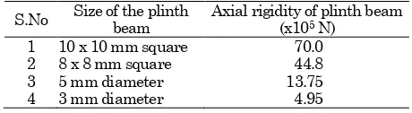
where Em is modulus of elasticity of model, Ep is modulus of elasticity of prototype, Im is moment of inertia of model, Ip is moment of inertia of prototype, and 1/n is scale factor for length. An aluminum tube with an outer diameter of 16 mm and inner diameter of 12 mm was selected as the model pile with a length scaling factor of 1/10. This is used to simulate the prototype pile of 350 mm diameter solid section made of reinforced concrete. Columns of height 3.2 m, beam of span 5 m and plinth beam of the plane frame were scaled in the same manner. Rigidity of plinth beam is varied by using 10x10 mm square bar, 8x8 mm square bar, 5 mm diameter round bar and 3 mm diameter round bar of aluminum. The rigidity values of plinth beams used in the study are tabulated in Table 1.
Table 1. Rigidity of Plinth Beam
S.No Size of the plinth beam
Axial rigidity of plinth beam (x105 N)
1 10 x 10 mm square 70.0
2 8 x 8 mm square 44.8
3 5 mm diameter 13.75
Aluminum plates of 13 mm thickness were used as the pile caps. In the pile group setup, pile spacing of eight diameter (8D) was adopted and the length of the piles was so selected as to maintain a length to diameter (L/D) ratio of 20 [13]. A sufficient free standing length (of about 20 mm) was maintained from the bottom of the pile cap to the top of the soil bed, because the pile cap is modeled as rigid and its interaction with the soil is neglected. Beam column junctions were made by welding for the fixed condition. Screwing of the piles and columns in the threads provided in the pile cap leads to partial fixity condition. The scaling factors used in the study are presented in Table 2.
Table 2. Scaling Factors Used in the Study
Variable Length Density Stiffness Stress Strain Force Scaling
Factors
1/10 1 1/10 1/10 1 1/103
Experimental setup and Instrumentation
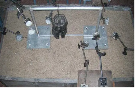
The photographs of the test setup are shown in Figure 1a-1d. Tests were conducted on the model pile groups with the frame embedded in sand bed in a tank, which was well instrumented with the dial gauges of sensitivity 0.002 to study the lateral, vertical displacements and rotations at the base of the column. Loads on the frame were applied through the hooks provided to the beam at required locations according to the type of loads on the beam. The model frame was placed at the centre of the tank using the templates. The sand is then poured in the tank gently through the pores of a steel tray in layers to attain the loose state (relative density of 35%) and uniformity for the sand bed. The installation procedure simulates the bored pile condition.
Figure 1a. Photograph of Instrumented Model Frame with Plinth Beam
Figure 1b. Photograph of Model Frame with Plinth Beam for Central Point Load
Figure 1c. Photograph of Model Frame with Plinth Beam for UDL
Figure 1d. Photograph of Model Frame with Plinth Beam for Eccentric Point Load
Test Procedure
Testing Phases
Static vertical load tests were conducted on the model frame with plinth beam supported on pile groups embedded in the sand bed shown in Figure 2. Tests were conducted for the following cases:
1. Central concentrated load is applied in incre-ments (1, 2, 3 kg up to 15kg) at the centre of the beam.
2. Uniformly distributed load (UDL) is simulated by loading the beam at third points with equal loads in increments (3, 6, 9 kg up to 18kg.).
3. Eccentric concentrated load is applied in incre-ments (1, 2, 3 kg up to 15kg.) at a nominal eccentricity of 10% of the span of the beam.
Analytical Programme Using Ansys [14]
The analysis of the model plane frame with plinth beam is carried out using ANSYS for the following cases:
i) Nonlinear analyses to evaluate the lateral dis-placements, vertical displacements and rotations, shear forces and bending moments in the frame; and
ii) Frame with bases released by imposing the lateral displacements, vertical displacements and rotations measured from the experiments for the corresponding loading on the frame to get the back calculated shear forces and bending moments generated in the frame members.
Nonlinear Finite Element Analysis (Nonlinear FEA)
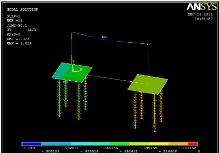
The nonlinear analyses were performed for the single bay single storey model plane frame with plinth beam founded on 2 x 2 pile groups in a sandy soil (Figure 2a-2c). The columns, beams and piles are modeled using the 3D elastic two nodded BEAM elements. The pile cap is modeled using the four nodded elastic SHELL elements. The soil around the individual piles was modeled with nonlinear load transfer curves using the COMBIN39 elements.
Figure 2a. Modeling of the Frame with Plinth Beam Along with the Pile Groups
Figure 2b. Deformed Shape of Model for Central Point Load
Figure 2c. Deformed Shape of Model for Eccentric Point Load
The nonlinear constitutive soil models given by Equations 2-4 are employed for the present problem.
The lateral load transfer curves given by the American Petroleum Institute (API) model [15] is given by the Equation 2,
̅ ̅ (2)
where Ās is the adjustment coefficient for the static p-y curves; Ps, governing ultimate soil resistance; k,
initial subgrade reaction constant; Z, depth; and Pu, ultimate soil resistance.
The axial load transfer curves (-Z and Q-Z) suggested by McVay et al. [16] are used in this study. The vertical -Z springs along the side of the pile is given by the Equation 3 [16],
(3)
where = r00/f;
r
o is the radius of the pile; 0, shearshear stress is negligible; Gi, initial shear modulus; f, ultimate shear stress at the point of interest on the pile.
As for the nonlinear tip spring (Q-Z), the following relation given by the Equation 4 is used [16]:
(evaluated from the laboratory experiments),
Poisson’s ratio (a typical value of 0.3 is used),
ultimate skin friction f(evaluated from Tomlinson’s [17] equation), ultimate tip resistance Qf, and shear modulus Gi [18].
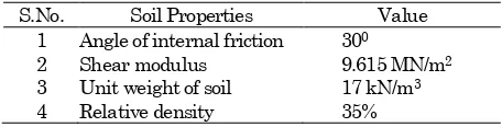
Table 3. Soil Properties used in the Study
S.No. Soil Properties Value
1 Angle of internal friction 300
2 Shear modulus 9.615 MN/m2
3 Unit weight of soil 17 kN/m3
4 Relative density 35%
The frame is loaded with a central concentrated load, UDL, and eccentric concentrated load at a nominal eccentricity of 10% of length of the beam (with eccentricity measured from the center of the beam) in increments as applied in the experimental program. The response in terms of deformations, rotations, back calculated shear forces and bending moments is obtained for each load increment.
Results and Discussion
Lateral Displacement, Settlement and Rotation at the Base of the Column
Figures 3a and 3b represent the variation of the lateral displacement with the static load applied as central concentrated load and uniformly distributed load. From the plots shown herein, it is observed that the lateral displacement at the base of the column in both cases increased by about 95% as the axial rigidity of the plinth beam reduced by 93% (Table 1).
Figures 4a and 4b represent the variation of the lateral displacement with the static load applied on the frame as eccentric concentrated load.
From the plots shown herein, it is observed that the behaviour of frame with eccentric concentrated load (Figs 4a and 4b) is different from that of the frame with central concentrated load (Figure 3a and 3b) and uniformly distributed load. In case of frame with central concentrated load and uniformly distributed load, the bases of the columns moves outward when the load is applied on the frame, but in case of frame with eccentric concentrated load the base of column at near end and far end moves in the same direction towards the eccentricity. It is observed that the lateral displacement at the base of the column increased by about 40% as the rigidity of the plinth beam reduced by 93%. The displacement from the experiment shows a variation of less than 15% with respect to that from the nonlinear FEA. For example, frame with 3 mm diameter plinth beam analytical solution gives lateral displacement of 0.043 mm, while the experimental result gives 0.048 mm under a central concentrated load of 150N. The variation of experimental value with respect to that from the nonlinear FEA is 10.42%. Hence, the displacement from the experiment is in good agreement with that by the nonlinear FEA.
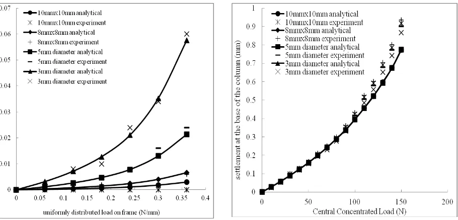
The variation of settlement at the base of the column with respect to the central concentrated load and UDL on the frame is presented in Figures 5a and 5b, respectively, and the variation of settlement at the base of the column at the near end and far end to the load for the frame under the eccentric concentrated load is presented in Figures 6a and 6b, respectively. The plots show that, the effect of variation of rigidity of plinth beam on settlement is negligible.
Figure 3b. Lateral Displacement at the Base of the Column (UDL)
Figure 4a. Lateral Displacement at Near End (Eccentric Concentrated Load)
Figure 4b. Lateral Displacement at Far End (Eccentric Concentrated Load)
Figure 5a. Settlement at the Base of the Column (Central Concentrated Load)
Figure 5b. Settlement at the Base of the Column (UDL)
Figure 6a. Settlement at Near End (Eccentric Concen-trated Load)
Figure 6b. Settlement at Far End (Eccentric Concentrated Load)
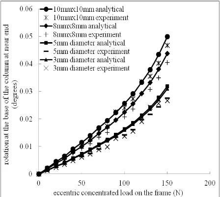
The variation of rotation at the base of the column for the central concentrated load and UDL applied on the frame is presented in Figures 7a and 7b, respectively. Meanwhile, the variation of rotation at the column base of the near and far end, respect-tively, of the frame under the eccentric concentrated load is presented in Figures 8a and 8b. From the plots mentioned herein, it is observed that, as the rigidity of the plinth beam reduced by 93% the rotation at the base of the column increased by about 30%. In case of eccentric concentrated load on the frame, after certain level of loading, rotation at the far end changed from clockwise (+) to anti-clockwise (-). This is expected because of the lateral movement of the near end and far end are in the same direction which causes the far end to rotate in the reverse manner. The rotations from the experiment show a variation of not more than 15% with respect to that from the nonlinear FEA. Hence the rotation from the experiment is in good agreement with that by the nonlinear FEA.
Figure 7a. Rotation at the Base of the Column (Central Concentrated Load)
Figure 7b. Rotation at the Base of the Column (UDL)
Figure 8a. Rotation at Near End (Eccentric Concentrated Load)
Shear Force in the Frame by Experiments and Nonlinear FEA
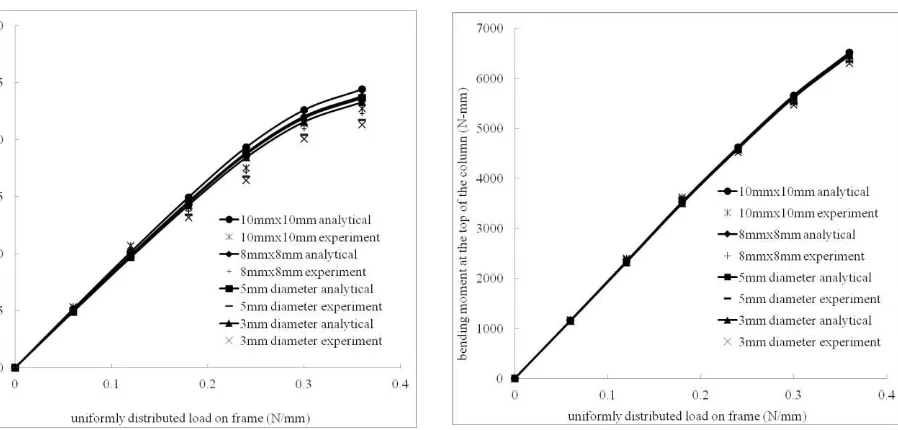
The shear force in the frame under the central concentrated load, UDL, and eccentric concentrated load have been plotted in Figures 9a-9c, respectively. From these plots, it can be observed that for relatively lower loads on the frame, the shear force predicted by the nonlinear FEA and experiment are linear. As the rigidity of the plinth beam reduces by 93% the shear force also reduces by about 5%. The shear force obtained from the experiment deviates by not more than 3% of that given by the nonlinear FEA, which indicates that the nonlinear soil model is in good agreement with the experimental results.
Figure 9a. Shear Force (Central Concentrated Load)
Figure 9b. Shear Force (UDL)
Figure 9c. Shear Force (Eccentric Concentrated Load)
Figure 10a. Bending Moment at the Top of the Column (Central Concentrated Load)
Bending Moment at Top of the Column by Experiments and Nonlinear FEA
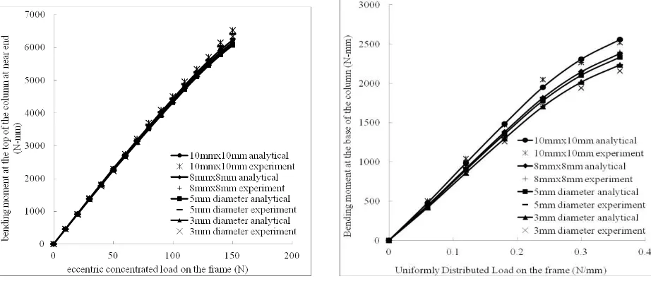
The bending moment at the top of the column of the frame under the central concentrated load and UDL is plotted in Figures 10a and 10b, respectively, and the one of the near end and far end, respectively, of the frame under the eccentric load is plotted in Figures 11a and 11b. From the above figures, it is observed that as the rigidity of plinth beam reduces by 93% the bending moment at the top of the column reduces by about 2-3%. The point to be noted with respect to the bending moments at the top of the column of the frame predicted by different methods is that, though the percentages of variation may not be great, the differences are still significant because the magnitudes of bending moment are of multiples of thousands. This indicates the need for considera-tion of soil interacconsidera-tion in evaluating the design parameters in a building frame. The values of bending moment predicted by the nonlinear FEA and experiments differ by not more than 1%, which indicates that the nonlinear soil model is well suited for representing the nonlinear behavior of soil.
Bending Moment at the Base of the Column by Experiments and Nonlinear FEA
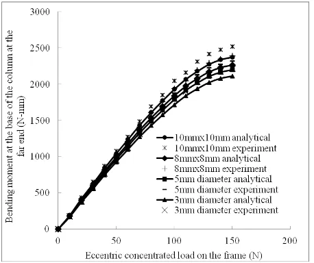
The variation of bending moment at the base of the column of the frame under the central concentrated load and UDL has been plotted in Figures 12a and 12b, respectively. Figures 13a and 13b show the variation of bending moment at the base of the column of the near end and far end, respectively, of the frame under the eccentric concentrated load. These figures show that, the bending moment reduces by 15% as the rigidity of the plinth beam reduces by 93%. The bending moments given by the experiments agree well with those by the nonlinear FEA with a variation of not more than 5% indicating that the soil nonlinearity is well represented by the constitutive relations used for the soil.
Figure 11a. Bending Moment at Top of Column at Near End (Eccentric Concentrated Load)
Figure 11b. Bending Moment at Top of Column at Far End (Eccentric Concentrated Load)
Figure 12a. Bending Moment at the Base of the Column (Central Concentrated Load)
Figure 13a. Bending Moment at Base of Column at Near End (Eccentric Concentrated Load)
Figure 13b. Bending Moment at Base of Column at Far End (Eccentric Concentrated Load)
Conclusions
Based on the results of the present experimental and numerical investigations on the model pile groups supported frame, the following conclusions are drawn:
a) As the rigidity of plinth beam decreases, the lateral displacement and rotation at the base of the column increases. The effect of variation of rigidity of plinth beam on settlement is negligible. For eccentric concentrated load on the frame after certain level of loading rotation at the far end is changing its sign for relatively higher rigidity of the plinth beam as the lateral displacements at near end and far end are in the same direction. The displacements and rotations from the experimental results and the nonlinear FEA show a maximum difference of not more than
15%, indicating that the nonlinear curves used to characterize the soil behavior are generally good for representing the load-displacement response of the soil.
b) For relatively lower loads on the frame the variation of shear force is linear and it is nonlinear for higher loads. As the rigidity of the plinth beam reduces by 93%, the shear force also reduces by 5%.
c) As the rigidity of the plinth beam reduces by 93%, the bending moment at the top of the column also reduces by about 2-3% which is still significant as the values are multiples of thousand.
d) As the rigidity of the plinth beam reduces by 93%,
1. Chamecki, C., Structural Rigidity in Calculating Settlements, Journal of Soil Mechanics Founda-tion Division ASCE, 82(1), 1956, pp. 1-19.
2. Morris, D., Interaction of Continuous and Frames and Soil Media, Journal of Structural
DivisionASCE, 5, 1966, pp. 13-43.
3. Lee, I.K. and Brown, P.T., Structures and Foun-dation Interaction Analysis, Journal of
Struc-tural DivisionASCE, 11, 1972, pp. 2413-2431.
4. Subbarao, K.S., Shrada Bai, H., and Raghuna-tham, B.V., Interaction Analysis of Frames with Beam Footing, Proceedings of Indian
Geotech-nical Conference(IGC-1985), Roorkee, 1985.
5. Deshmukh, A.M. and Karmarkar, S.R., Interac-tion of Plane Frames with Soil, Proceedings of
Indian Geotechnical Conference (IGC-1991),
Surat, India, 1991.
6. Srinivasa Rao, P., Rambabu, K.V., and Allam, M.M., Representation of Soil Support in Analy-sis of Open Plane Frames, Computers & Struc-tures, 56, 1995, pp. 917-925.
7. Noorzaei, J., Viladkar, M.N. and Godbole, P.N., Elasto-Plastic Analysis for Soil–Structure Interaction in Framed Structures, Computers & Structures, 55(5), 1995, pp. 797–807.
9. Chore, H.S., Ingle, R.K., and Sawant, V.A., Build-ing Frame – Pile Foundation – Soil Interaction Analysis: A Parametric Study, Interaction and Multiscale Mechanis, 3(1), 2010, pp. 55-79.
10. Prakoso, W.A., CPT-Based Interpretation of Pile Load Tests in Clay-Silt Soil, Civil Engineering Dimension, 13(1), 2011, pp. 6-14.
11. Ravi Kumar Reddy, C., and Gunneswara Rao, T. D., Experimental Study of A Modeled Building Frame Supported by Pile Groups Embedded in Cohesionless Soil. Interaction and Multiscale Mechanis, 4(4), 2011, pp. 321-336.
12. Wood, D. M., Crewe, A., and Taylor, C., Shaking Table Testing of Geotechnical Models, IJPMG, 2002, pp. 01-13.
13. Chandrasekaran, S.S. and Boominadhan, A., Group Interaction Effects on Laterally Loaded Piles in Clay, Journal of Geotechnical and
Geoenvironmental Engineering, ASCE, 136,
2010, pp. 573-582.
14. ANSYS Inc., General Finite Element Analysis Program, Version 10.0 ANSYS, Inc., Canons-burg, Pa, 1996.
15. American Petroleum Institute., Recommended Practice for Planning, Designing, and Con-structing Fixed Offshore Platforms, API
Recom-mended Practice, 2A (RP-2A), 17th edn, 1987.
16. McVay, M.C., Townsend, F.C., Bloomquist, D.G., O’Brien, M., and Caliendo, J.A., Numerical Analysis of Vertically Loaded Pile Groups, Proc., Foundation Engineering: Current Principles and Practices, Vol. 1, ASCE, New York, 1989, pp. 675-690.
17. Tomlinson, M.J., Some Effects of Pile Driving on Skin Friction, Proceedings of International Con-ference on Behavior of Piles, Institution of Civil Engineers, London, 1971.