International Conference and Exhibition on Sustainable Energy and Advanced Materials (ICE SEAM 2011) Solo-Indonesia. October 3-4, 2011.
291
|
I C E S E A M 2 0 1 1
Effects of Load Secondary Voltage on Resistance Spot Weldability of
Dissimilar Metals Joint between SUS316L and J4
Martinus Heru P, Triyono, Wijang Wisnu R, Eko Prasetya Budiana
Mechanical Engineering Department, Sebelas Maret University E-mail : [email protected]
Abstract
Solar panels are usually placed in open spaces like the roof of a house or building. Stainless steels are used for its supporting components due to an excellent combination of strength and corrosion resistance. However, a high nickel content in conventional stainless steel is expensive and not environmentally friendly. Low nickel stainless steels such as J4 have been developed to meet economic and environment reasons. In application, partially substitution of conventional stainless steel by low nickel stainless steel makes dissimilar materials joint case. In this study, the influence of the primary welding parameters affecting the heat input such as load secondary voltage on the morphology, microhardness, and tensile shear load bearing capacity of dissimilar welds between SUS316L and J4 has been investigated. It was found that the tensile shear load bearing capacity of welded materials increases with an increasing load secondary voltage due to the enlargement of nugget size. Although, an acceptable joint strength was obtained at 2.02 volt, the optimum welding parameters producing maximum joint strength were established at a voltage of 2.67 volt, where the electrode force and weld time were constant. Increasing load secondary voltage changed failure mode from interfacial fracture to pullout fracture of J4 sheet metals.
Keywords: resistance spot welding, dissimilar metals joint, scondary voltage, SUS 316L, Jindal Stainless Steel J4.
1.
Introduction
The file name of the final paper must be the same as the title of the paper. The length of submitted papers should be 8 pages in maximum, including references, figures and tables. If the paper exceeds eight pages, extra pages will be truncated. We expect all texts to be written in good English and that grammar and spelling have been checked before submission. The case of matter (main body) should at least contain the following sections: Introduction, Methodology, Results and Discussion, and Conclusions.
International Conference and Exhibition on Sustainable Energy and Advanced Materials (ICE SEAM 2011) Solo-Indonesia. October 3-4, 2011.
292
|
I C E S E A M 2 0 1 1
2.
Methodology
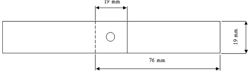
In this study, a series of SUS 316L and austenitic stainless steel J4 couples were selected and welded by electrical resistance spot welding by fixing electrode form, materials type, cooling water flow rate and electrode force and changing welding current by secondary voltage loads. All series were exposed to tensile-shear tests in order to determine the joint strengths and microhardness test in order to determine the distribution of hardeness in weld metal. The welded parts were exposed to tensile-shear a testing machine and microhardess tests in laboratory conditions. The tensile speed was remained constant during test. The values given as tensile-shear strength are the maximum values read from the scale of the machine. Materials used in this study is the stainless steel plate SUS 316 L and J4 1 mm thick with a size of 76 mm x 19 mm. The chemical composition of both the base metal is given in Tabel 1 and the sizes of specimens are shown in Figs.2. Welding is done by electric resistance welding (RSW) using water as a cooling cone Cu-Cr electrodes, the diameter contact surface is 6 mm.
Table 1. Chemical composition of steel sheets used in experiments.
Material C% Mn% P% S% Si% Cr% Ni% N% Cu%
J4 0,1 8,5 0,09 0,03 0,75 15-17 1,0-1,5 0,2 1,5-2,0
SUS 316 L 0,03 2,0 0,45 0,03 0,75 16-18 10,-14 0,1 2,0-3,0
The tensile-shear tests specimens are prepared as shown in Figs. 2 and cleaned. After that, these parts were overlapped with 19 mm spacing and welded. The electrode force was fixed at 6 kN and controlled during experiments. Clamping and hold times were remained constant as 2,5 sec in all series. The welding current voltage was increased from 1.6 volts, 2.02 volts and 2.67 volts.
Figure. 2 ANSI/AWS standard dimension for spot weld test
Microhardness test samples are prepared as shown in Figs. 3. The weld joint was in the middle of the spot weld to obtain the cross section of the weld. These cross sectioned samples were then cut into small pieces with length about 10 mm by using cutting machine. The reason for this step is to make the samples easier to be cold mounted. A few small pieces of PVC pipe have been cut as the moulds for cold counting. Then, a resin mixture with the composition of 98% resin and 2% catalyzer has been made. The PVC moulds were then placed on the flat tile and sealed with clay to avoid the resin mixture from leaking. The cold mounted samples were ground and polished. Grinding was carried out using abrasive sand papers that have grades such as 240, 360, 400,600, 800,1000, and 1200. Once polished, the specimens performed etching process mixture of HCl, HNO3 (Aq) and alcohol.
International Conference and Exhibition on Sustainable Energy and Advanced Materials (ICE SEAM 2011) Solo-Indonesia. October 3-4, 2011.
293
|
I C E S E A M 2 0 1 1
3.
Results and Discussion
3.1. Effect of Secondary Voltage on weld quality.
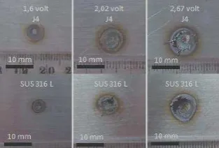
The most important factors that affect weld quality are surface appearance, strength and ductility, weld nugget size, weld penetration, sheet separation, and internal discontinuities (AWS Welding Handbook 7th ed). Surface appearance of the welded dissimilar materials is shown in Fig. 4. Normally the surface appearance of a spot weld should be relatively smooth; round or oval in the case of contoured work; and free from surface fusion, electrode deposits pits, cracks and deep electrode indentation (AWS Welding Handbook 7th ed). In this study, the smooth weld surface appearance is almost obtained (Fig. 4).
Figure. 4. Macrograph of the resistance spot welded materials
The nugget size of J4 steel side of welded materials was found bigger than that of SUS 316L (Fig. 4). In addition, it was also found that the weld nugget lost its symmetric form because of the unbalanced heat resulting from different physical properties of the steel sheets. As known the heat balance may present a problem when spot welding together unequal thickness of the same metal, equal thicknesses of two metals with a significant difference in electrical conductivities, or a combination of the two (A. Hasanbas_og˘ lu and R. Kac,ar, 2007 ) . Electrode configurations and compositions can be used to overcome unbalanced heating to some extent (AWS Welding Handbook 7th ed). The difference is estimated nugget surface appearance of the electrical resistance the greater of the electrode and base metal surface that is affected by the increase of peak secondary voltage (1,6; 2,02; 2,67 volts).
3.2. Effect of of Secondary Voltage on on tensile-shear strength.
In order to determine weld quality of dissimilar materials, the strength of weldment was also determined. Structures employing spot weld are usually designed so that the welds are loaded in shear when the parts are exposed to tension or compression loading. In some cases, the welds may be loaded in tension, where the direction of loading is normal to the plane of the joint, or a combination of tension and shear (AWS Welding Handbook 7th ed).
Figure.5: The tensile-shear tests specimens of the resistance spot welded materials
International Conference and Exhibition on Sustainable Energy and Advanced Materials (ICE SEAM 2011) Solo-Indonesia. October 3-4, 2011.
294
|
I C E S E A M 2 0 1 1
Table 2.Mechanical properties of resistance spot welded materials.
Sample Yeild Strength
(Mpa)
Tensile Strength
(Mpa ) E ( % )
SUS 316 L base metal 170 485 50
J 4 base metal 350 700 50
Secondary voltage (volt ) Tensile Shear Force (kN) Failure
1,2 - 6,35 interfacial
2,02 - 8,64 pullout
2,6 - 11,65 pullout
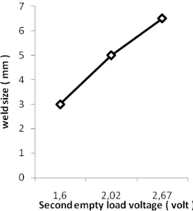
The nugget size is also an important critical parameter in determination of spot weld quality (AWS Welding Handbook 7th ed). Therefore, the diameter or width of the fused zone must meet the requirements of the appropriate specifications or the design criteria. The relationship between nugget size and peak weld voltages was determined in this study. The result is shown graphically in Fig. 7. Increasing peak weld voltages cause high heat input to weld zone and extending weld nugget, so the tensile-shear strength of joints increases. The enhancement in tensile shearing load bearing capacity of weldment with increasing of secondary voltage is primarily attributed to the enlargement of nugget size.
Excessive heat energy input causes void and crack formations, partially spurt out of molten metal and so, the tensile-shear strength of joint decreases. During the tests, three types of breaking failure were observed as; (a)
separation, (b) knotting and, (c) tearing. Samples of them are shown in Fig. 8 Figure. 6 Second voltage effect on
tensile shear force of joints
International Conference and Exhibition on Sustainable Energy and Advanced Materials (ICE SEAM 2011) Solo-Indonesia. October 3-4, 2011.
295
|
I C E S E A M 2 0 1 1
Figure 8. Breaking types observed in tensile-shear tests.
Sheet separation which is one of the factors that affects the spot weld quality occurs at faying surfaces due to the expansion and contraction of the weld metal and the forging effect of the electrodes on the hot nugget (AWS Welding Handbook 7th ed). During this study, normal separations were obtained in 1,6 volt, when fracture take place within the weld interface of welded materials. And that the failure was occurred by knotting and tearing of J4 sheet metals side of spot welded materials in 2,02 volt and 2,67 volt. In these materials, the samples joined with 2,02 volt and 2,67 volt peak voltage resulted fracture starting from outer region of the HAZ of J4 side of weldment. Results confirmed that with increasing in energy input, the region of failure shifts from the interface to the outer region of HAZ.
3.3. Effect of Secondary Voltage on Microhardness test.
International Conference and Exhibition on Sustainable Energy and Advanced Materials (ICE SEAM 2011) Solo-Indonesia. October 3-4, 2011.
296
|
I C E S E A M 2 0 1 1
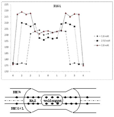
Figure. 9 Hardness profiles of welded materials
As seen in Fig. 9, an important difference in hardness value was observed among weld nugget, HAZ’s and base metals in both side of weldment due to nature of dissimilar materials chemical composition. Results show that weld nugget and HAZ hardness of 316 L of welded materials lower than that of J4 stainless steel. As seen in Table 1, The chemical composition of base metals J4 in which there is so much alloying elements such as carbon and manganese that affects the hardenability. Spot welds in thin sheet can have relatively high hardness when the carbon content exceeds about 0.08% (Tewari, S. P and Nitin Rathod, 2010). It was not observed any fluctuations in hardness values of both side of weldment related with peak weld voltages (1,6; 2,02; 2,67 volts), because of chemical composition of base metals in which there is not too much alloying elements that affects the hardenability (Hasanbasoglu, A. and Kacar, R., 2007).
3.4. Effect of Secondary Voltage on microstructure of weldments.
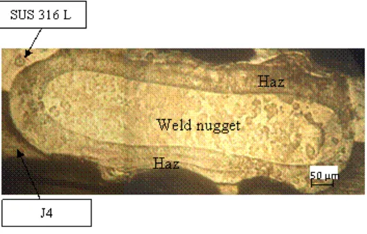
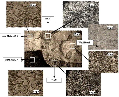
The optical micrographs of the weld nugget, HAZ and transition region from HAZ to base metal in the weldments are shown in Fig. 10. As seen in Fig. 10, the weld nugget has a columnar structure. An increasing in energy input caused coarsening of the microstructure of weld nugget and also of HAZ (Aslanlar et al., 2007). When the images are generally evaluated, the microstructures of these areas are considerably different from those of originalbase metal (Hasanbasoglu et al.., 2007). Unlike the base metal, it is noted that grain growth occurs due to the heat transfer. Therefore, the area of HAZ grain growth region was found wider on J4 side of weldment that have higher thermal coefficient compared with SUS 316 L, are shown in Fig. 11.
Figure 10. Macro structure of a dissimilar resistance spot weld between 316L and J4
International Conference and Exhibition on Sustainable Energy and Advanced Materials (ICE SEAM 2011) Solo-Indonesia. October 3-4, 2011.
297
|
I C E S E A M 2 0 1 1
Figure 11. Micro structure of a dissimilar resistance spot weld between 316L and J4
4.
Conclusions
• Although an acceptable joint strength was obtained at weld secondary voltage of 1,6 and 2,02 volt, the optimum welding parameters producing maximum joint strength were established at a 2,6 volt weld.
• It was found that the tensile shear load bearing capacity of welded materials increases with an increasing peak weld current by secondary voltage due to the enlargement of nugget size. The nugget size of J4 steel side of welded materials was found larger than that of 316 L.
• The failure occurred by tearing of J4 sheet metals side of spot welded materials in 2,02 ; 2,6 volt. The primary cause of weakening of the weldment is identified as the excessive grain growth region of HAZ in J4. The increase in energy input caused coarsening of the microstructure of weld nugget and also of HAZ.
• It was not observed any fluctuations in hardness values of both side of weldment related with peak weld voltages. weld nugget and HAZ hardness of 316 L of welded materials lower than that of J4 stainless steel.
• The increase in heat input related with current caused coarsening of the microstructure of weld nugget and also of HAZ. The grains formed on the base metals were oriented to J4 sheet metals. where the heat transfer is much faster than stainless steel sheet.
References
Alenius. M., et al. (2006) ‘Exploring The Mechanical Properties Of Spot Welded Dissimilar Joints For Stainless And Galvanized Steels’, Welding Journal.
International Conference and Exhibition on Sustainable Energy and Advanced Materials (ICE SEAM 2011) Solo-Indonesia. October 3-4, 2011.
298
|
I C E S E A M 2 0 1 1
Cui Y, Lundin CD, Hariharan V. (2006) ‘Mechanical behavior of austenitic stainless steel weld metals with microfissures’,J Mater Process Technol, Vol.171, No.1, pp.150–5
Dursun O¨ zyu¨rek (2007) An effect of weld current and weld atmosphere on the resistance spot weldability of 304L austenitic stainless steel, Department of Metal Education, ZKU, Karabu¨k Technical Faculty, Karabu¨k 78100, Turkey, Received 21 July; accepted 2 March
Gu¨lenc¸ B., Develi K., Kahraman, N., Durgutlu (2005) ‘An Experimental study of the effect of hydrogen in argon as a shielding gas in MIG welding of austenitic stainless steel’,Int J Hydrogen Energ, Vol.30, pp(13–14):1475–81.
Hasanbasoglu, A. and Kacar, R. (2007) ‘Resistance spot weldability of dissimilar materials (AISI 316L-DIN EN 10130-99 steels)’. Materials and Design, vol.2, pp.1794–1800.
Metal and Their Weldability. (1982) AWS Welding Handbook vol .4 , United States of America: American Welding Society.
Reiter, A.E., Brunner, B., Ante M., Rechberger, J. (2006) ‘Investigation of several PVD coatings for blind hole tapping in austenitic stainless steel’,Surf Coat Tech, Vol.200, No.18–19, pp.5532–41.
Shamsul, J.B. and Hisyam, M.M. ( 2007) ‘Study Of Spot Welding Of Austenitic Stainless Steel Type 304’,
Journal of Applied Sciences Research, INSInet Publication, Vol.3, No.11, pp.1494-1499.
Singhal, L.K. (2006) ‘Use Of Chrome Manganese Austenitic Stainless Steel In Sugar Industry – A Conceptual Aprroach’, Jindal Stainless Limited.
Tewari S. P., Rathod, N. (2010) ‘Resistance Spot Weldability of Low Carbon and HSLA Steels’, Thammasat Int. J. Sc. Tech., Vol. 15, No. 1.