Understanding TCP/IP
A clear and comprehensive guide to TCP/IP
protocols
Libor Dostálek
Alena Kabelová
Understanding TCP/IP
A clear and comprehensive guide to TCP/IP protocols
Copyright © 2006 Packt Publishing
All rights reserved. No part of this book may be reproduced, stored in a retrieval system, or transmitted in any form or by any means, without the prior written permission of the publisher, except in the case of brief quotations embedded in critical articles or reviews.
Every effort has been made in the preparation of this book to ensure the accuracy of the
information presented. However, the information contained in this book is sold without warranty, either express or implied. Neither the authors, Packt Publishing, nor its dealers or distributors will be held liable for any damages caused or alleged to be caused directly or indirectly by this book. Packt Publishing has endeavored to provide trademark information about all the companies and products mentioned in this book by the appropriate use of capitals. However, Packt Publishing cannot guarantee the accuracy of this information.
First published: April 2006
Production Reference: 1130406
Published by Packt Publishing Ltd. 32 Lincoln Road
Olton
Birmingham, B27 6PA, UK. ISBN 1-904811-71-X www.packtpub.com
Cover Design by www.visionwt.com
This is an authorized and updated translation from the Czech language.
Credits
Authors Libor Dostálek Alena Kabelová
Contributing Authors Marta Vohnoutová Luděk Rašek Michal Hojsík
Technical Editors Abhishek Shirodkar Darshan Parekh
Development Editor Louay Fatoohi
Editorial Manager Dipali Chittar
Indexer
Abhishek Shirodkar
Proofreader Chris Smith
Production Coordinator Manjiri Nadkarni
Illustrator
Shantanu Zagade
About the Authors
Libor Dostálek was born in 1957 in Prague, Czech Republic. He graduated in mathematics at the Charles University in Prague. For the last 20 years he has been involved in ICT architecture and security. His experiences as the IT architect and the hostmaster of one of the first European Internet Service Providers have been used while writing this publication.
Later he became an IT architect of one of the first home banking applications fully based on the PKI architecture, and also an IT architect of one of the first GSM banking applications (mobile banking). As a head consultant, he designed the architecture of several European public certification service providers (certification authorities) and also many e-commerce and e-banking applications. The public knows him either as an author of many publications about TCP/IP and security or as a teacher. He has taught at various schools as well as held various commercial courses. At present, he lectures on Cryptology protocols at the Charles University in Prague.
He is currently an employee of the Siemens.
Alena Kabelová was born in 1964 in Budweis, Czech Republic. She graduated in ICT at the Economical University in Prague. She worked together with Libor Dostálek as a hostmaster. She is mostly involved in software development and teaching. At present, she works as a senior project manager at the PVT and focuses mainly on electronic banking.
Acknowledgements
This book has a long history. In every new edition, there were new chapters and sections added by different co-authors. We extend our special thanks to our following co-authors:
• Luděk Rašek wrote Chapter 17 (Lightweight Directory Access Protocol).
• Marta Vohnoutová wrote section 4.7 (Wireless Local Area Network).
• Michal Hojsík wrote section 7.4.2 (Link State Protocols).
Table of Contents
Preface 1
Chapter 1: Introduction to Network Protocols
5
1.1 ISO OSI 8
1.1.1 Physical Layer 8
1.1.2 Data Link Layer 9
1.1.3 Network Layer 11
1.1.4 Transport Layer 12
1.1.5 Session Layer 13
1.1.6 Presentation Layer 13
1.1.7 Application Layer 13
1.2 TCP/IP 14
1.2.1 Internet Protocol 14
1.2.2 TCP and UDP 14
1.2.3 Application Protocols 15
1.3 Methods of Information Transmission 16
1.3.1 Synchronous Transmission 16
1.3.2 Packet Transmission 17
1.3.3 Asynchronous Transmission 17
1.4 Virtual Circuit 18
Chapter 2: Network Monitoring Tools
21
2.1 Packet Drivers 22
2.2 MS Network Monitor 23
2.2.1 Frame Capturing 23
2.2.2 Viewing Captured Frames 26
2.2.3 Filters for Displaying Captured Frames 28
2.3 Ethereal 28
Table of Contents
Chapter 3: Physical Layer
33
3.1 Serial Line 34
3.1.1 Serial and Parallel Data Transport 34 3.1.2 Symmetrical and Asymmetrical Signals 34 3.1.3 Synchronous and Asynchronous Transport 35 3.1.4 V.24, V.35, and X.21 Protocols 36
3.1.5 Null Modem 40
3.2 Modems 40
3.2.1 Dial-Up Connection 41
3.2.2 Leased Lines 41
3.2.3 Automatic Modem 42
3.2.3.1 AT Commands 42
3.2.4 Synchronous Transmission 44
3.2.5 Baseband, Voice Band, and ADSL 44
3.2.6 Transmission Rate 49
3.2.6.1 The V.90 Recommendation 49
3.2.7 Data Compression 50
3.2.8 Error Detection 51
3.3 Digital Circuits 51
3.3.1 ISDN 51
3.3.1.1 Basic Rate 52
3.3.1.2 Higher Layer Protocols and Signalization 54
3.3.2 E and T Lines 56
3.4 LAN 57
3.4.1 Structured Cables 57
3.4.1.1 Copper Distribution 58
3.4.1.2 Optical Fibers 59
3.4.2 Ethernet (10 Mbps) 62
3.4.2.1 AUI 62
3.4.2.2 BNC 62
3.4.2.3 Twisted-Pair 62
3.4.3 Fast Ethernet (100 Mbps) 63
3.4.4 Gigabyte Ethernet (1 Gbps) 63
Chapter 4: Link Layer
65
4.1 Serial Line Internet Protocol 65
Table of Contents
4.3 High-Level Data Link Control Protocol 71
4.3.1 Flag 72
4.3.4 Data Field and a Transferred Protocol Type 76
4.3.5 Checksum 77
4.3.6 HDLC Protocol Summary 77
4.4 Point-To-Point Protocol 77
4.4.1 Dialing a Phone Line 80
4.4.2 Link Control Protocol 81
4.4.3 Authentication 87
4.4.3.1 Password Authentication Protocol 88
4.4.3.2 Challenge Handshake Authentication Protocols 89
4.4.3.3 Extensible Authentication Protocol 90
4.4.3.4 Radius Protocol 91
4.4.4 Call-Back Control Protocol 92
4.4.5 Other Protocols 94
4.4.5.1 Multilink Protocol 94
4.4.5.2 Bandwidth Allocation Protocol and Bandwidth Allocation Control Protocol 96
4.4.5.3 Compression Control Protocol 97
4.4.5.4 Encryption Control Protocol 98
4.4.5.5 Setting Encryption Keys 98
4.4.6 Internet Protocol Control Protocol 99
4.5 Frame Relay 101
4.5.1 A Frame Relay Protocol Frame 105
4.5.2 IP Through Frame Relay 108
4.5.3 Local Management Interface 110 4.5.4 Frame Relay Configuration on CISCO Routers 110
4.5.5 Frame Relay Protocol 110
4.6 Local Area Networks 111
4.6.1 Ethernet 112
4.7 Wireless Local Area Network 121
4.7.1 Typical WLAN Configuration 123
4.7.1.1 Peer-To-Peer Networks 123
4.7.1.2 Access Point 123
4.7.1.3 Roaming (Several Access Points) 124
4.7.1.4 Backbone Point-to-Point Connection 124
Table of Contents
4.7.2 Antennas 124
4.7.3 Security of WLAN 125
4.7.3.1 Service Set ID 125
4.7.3.2 Wired Equivalent Privacy 125
4.7.3.3 IEEE 802.1X 126
4.8 Fixed Wireless Access 127
4.8.1 The Differences Between FWA and WLAN 127 4.8.2 The Main Benefits of FWA 128
Chapter 5: Internet Protocol
129
5.1 IP Datagram 133
5.2. Internet Control Message Protocol 137
5.2.1 Echo 140
5.2.2 Destination Unreachable 141
5.2.3 Source Quench (Lower Sending Speed) 141
5.2.4 Redirect 141
5.2.5 ICMP Router Discovery 141
5.2.6 Time Exceeded 142
5.2.7 Subnet Address Mask Request 144
5.2.8 Time Synchronization 144
5.3Fragmentation 145
5.4 Optional Entries in the IP Header 149
5.4.1 Record Route 150
5.4.2 Timestamp 152
5.4.3 Source Routing 153
5.4.4IP Router Alert Option 155
5.5 ARP and RARP Protocols 156
5.5.1 ARP Filtering 159
5.5.2 Proxy ARP 160
5.5.3 Reverse ARP 160
5.6 Internet Group Management Protocol 161
5.7 Multicast and Link Protocol 164
Chapter 6: IP Address
167
6.1 Network: First Period of History 168
6.1.1 Special-Use IP Addresses 169
6.1.2 Network Mask 170
6.2 Network: Second Period of History 171
6.2.1 Subnetworks 173
Table of Contents
6.3 IP Addresses in the Intranet and Special-Use IP Addresses 182
6.4 Unnumbered Interface 183
6.4.1 Dynamic Address Assignment 184
6.5 Address Plan 184
6.6 Over 254 Interfaces in a LAN 186
Chapter 7: Routing
189
7.1 Forwarding and Screening 191
7.2 Routing 192
7.2.1 Processing 194
7.3 Handling Routing Tables 195
7.3.1 List of Contents of a Routing Table in a Command Prompt 195
7.3.1.1 Contents of a Routing Table in UNIX 195
7.3.2 Routing Table Listing in Windows 2000/XP/2003 196 7.3.3 Contents of a Routing Table in Cisco Routers 197 7.3.4 Routing Table Entry Addition and Removal 198
7.4 Routing Protocols 199
7.4.1 Routing Vector Protocols 199
7.4.1.1 RVP Principle 199
7.4.1.2 RIP and RIP2 203
7.4.2 Link State Protocols 204
7.4.2.1 OSPF 209
7.4.3 IPG and EGP 211
7.4.4 Aggregation 211
7.4.5 Redistribution 211
7.5 Neutral Exchange Point 212
Chapter 8: IP Version 6
213
8.1 Next Headers of IP Version 6 Datagram 216
8.1.1 Hop-By-Hop Options 217
8.1.2 Routing Header 219
8.1.3 Fragment Header 222
8.1.4 Authentication Header 222
8.1.5 Encapsulating Security Payload Header 223
8.2 ICMP Version 6 Protocol 224
8.2.1 Address Resolution 225
8.2.2 Router Discovery 229
8.2.3 Redirect 231
Table of Contents
8.3. IP Addresses 233
8.3.1 Types of Address Inscription 233
8.3.2 Multicasts 234
8.3.3 Unicasts 235
8.4 Windows 2003 236
Chapter 9: Transmission Control Protocol
239
9.1 TCP Segments 241
9.2 TCP Header Options 246
9.3 Establishing and Terminating a Connection with TCP 247
9.3.1 Establishing a Connection 248 9.3.2 Terminating a Connection 252
9.3.3 Aborting a Connection 255
9.4 Determining the Connection State 256
9.5 Response Delay Techniques 257
9.6 Window Technique 261
9.7 Network Congestion 264
9.7.1 Slow Start 264
9.7.2 Congestion Avoidance 265
9.7.3 Segment Loss 266
9.8 The Window Scale Factor 266
Chapter 10: User Datagram Protocol
269
10.1 Fragmentation 271
10.2 Broadcasts and Multicasts 272
Chapter 11: Domain Name System
273
11.1 Domains and Subdomains 274
11.2 Name Syntax 275
11.3 Reverse Domains 276
11.4 Resource Records 278
11.5 DNS Protocol 279
11.6 DNS Query 280
11.6.1 DNS Query Packet Format 281 11.6.2 DNS Query Packet Header 281
11.6.3 Question Section 283
Table of Contents
Chapter 12: Telnet
287
12.1 The NVT Protocol 288
12.2 Telnet Protocol Commands 290
12.2.1 Signal for Synchronization 294 12.2.2 The Telnet Command Line 294
12.2.3 Communication Modes 297
12.3 Example of Windows NT Client Communication 298
12.4 Example of UNIX Client Communication 300
Chapter 13: File Transfer Protocol
305
13.1 Architecture 306
13.2 Active Mode of FTP Protocol Communication 308
13.3 Passive Mode of FTP Protocol Communication 311
13.4 FTP Commands 313
13.5 Proxy 316
13.6 Return Codes 317
13.7 Abnormal Termination of Data Transfer 318
13.8 Anonymous FTP 319
Chapter 14: Hypertext Transfer Protocol
321
14.1 Client-Server 321
14.2 Proxy 326
14.3 Gateway 329
14.4 Tunnel 331
14.5 More Intermediate Nodes 333
14.6 Uniform Resource Identifier 334
14.6.1 The http Scheme 334
14.6.2 The ftp Scheme 335
14.6.3 The mailto Scheme 336
14.6.4 The nntp Scheme 336
14.6.5 The telnet Scheme 336
14.6.6 The file Scheme 336
14.6.7 The pop Scheme 336
14.7 Relative URI 337
14.8 The HTTP Request 337
14.8.1 The GET Method 338
14.8.2 The POST Method 341
Table of Contents
14.8.3 The HEAD Method 342
14.8.4 The TRACE Method 343
14.8.5 The OPTIONS Method 343
14.9 The HTTP Response 344
14.9.1 An Overview of Result Codes 344
14.10 Other Header Fields 346
14.10.1 Accept Header Field 346
14.10.2 Client Authentication 347
14.10.3 Proxy Authentication 348
14.10.4 Content Header Field 348
14.10.5 Redirection and Temporary Unavailability of Objects 349
14.10.6 Cache 350
14.10.7 Software Information 352
14.11 Cookie 352
14.11.1 Set-Cookie and Set-Cookie2 Header Fields 355
14.11.1.1 Cookie Header Field 355
Chapter 15: Email
357
15.1 Email Architecture 357
15.1.1 DNS and Email 365
15.2 Mail Message Format 365
15.2.1 Basic Header Fields 366
15.3 MIME 368
15.3.1 MIME Header Fields 369
15.3.1.1 MIME-Version 369
15.3.1.2 Content-Type 370
15.3.1.3 Content-Transfer-Encoding 371
15.3.1.4 Content-Disposition 371
15.3.2 Standard Encoding Mechanisms 372
15.3.2.1 Quoted-Printable 372
15.3.2.2 Base64 373
15.3.3 Non-ASCII Text in Message Header Fields 375 15.3.4 Discrete Media Types in Content-Type 375
Table of Contents
15.3.5 Composite Media Types in Content-Type 378
15.3.5.1 multipart 378
15.3.5.2 message 382
15.4 SMTP 383
15.5 ESMTP 386
15.5.1 Message Delivery Receipt 388
15.5.1.1 Delivery Status Notification 390
15.5.1.2 The Disposition-Notification-To Header Field 393
15.6 POP3 395
15.7.2.1 CREATE, DELETE, RENAME, and LIST Commands 400 15.7.2.2 SUBSRCIBE, LSUB, and UNSUBSCRIBE Commands 403
15.7.2.3 STATUS 403
15.7.2.4 SELECT and EXAMINE Commands 404
15.7.3 Open Mailbox 404
16.2.1 End User Communication 416
16.2.2 Communication Among Servers 419
16.2.3 Session Termination 420
Chapter 17: Lightweight Directory Access Protocol
421
17.1 Protocol Principle 421
17.2 Data Model of LDAP Directory 422
17.3 LDAP Protocol Data Units 426
17.3.1 The Search Operation 427
17.3.1.1 Filters 429
Table of Contents
17.3.2 Further Operations with Entries 430
17.3.2.1 The Add Operation 430
17.3.2.2 The Modify Operation 431
17.3.2.3 The Delete Operation 431
17.3.2.4 The Modify DN Operation 432
17.3.2.5 The Compare Operation 432
17.4 Server Programs 432
17.5 Client Programs 432
17.5.1 The LDAP Browser 433
17.5.2 The OpenLDAP Client 433
17.5.3 ADSIedit 434
17.5.4 MS Outlook Express and MS Outlook 434
17.6 Lightweight Directory Interchange Format 435
Appendix A: CISCO Routers
437
A.1 Interface Identification 440
A.2 Cables 440
A.3 Memory 441
A.4 Console 442
A.5 Commands 443
A.5.1 Non-Privileged Mode 444
A.5.2 Privileged mode 445
A.6 Configuration 445
A.6.1 Setting a Password for Privileged Mode 447
A.6.2 Web 448
A.6.3 ConfigMaker 448
A.7 Debugging 449
Preface
You are probably wondering whether to refer to this book to understand more about TCP/IP or to read some other good books describing similar topics and containing the word TCP/IP in their titles. Let us explain to you what moved us to write another publication about the TCP/IP protocols on which the Internet is based.
Publications about the Internet are usually of two types:
• Publications involved with concrete operating systems (Microsoft Windows, UNIX, CISCO, etc.). The goal of such publications is to train readers in a particular TCP/IP implementation, while describing the main TCP/IP principles is only their secondary goal.
• Publications written for the academic environment. Even if their main goal is to describe the basic TCP/IP principles, they could be too tedious for many readers. So we faced the task of creating a basic TCP/IP guide, independent from any concrete
environment (for example, Microsoft Windows, UNIX, CISCO, etc.), emphasizing presentation of the text in a clear and apt form to readers so that they understand the main coherences. To explain the basic principles and coherences in the best way, we have used a lot of illustrations. These illustrations were not created by chance. We drew and constantly refined them according to the requirements from our countless TCP/IP courses. First we chalked them on a blackboard, next we drew them on a white blackboard, and finally we drew them in Microsoft Visio. It has been twenty years since we started teaching TCP/IP.
If you say to yourself that you will not pay for this book and will study TCP/IP directly from the Internet RFC standards, you have unknowingly found the next goal of this publication. Exploring the huge number of RFC standards takes a lot of time, and moreover their study is very difficult for a beginner. (The idea of someone reading international standards as a novel in his or her bed before sleep is funny.) So another goal of this publication is to equip readers with such knowledge that they would be able to study RFC by themselves after reading this book.
We, the authors, wish you good luck and hope that you get a lot of useful information by reading this publication.
What This Book Covers
Chapter 1 contains a general introduction to computer networks. The ISO OSI model is mentioned and compared with the TCP/IP protocol family.
Preface
2
Chapter 3 deals with the physical layer. Concretely, it deals with serial lines, modems, ISDN, and LAN.
Chapter 4 deals with a link layer. It describes the SLIP, CSLIP, PPP, FrameRelay, Ethernet, WiFi (IEEE 802.11), and FWA protocols.
Chapter 5 describes the Internet Protocol (IP) including ICMP, IGMP, ARP, and RARP protocols. Chapter 6 clarifies the meaning of an IP address and a network mask. It also emphasizes the historical process by which the meaning of the term IP network has developed.
Chapter 7 describes the term 'routing', which is, without any doubt, the most complicated area of IP networks. This chapter explains the principles on which particular types of routing protocols are based. However, a detailed description of individual routing protocols is beyond the scope of this publication.
Chapter 8 deals with the new IP generation—the Internet Protocol version 6. Chapter 9 turns to the TCP protocol.
Chapter 10 describes the little brother of the TCP protocol—the UDP protocol.
Chapter 11 discusses the Domain Name System (DNS), which translates names into IP addresses and vice versa.
Chapter 12 describes the Telnet protocol. It is rarely used today, but because it is often a base of application protocols, we will use it to explain the principles of these application protocols (excluding the LDAP protocol).
Chapter 13 addresses the File Transfer protocol (FTP).
Chapter 14 describes probably the most popular protocol, HTTP.
Chapter 15 deals with electronic mail. It describes the following protocols: SMTP, ESMTP, POP3, IMAP4, and MIME; and even mailing lists are mentioned here.
Chapter 16 describes discussions forums (the NNTP protocol).
Chapter 17 deals with the Lightweight Directory Access Protocol (LDAP).
Appendix A contains the basic principles of working with CISCO routers for beginners.
What You Need for This Book
Preface
This publication contains a lot of examples. Please do not blame us if we take the side of some particular operating system; we have put here examples from both Windows and UNIX, and sometimes even CISCO. We have added a supplement containing the basics of the CISCO system because a basic knowledge of the operating system of CISCO routers is essential not only for network administrators, but also for the general readers.
This book explains the TCP/IP concepts to users, independently of the hardware and software they use. Readers can effectively work with TCP/IP even in a not-so-powerful personal computer.
Conventions
In this book, you will find a number of styles of text that distinguish between different kinds of information. Here are some examples of these styles, and an explanation of their meaning. There are three styles for code. Code words in text are shown as follows: "You can set it explicitly for the ping and traceroute commands."
A block of code will be set as follows:
S: Server: Apache/1.3.27 (Unix) (Red-Hat/Linux) S: Last-Modified: Thu, 04 Nov 2004 19:34:30 GMT S: ETag: "1acad9-153a-418a8446"
S: Accept-Ranges: bytes S: Content-Length: 5434 S: Connection: close S: Content-Type: text/html
When we wish to draw your attention to a particular part of a code block, the relevant lines or items will be made bold:
+ FRAME: Base frame properties
Preface
4
New terms and important words are introduced in a bold-type font. Words that you see on the screen, in menus or dialog boxes for example, appear in our text like this: "clicking the Next button moves you to the next screen".
Warnings or important notes appear in a box like this.
Reader Feedback
Feedback from our readers is always welcome. Let us know what you think about this book, what you liked or may have disliked. Reader feedback is important for us to develop titles that you really get the most out of.
To send us general feedback, simply drop an email to [email protected], making sure to mention the book title in the subject of your message.
If there is a book that you need and would like to see us publish, please send us a note in the SUGGEST A TITLE form on www.packtpub.com or email [email protected].
If there is a topic that you have expertise in and you are interested in either writing or contributing to a book, see our author guide on www.packtpub.com/authors.
Customer Support
Now that you are the proud owner of a Packt book, we have a number of things to help you to get the most from your purchase.
Errata
Although we have taken every care to ensure the accuracy of our contents, mistakes do happen. If you find a mistake in one of our books—maybe a mistake in text or code—we would be grateful if you would report this to us. By doing this you can save other readers from frustration, and help to improve subsequent versions of this book. If you find any errata, report them by visiting
http://www.packtpub.com/support, selecting your book, clicking on the Submit Errata link, and entering the details of your errata. Once your errata have been verified, your submission will be accepted and the errata added to the list of existing errata. The existing errata can be viewed by selecting your title from http://www.packtpub.com/support.
Questions
1
Introduction to Network
Protocols
Just as diplomats use diplomatic protocols in their meetings, computers use network protocols to communicate in computer networks. There are many network protocols in existence; TCP/IP is a family of network protocols that are used for the Internet.
A networkprotocol is a standard written down on a piece of paper (or, more precisely, with a text editor in a computer). The standards that are used for the Internet are called RequestsForComment (RFC). RFCs are numbered from 1 onwards. There are more than 4,500 RFCs today. Many of them have become out of date, so only a handful of the first thousand RFCs are still used today.
The InternationalStandardizationOffice (ISO) has standardized a system of network protocols called as ISOOSI. Another organization that issues communication standards is the
InternationalTelecommunicationUnion (ITU) located in Geneva. The ITU was formerly known as the CCITT and, being founded in 1865, is one of the oldest worldwide organizations (for comparison, the Red Cross was founded in 1863). Some standards are also issued by the InstituteofElectricalandElectronicsEngineers (IEEE). RFC, standards released by RIPE (RéseauxIPEuropéens), and PKCS (PublicKeyCryptographyStandard) are freely available on the Internet and are easy to get hold of. Other organizations (ISO, ITU, and so on) do not provide their standards free of charge—you have to pay for them. If that presents a problem, then you have to spend some time doing some library research.
Introduction to Network Protocols
Figure 1.1: Three-layer communication architecture
The two foreigners exchange ideas, i.e., they communicate. But they only do so virtually. In reality, they are both handing over information to their interpreters, who then transmit this information by sending vibrations through the surrounding air with their vocal cords. Or if the parties are far away from each other, the interpreters communicate over the phone; thus the information is physically transmitted over phone lines. We can therefore talk about virtual communication in the horizontal direction (philosophical communication, the shared language between interpreters, and electronic signals transmitted via phone lines) and real communication in the vertical direction (foreigner-to-interpreter and interpreter-to-phone). We can thus distinguish three levels of communication:
1. Between two foreigners 2. Between interpreters
3. Physical transmission of information using media (phone lines, sound waves, etc.) Communication between the two foreigners and between the two interpreters is only virtual. In fact, the only real communication happens between the foreigner and his or her interpreter. Even more layers are used in computer networks. The number of layers depends on which system of network protocols you choose to use. The system of network protocols is sometimes referred to as the networkmodel. You most commonly work with a system that uses the Internet, which is also referred to as the TCP/IP family. In addition to TCP/IP, we will also come across the ISO OSI model that was standardized by the ISO.
Chapter 1
Figure 1.2: Comparison of TCP/IP and ISO OSI network models
The TCP/IP family uses four layers while ISO OSI uses seven layers as shown in the figure above. The TCP/IP and ISO OSI systems differ from each other significantly, although they are very similar on the network and transport layers.
Introduction to Network Protocols
1.1 ISO OSI
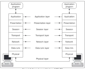
Communication between two computers is shown in the following figure:
Figure 1.3: Seven-layer architecture of ISO OSI
1.1.1 Physical Layer
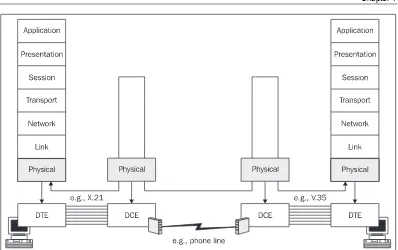
The physical layer is responsible for activating the physical circuit between the DataTerminal Equipment (DTE) and DataCircuit-terminatingEquipment (DCE), communicating through it, and then deactivating it. Additionally, the physical layer is also responsible for the
communication between DCEs (see Figure 1.3a). A computer or router can represent the DTE. The DCE, on the other hand, is usually represented by a modem or a multiplexer.
Chapter 1
Figure 1.3a: DTE and DCE
To put it differently, the physical layer describes the electric or optical signals used for
communicating between two computers. Physical circuits are created on the physical layer. Other appliances such as modems modulating a signal for a phone line are often put in the physical circuits created between two computers.
Physical layer protocols specify the following:
• Electrical signals (for example, +1V)
• Connector shapes (for example, V.35)
• Media type (twisted pair, coaxial cable, optical fiber, etc.)
• Modulation (for example, FM, PM, etc.)
• Coding (for example, RZ, NRZ, etc.)
• Synchronization (synchronous and asynchronous communication, time source, and so on)
1.1.2 Data Link Layer
As for serial links, the link layer provides data exchange between neighboring computers as well as data exchange between computers within a local network.
Introduction to Network Protocols
Figure 1.4: Data link packet or frame
A frame carries the destination link address, source link address, and other control information in the header. The trailer usually contains the checksum of the transported data. By using the checksum, we can find out whether the payload has been damaged during transfer. The network-layer packet is usually included in the payload.
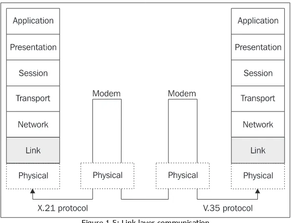
In Figure 1.3a, the link layer does not engage in a conversation between DTE and DCE (the link layer does not see the DCE). It is engaged, however, in the frame exchange between DTEs. (It relies on the physical layer to handle the DCE issue.)
The following figure illustrates that different protocols can be used for each end of the connection on the physical layer. In our case, one of the ends uses the X.21 protocol while the other end uses the V.35 protocol. This rule is valid not only for serial links, but also for local networks. In local networks, you are more likely to encounter more complicated setups in which a switch that converts the link frames of one link protocol into link frames of a second one (for example, Ethernet into FDDI) is inserted between the two ends of the connection. This obviously results in different protocols being used on the physical layer.
Figure 1.5: Link layer communication
A serial port or an Ethernet card can serve as a link interface. A link interface has a link address that is unique within a particular LocalAreaNetwork (LAN).
Chapter 1
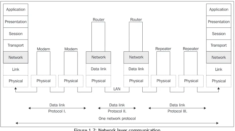
1.1.3 Network Layer
The network layer ensures the data transfer between two remote computers within a particular WideAreaNetwork (WAN). The basic unit of transfer is a datagram that is wrapped
(encapsulated) in a frame. The datagram is also composed of a header and data field. Trailers are not very common in network protocols.
Figure 1.6: Network packet and its insertion in the link frame
As shown in the figure above, the datagram header, together with data (network-layer payload), creates the payload or data field of the frame.
There is usually at least one router on WANs between two computers. The connection between two neighboring routers on the link layer is always direct. The router unpacks the datagram from a frame, only to wrap it again into a different frame (or, more generally, in a frame of different link protocol) before sending it to a different line. The network layer does not see the appliances on the physical and link layers (modems, repeaters, switches, etc.).
The network layer does not care about what kind of link protocols are used on route between the source and the destination.
Introduction to Network Protocols
A serial port or an Ethernet card can be used as a network interface. A network interface has a one or more unique address within a particular WAN.
1.1.4 Transport Layer
A network layer facilitates the connection between two remote computers. As far as the transport layer is concerned, it acts as if there were no modems, repeaters, bridges, or routers along the way. The transport layer relies completely on the services of lower layers. It also expects that the connection between two computers has been established, and it can therefore fully dedicate its efforts to the cooperation between two distant computers. Generally, the transport layer is responsible for communication between two applications running on different computers. There can be several transport connections between two computers at any given time (for example, one for a virtual terminal and another for email). On the network layer, the transport packets are directed based on the address of the computer (or its network interface). On the transport layer, individual applications are addressed. Applications use unique addresses within one computer, so the transport address is usually composed of both the network and transport addresses.
Figure 1.8: Transport layer connection
In this case, the basic transmission unit is the segment that is composed of a header and payload. The transport packet is transmitted within the payload of the network packet.
Figure 1.9: Inserting transport packets into network packets that are then inserted into link frames
Chapter 1
1.1.5 Session Layer
The session layer facilitates exchange of data between two applications. In other words, it serves as a checkpoint and is involved in synchronizing transactions, correctly closing files, and so on. Sharing a network disk is a good example of a session. The disk can be shared for a certain period of time, but the disk is not used for the entire time. When we need to work with a file on the network disk, a connection is established on the transport layer from the time when the file is opened to when it is closed. The session, however, exists on the session layer for the entire time the disk is being shared.
The basic unit is a session layer PDU (Protocol Data Unit), which is inserted in a segment. Other books often illustrate this with a figure of a session-layer PDU, composed of the session header and payload, being inserted in the segment. Starting with the session layer, however, this does not necessarily have to be the case. The session layer information can be transmitted inside the payload. This situation is even more noticeable if, for example, the presentation layer encrypts the data, and thus changes the whole content of the session-layer PDU.
1.1.6 Presentation Layer
The presentation layer is responsible for representing and securing data. The representation can differ on different computers. For example, it deals with the problem of whether the highest bit is in the byte on the right or on the left. By securing, we mean encrypting, ensuring data integrity, digital signing, and so forth.
1.1.7 Application Layer
The application layer defines the format in which the data should be received from or handed over to the applications. For example, the OSI Virtual Terminal protocol describes how data should be formatted as well as the dialogue used between the two ends of the connection.
Introduction to Network Protocols
14
1.2 TCP/IP
With a few exceptions, the TCP/IP family does not deal with the physical or link layers. In practice, Internet protocols often use protocols that adhere to the ISO OSI standards for the physical and link layers.
What is the correlation between the ISO OSI protocols and TCP/IP? Each group of protocols has its definition of its own layers as well as the protocols used on these layers. Generally speaking, ISO OSI protocols and TCP/IP are incompatible. In practice, ISO OSI-compliant communication appliances need to be used for transferring IP datagrams, or on the other hand, services based on ISO OSI need to be provided via the Internet.
1.2.1 Internet Protocol
InternetProtocol (IP) basically corresponds to the network layer. IP is used for transmitting IP datagrams between remote computers. Each IP datagram header contains the destination address, which is the complete routing information used for delivering the IP datagram to its destination. Therefore, the network can only transmit each datagram individually. IP datagrams of one session can be transmitted through different paths and can thus be received by the destination in a different order than they were sent.
Each network interface on the large Internet network has one or more IP address that is unique worldwide. (One network interface can have several IP addresses, but one IP address cannot be used by many network interfaces.) The Internet is composed of individual networks that are interconnected via routers. Routers are also referred to as gateways in old literature.
1.2.2 TCP and UDP
TCP and UDP correspond to the transportation layer. TCP transports data using TCP segments that are addressed to individual applications. UDP transports data using UDP datagrams. TCP and UDP arrange a connection between applications that run on remote computers. TCP and UDP can also facilitate communication between processes running on the same computer, but this is not very interesting for our purposes.
The difference between TCP and UDP is that TCP is a connection-oriented service—the destination confirms the data received. If some data (TCP segments) gets lost, the destination requests a retransmission of the lost data. UDP transports data using datagrams (the delivery is not guaranteed). In other words, the source party sends the datagram without worrying about whether it has been received. UDP is connectionless-oriented service.
The port is used as the address. To understand the difference between an IP address and port number, think of it as a mailing address. The IP address corresponds to the address of a house, while the port tells you the name of the person that should receive the letter.
Chapter 1
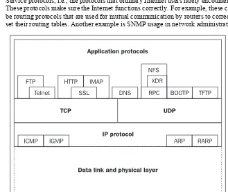
1.2.3 Application Protocols
Application protocols correspond to several ISO OSI layers. The session, presentation, and application ISO OSI layers are reduced to one TCP/IP application layer.
The absence of a presentation layer is made up for by introducing specialized presentation-application protocols such as SSL and S/MINE that specialize in securing data or the Virtual Terminal and ASN.1 protocols that are designed for presenting data. The Virtual Terminal protocol (not to be confused with the ISO OSI protocol of the same name) specifies the network data presentation for character-oriented network protocols (Telnet, FTP, SMTP, and, partly, HTTP). Similarly, ASN.1 is often used for binary-oriented network transport. ASN.1 (including BER or DER encoding) was initially used by SNMP, but today it is also used by S/MINE. There are many different application protocols. For practical purposes, they can be divided into two groups:
• User protocols utilized by user applications (HTTP, SMTP, Telnet, FTP, IMAP, PIP3, and so on).
• Service protocols, i.e., the protocols that ordinary Internet users rarely encounter. These protocols make sure the Internet functions correctly. For example, these could be routing protocols that are used for mutual communication by routers to correctly set their routing tables. Another example is SNMP usage in network administration.
Introduction to Network Protocols
1.3 Methods of Information Transmission
There are many different network protocols and several protocols can be available even on a single layer. Especially with lower-layer protocols, we distinguish between the types of transmission that they facilitate, whether they provide connection-oriented or connection-less services, if the protocol uses virtual circuits, and so on. We also distinguish between synchronous, packet, and asynchronous transmission.
1.3.1 Synchronous Transmission
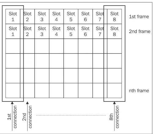
Synchronous transmission is needed when it is necessary to provide a stable (guaranteed) bandwidth, for example, in audio and video. If the source does not use the provided bandwidth it remains unused. Synchronous transmission uses frames that are of fixed length and are transmitted at constant speeds.
Figure 1.12: Frames divided into slots in synchronous transmission
In synchronous transmission, the guaranteed bandwidth is established by dividing the transmitted frames into slots (see Figure 1.12). One or more slots in any transmitted frame are reserved for a particular connection. Let's say that each frame has slot 1 reserved for our connection. Since the frames follow each other steadily in a network, our application has a guaranteed bandwidth consisting of the number of slot 1s that can be transmitted through the network in one second. The concept becomes even clearer if we draw several frames under each other, creating a 'super-frame' (see Figure 1.13). The slots located directly under each other belong to the same connection.
Figure 1.13: Super-frame
Chapter 1
Synchronous transmission is used to connect your company switchboard to the phone company exchange. In this case, we use an E1(or T1 in United States) link containing 32 slots of 64 Kbps each. A slot can be used for making a phone call. Therefore, in theory, 32 calls are guaranteed at the same time (although some slots are probably used for servicing).
The Internet does not use synchronous transmission, i.e., in general, does not guarantee bandwidth. Quality audio or video transmission on the Internet is usually achieved by over-dimensioning the transmission lines. Recently, there has been a steady increase in requests for audio and video transmission via the Internet, so more and more often we come across systems that guarantee bandwidth even on the Internet with the help of Quality of Service (QoS). In order for us to reach the expected results, however, all appliances on route from the source to the destination must support these services. Today, we are more likely to get involved with only those areas on the Internet that guarantee bandwidth such as within a particular Internet provider.
1.3.2 Packet Transmission
(From now onwards we will use the term packet to refer to 'packet', 'datagram', 'segment', 'protocol data unit'.) Packet transmission is especially valuable for transferring data. Packets usually carry data of variable size.
Figure 1.14: Packet data transmission
One packet always carries data of one particular application (of one connection). It is not possible to guarantee bandwidth, because the packets are of various lengths. On the other hand, we can use the bandwidth more effectively because if one application does not transmit data, then other applications can use the bandwidth instead.
1.3.3 Asynchronous Transmission
Asynchronous transmission is used in the ATM protocol. This transmission type combines features of packet transmission with features of synchronous transmission.
Figure 1.15: Asynchronous data transfer
Introduction to Network Protocols
1.4 Virtual Circuit
Some network protocols create virtual circuits in networks. A virtual circuit is conducted through the network and all packets of a particular connection go via the circuit. If the circuit gets interrupted anywhere, then the connection is interrupted, a new circuit is established, and data transmission continues.
Figure 1.16: Virtual circuit
In the figure above, a virtual circuit between nodes A and D is established via nodes B, F, and G. All packets must go through this circuit.
Datagrams can be transmitted via the virtual circuit in two ways:
• The circuit does not guarantee the datagram's delivery to its destination. (If network congestion occurs, the circuit can even throw the datagram away.) An example is the Frame Relay protocol.
• The virtual circuit can establish a connection and guarantee the data delivery, i.e., the data packets transmitted are numbered and the destination confirms their reception. If any data gets lost, a request to resend the data is made. For example, this mechanism is used in the X.25 protocol.
The advantage of virtual circuits is that they are first established (using signalization) and then the data is inserted only into the established circuit. Each packet does not have to carry the globally unique address of the destination (complete routing information) in its header. It only needs the circuit ID.
The virtual mechanism is not used on the Internet, which was primarily aimed for use by the U.S. Department of Defense, since the destruction of a node in the virtual circuit would result in the transmission being interrupted—a fact that the authors of TCP/IP did not like. For this reason, IP does not use virtual circuits. Each IP datagram carries a destination IP address (complete routing information) and is therefore transported independently. If a node is destroyed, only the IP
Chapter 1
datagrams currently being transmitted through that particular node are destroyed. The remaining datagrams are routed via different nodes.
Figure 1.17: IP does not use virtual circuits.
As the figure above shows, IP datagrams 1, 2, and 3 start from the node A to node B, but from this point, datagrams 1 and 3 are routed through a different path than datagram 2. The destination (node D) is then reached by each of them via a different path. Generally, IP datagrams may reach their destination in a different order than the order in which they were sent. So our IP datagrams could be received in the following order: 2, 1, and then 3.
In the Internet hierarchy, TCP—a higher-layer protocol that establishes a connection and guarantees the delivery of data—is used above the connectionless IP. If some of the data packets are lost, their retransmission is requested. If the data packets were lost due to the destruction of a node along the way and there is another routing possible within the network, then the transmission is automatically repeated using the other path.
Virtual circuits are divided into the following groups:
• Permanent (PermanentVirtualCircuit (PVC)), i.e., circuits permanently built by the network administrator.
Introduction to Network Protocols
20
2
Network Monitoring Tools
Network monitoring tools can be used to monitor data transfers on your network. Monitoring is a process of capturing link frames in the network and storing these frames in memory. Monitoring also includes viewing the contents of the individual captured frames.
Network monitoring tools are mostly used by network administrators to look for network configuration errors or monitor network workload. These tools are also an indispensable resource for programmers who develop network applications. To give you an example, let's say you have written a client/server application. You start the application and nothing happens—the client does not even connect to the server. At this point, you cannot be sure whether the problem lies with the client or the server. By capturing frames, however, you can establish that the client sent a data frame, but the server did not react and the fault is therefore likely on the server's side. Or you might notice that the data sent by the client is different from what you expected.
We will mainly use the two programs, Network Monitor and Ethereal, to demonstrate different network protocols. Both programs have a similar graphical user interface. A wide selection of similar programs is available in the market. The UNIX operating system offers the tcpdump command. As opposed to the programs mentioned above, tcpdump does not have a graphical user interface and is designed to be used mainly for scripts.
In addition to these tools, network monitoring hardware is also available. What are the advantages of hardware network monitors? These tools are particularly important for technical staff. Software monitors only display frames that are undamaged. It may be that a station has a damaged network interface card, which produces faulty frames. Software monitors have a difficult time recognizing these damaged stations. Moreover, Fiber Distributed Data Interface (FDDI) service frames are not displayed by software monitors.
Network Monitoring Tools
22
2.1 Packet Drivers
In order to keep track of incoming and outgoing packets, we have to insert a component between the network interface and the rest of the operating system. This component is able to track the passing packets or perhaps hand them over to other programs to be protocolled or displayed. This component is often called a packetdriver or packetfilter. In MS Windows NT (Windows 2000, XP etc.), the packet driver is called the Network Monitor Agent. The program that protocols or displays the packets captured by the packet driver, is the Network Monitor for Windows or the tcpdump command for UNIX.
The network interface cards of systems connected to the LAN listen to the traffic on the LAN, i.e., they read individual passing link frames. Link frames of protocols for local networks usually start with the destination link address, so if the station finds that the incoming frame is not addressed to itself, then it usually ignores the rest of the frame. In practice this means that the packet driver can only accept frames that are addressed to the station where the packet driver is running (and also the frames that this station sends onto the network). If this is not enough and you want to track all the traffic in your LAN segment, then you have to switch the network interface card into
promiscuous mode. In promiscuous mode, the network card reads all the frames and we can track all the traffic in your LAN segment. You can switch the network interface card into promiscuous mode using the Network Monitor program, which is a part of the SMS Server.
If the network interface card is not in promiscuous mode, you can see the frames sent out by your station and the ones that are addressed to it. These not only include frames that have one of your station's addresses, but also all broadcasts. You will also see all multicasts that your station accepts. This is a somewhat complex problem that is discussed in detail in Section 5.7. Another problem is keeping track of traffic on a switched Ethernet. If you want to track communication in LAN segments other than the one your PC connects to, you must keep in mind that the frames are usually not repeated in the segment where your PC is located. This can be solved by using a switch diagnostic output or by poisoning the ARP cache.
These days, ordinary repeaters are not used very frequently; almost everything is done with switches. So if you want to keep track of traffic on a station or a server, you need to get hold of an old repeater with at least three interfaces. One interface will be connected to a switch distribution, i.e., the repeater will be plugged into the interface into which the station was originally plugged, the second interface will be connected to the station we want to watch, and the third interface will be connected to a notebook with the relevant packet driver.
If you want to use Network Monitor, you must add the Network Monitor Agent to your network configuration.
In UNIX-type operating systems, the packet driver is usually added to the operating system kernel. For example, you add PACKETFILTER options into the configuration file of a kernel for UNIX True64. Then you create a new kernel. By using the pfconfig command, you can switch individual interfaces into promiscuous mode. You can use the pfstat command to examine the configuration of a particular interface.
Chapter 2
also acts as a UNIX packet driver. Ethereal is one of the several programs that uses this packet driver and thereby works on both Windows and UNIX.
2.2 MS Network Monitor
MS Network Monitor is supplied with certain Microsoft products (such as SMS Server). Installing the program on Windows NT must be done very carefully and exactly according to the
instructions in the guide. In the middle of the installation process, you will usually be asked to install Network Monitor Agent. If you do not follow the instructions exactly, the program will not function and will need to be reinstalled.
Starting with Windows 2000 and later, Network Monitor is supplied as a part of the server (Network Monitor Tools). On the other hand, Windows 2000 and XP restricts the use of the program. Therefore, we more often find Ethereal used in PCs.
The Network Monitor handles frame display well. Not only can it separate the header from the actual data, but it can also dissect individual items in the network protocol headers.
2.2.1 Frame Capturing
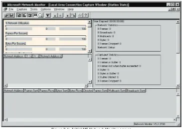
When you start Network Monitor, the window shown in Figure 2.1 pops up. Inside this window should be the Capture window. If this inner window does not open, then the Network Monitor or the Network Monitor Agent is not installed properly and needs to be reinstalled.
Network Monitoring Tools
First of all, you have to choose the appropriate network interface to use for frame capturing. This is done by choosing
24
Capture | Networks. There's also another interesting detail that we have to pay attention to. After looking at the following figure, in the left window we will choose the interface we want to sniff:
Figure 2.2: Selecting the network interface used for frame capturing
The issue here is the Windows 2000 architecture. It has an NDIS layer located above the network interface cards that ensures a standard communication between the operating system and network interface cards, although this only applies to LAN cards.
An NDISWAN driver (Ndiswan.sys) inserted between the serial lines ports, changes the communication format of the serial port into a format that adheres to the Ethernet protocol (in other words, into a form commonly processed by the NDIS layer). This has two practical results:
1. If you want to capture frames on a serial line, then you have to choose an interface with Dial-up Connection that is set to TRUE.
2. After you have captured the frames on the serial line, they have (for example, when establishing a connection through the PPP protocol) special link addresses inside the Ethernet frame:
o For the frame being sent, both the sender and receiver fields contain the
SEND string.
o For the frame being received, both fields will contain RECV.
It is important to not confuse this with the 'PPP over Ethernet' protocol that is supported by Microsoft Windows XP.
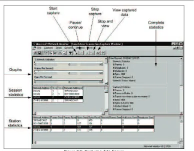
Now, we can start capturing frames by clicking Start capture (see Figure 2.3) or by choosing F10
Chapter 2
Figure 2.3: Capturing data frames
The window for capturing data frames consists of several smaller windows. The window on the top left contains graphs that describe:
• %Network Utilization, i.e., rate of the utilization of all network resources that are available for current capturing
• Frames Per Second, i.e., the number of frames that the network transfers each second
• Bytes Per Second, i.e., the number of bytes transported each second
• Broadcast Per Second, i.e., the number of broadcasts per second
• Multicast Per Second, i.e., the number of multicasts per second
The complete statistics window is on the top-right. The time that has elapsed from the beginning of capturing is shown on the first line. Each particular area of information has its own graph:
• Network Statistics shows the total number of frames that have gone through the LAN segment; it also shows how many of them were broadcast, etc.
Network Monitoring Tools
26
• Per Second Statistics shows the average statistical values per second.
• Network Card Statistics shows the network interface card's average connection speed. The session statistics window gives you statistical data for individual sessions. A session is an interval during which two stations exchange data. There is one line for each pair of stations. The numeric value shows the number of frames sent from one station to the other (or vice versa). Network Monitor displays session statistics for the first 100 unique network sessions that it detects. To reset statistics and view information about the next 100 detected unique network sessions, click Capture |Clear Statistics.
In addition to capturing frames, you can also choose Capture |Activation to prepare an action that can be automatically activated, like when a certain part of the buffer memory is exhausted. One interesting option is to activate whenever a frame containing a specified string in a particular position appears. The activation can also be triggered when a program starts up or when a file opens.
2.2.2 Viewing Captured Frames
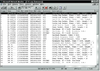
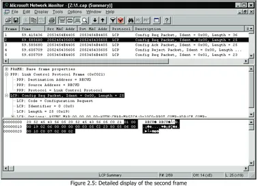
When you click Stop and View to switch to the mode for viewing captured frames, the following window with the captured frames appears:
Chapter 2
You can see your chosen frame in the captured frame display. To view detailed information of any frame, click it in the window as shown in the following figure:
Figure 2.5: Detailed display of the second frame
Detailed information appears in three frames of windows. The top window displays the captured frames, the middle window shows the details of the selected captured frame, and the bottom window shows the captured frame in hexadecimals and characters (dump format).
The middle window is the one we're most interested in. Figure 2.5 shows the link header followed by a network packet header. Anything from the transport header to the application layer can be displayed here. Even at the application layer, detailed information for many packets is provided as well.
Some header entries have a + sign in front of them. This tells you that detailed information can be obtained by clicking the + sign. We will therefore discuss the individual headers of all protocols described in this book.
The dissected frames can also be printed by selecting File|Print. The frame in Figure 2.5 is as follows:
+ Frame: Base frame properties PPP: Unknown Frame (0x0)
PPP: Destination Address = RECV_ PPP: Source Address = RECV_
PPP: Protocol = Link Control Protocol
Network Monitoring Tools
28
LCP: Identifier = 0 (0x0) LCP: Length = 25 (0x19)
LCP: Options: ASYNC.MAP:00 00 00 00-AUTH:CHAP-MAGIC#:0x10C0-PROT.COMP-ADR/CF.COMP-
(The Network Monitor version used in Windows 2000 Server has a drawback in that the statement is in UNICODE. This would not be an issue if there were two bytes containing a hexadecimal FF or FE at the beginning, which would signal to Windows that it is a UNICODE file. After adding these characters to the beginning by using the WinVi editor, the statement resulted in the form shown above.)
2.2.3 Filters for Displaying Captured Frames
The most common problem when using network monitor programs is finding the required frame often from huge numbers of frames. You can use filters to make the task easier. There are two kinds of filters:
• Frame capturing filters that are activated in Network Monitor before capturing starts (Capture|Filter or F8).
• Filters for displaying captured frames that are activated upon viewing frames. These filters let you display only selected captured frames (Display|Filter or F8).
Filters consist of logical conditions that are linked by the AND, OR, and NOT logical operators. A condition might involve:
• An address (for example, IP address in the case of IP protocol)
• A protocol, i.e., only frames with specified protocols will be shown (IP, HTTP, etc.)
• The value of a specific protocol's item, for example, the TCP port of the sender is 1345
2.3 Ethereal
Ethereal is an alternative to Network Monitor and can be used with Windows 2000 Professional or Windows XP. You can download the program at http://www.ethereal.com/. In addition to the graphical Ethereal program, the distribution also contains other utilities such as a command-line version called Tethereal.
Chapter 2
After you have successfully installed the packet driver, you can install and configure Ethereal. When you run the program, you are presented with the window shown in Figure 2.6, which is similar to the Network Monitor window shown in Figure 2.5. Choose Capture|Start to open a window where you can enter parameters for frame capturing. For example, by clicking Interface you can choose the network interface used to capture frames. Click OK to begin capturing. After the capturing has finished, you can view the individual captured frames in the same way as you would in Network Monitor.
Figure 2.6: Starting frame capturing in Ethereal
Ethereal can also open files with stored frames generated by various other programs, including Network Monitor.
Ethereal contains a range of interesting tools like the FollowTCPStream command, which is available in the Tools menu. By choosing this command, the contents of a particular TCP connection can be displayed in ASCII characters or in hexadecimals.
Network Monitoring Tools
Figure 2.7: TCP connection statements in Ethereal
The boxes in the figure above outline the user name anonymous and password [email protected]. If you had connected to a non-anonymous server, your real password would have been disclosed in this way.
2.4 Homework
You should now be ready to experiment with Network Monitor or Ethereal. It is recommended that you try to capture your own password as the first exercise. (The authors strongly discourage you from trying to capture somebody else's password—after all, this would not be possible without switching your network card into promiscuous mode or using switched Ethernet.) Try these two exercises:
Telnet
30
Chapter 2
HTTP
2. protocol: Find some HTTP server with basic authentication with username and password and sniff the communication of this server. The name and password form a part of each user's query. But since the HTTP header lines cannot contain any characters that are not a part of ASCII, the username and password are separated by a colon and the whole thing is coded in Base64 format. Decoding needs to be done either manually or using a suitable program. (This does not work with HTTPS protocol as passwords cannot be captured there, because the connection is encrypted.)
The header contains the following information: Authorization:Base64(username:password)
Or for firewall authorization:
Proxy-Authorization:Base64(username:password)
Where Base64() means that the Base64 argument is coded in seven-bit form.
If you do not feel like decoding Base64 by hand on a piece of paper, you can use programs such as the OpenSSL program with the enc–a–d parameters.
3
Physical Layer
Protocols of the physical layer are for the vast majority of users They are completely hidden protocols that describe signals on the connectors (commonly referred to as plugs) on the back part of the computer, to which a cable connecting the computer with the network is attached. Users tend to shift the responsibility to technical staff, whom they consider people "who take care of wires, by measuring something with a voltmeter." The situation today is completely different. A technician more or less administers software that controls all the mysterious boxes in locked rooms. This idea does not actually refer to the physical layer only, but encompasses the link layer as well. The users usually get involved only in the IP protocol (or network protocols), since in this protocol, they either see or donotsee servers or neighbors. In contrast, the physical and link layers only provide communication with some kind of a box halfway down to the server, the existence of which is usually not known to regular users.
Generally, we distinguish between two types of network: a LocalAreaNetwork (LAN) and a Wide AreaNetwork (WAN). Regarding the physical layer, for one group of protocols are LAN protocols, while another group are WAN. However, the currently popular ATM protocol eliminates the differences between LAN and WAN, and it not only uses new protocols, but is also able to use the current WAN lines, including their protocols (for example, T1 lines in America or E1 lines in Europe). In addition, the ATM emulates protocols for the LAN protocol as well.
LAN
The LAN is used by several stations to communicate mostly on a shared medium. Within one LAN, the same link protocol is used (for example, Ethernet). Today, however, the term LAN also covers the so-called extended LANs that are composed of individual LANs. The extended LANs are created by connecting individual LANs via switches. Switches often have interfaces for various types of link protocols and are able to convert frames of one link protocol into frames of a different link protocol. An individual LAN composed of just two items, with one of them being the switch, is increasingly common.
Physical Layer
34
The transfer rate on today's LANs ranges from 10 Mbps to 10 Gbps.
WAN
Wide Area Networks cover a wide variety of situations, ranging from connecting a home PC to the Internet via a serial asynchronous line at rates in Kbps to intercontinental lines via underwater cables or satellite connection in tens of Gbps.
PAN
A Personal Area Network is used to exchange data between appliances (such as telephones, cell phones, and Personal Digital Assistants) within the range of a person; typically within the range of 10 meters. The most often used protocols for PAN networks are Bluetooth and WiFi (IEEE 802.11).
MAN
A Metropolitan Area Network is used to exchange data within some municipality or a group of them. MAN can use various protocols, but probably the most typical is using cable television cabling.
3.1 Serial Line
A PC has connectors for the COM1 and COM2 serial interfaces usually on the back. COM1 is commonly used for a mouse; hence after the serial line has been connected to our PC, only COM2 is left. The serial interface is usually used for connecting the modem.
Serial PC outputs use signals specified by the ITU-T V.24 standard (corresponding to the US standard—RS-232). It is an interface for serial asynchronous arrhythmic data transport. It is usually used for rates up to 64 Kbps although, you are most likely to connect your modem at home using 115,200 bps, and surprisingly, it is going to work well.
3.1.1 Serial and Parallel Data Transport
Serial transmission means that there is only one pair of wires (or one wire and a shared ground for asymmetric interfaces) for transporting information from the sender to the receiver. Therefore, the individual bits of every single character are transported following each other, i.e., serially. Parallel transmission uses eight wires (or multiples of eight) for transporting a group of bits. In other words, all bits of the character being transported can be transported at the same time, i.e., in parallel. Parallel transmission is used especially in (internal) computer buses and also for
communicating with a parallel printer. There are also modems using a parallel interface.
3.1.2 Symmetrical and Asymmetrical Signals
There are at least two signals used with serial interfaces: data reception and data transmission. If two wires carry each signal, then it is a symmetrical or differential signal. Symmetrical signals for data transfer are used, for example, by the V.35 and X.21 interfaces.