Ian Gibson · David Rosen Brent Stucker
Additive
Manufacturing Technologies
3D Printing, Rapid Prototyping, and Direct Digital Manufacturing
Second Edition
Additive Manufacturing Technologies
Ian Gibson • David Rosen • Brent Stucker
Additive Manufacturing Technologies
3D Printing, Rapid Prototyping, and Direct Digital Manufacturing
Second Edition
School of Engineering Deakin University Victoria, Australia
George W. Woodruff School of Mechanical Engineering
Georgia Institute of Technology Atlanta, GA USA
Brent Stucker
Department of Industrial Engineering, J B Speed University of Louisville
Louisville, KY USA
ISBN 978-1-4939-2112-6 ISBN 978-1-4939-2113-3 (eBook) DOI 10.1007/978-1-4939-2113-3
Springer New York Heidelberg Dordrecht London
Library of Congress Control Number: 2014953293
#Springer Science+Business Media New York 2010, 2015
This work is subject to copyright. All rights are reserved by the Publisher, whether the whole or part of the material is concerned, specifically the rights of translation, reprinting, reuse of illustrations, recitation, broadcasting, reproduction on microfilms or in any other physical way, and transmission or information storage and retrieval, electronic adaptation, computer software, or by similar or dissimilar methodology now known or hereafter developed. Exempted from this legal reservation are brief excerpts in connection with reviews or scholarly analysis or material supplied specifically for the purpose of being entered and executed on a computer system, for exclusive use by the purchaser of the work. Duplication of this publication or parts thereof is permitted only under the provisions of the Copyright Law of the Publisher’s location, in its current version, and permission for use must always be obtained from Springer. Permissions for use may be obtained through RightsLink at the Copyright Clearance Center.
Violations are liable to prosecution under the respective Copyright Law.
The use of general descriptive names, registered names, trademarks, service marks, etc. in this publication does not imply, even in the absence of a specific statement, that such names are exempt from the relevant protective laws and regulations and therefore free for general use.
While the advice and information in this book are believed to be true and accurate at the date of publication, neither the authors nor the editors nor the publisher can accept any legal responsibility for any errors or omissions that may be made. The publisher makes no warranty, express or implied, with respect to the material contained herein.
Printed on acid-free paper
Springer is part of Springer Science+Business Media (www.springer.com)
Preface
Thank you for taking the time to read this book on Additive Manufacturing (AM).
We hope you benefit from the time and effort it has taken putting it together and that you think it was a worthwhile undertaking. It all started as a discussion at a conference in Portugal when we realized that we were putting together books with similar aims and objectives. Since we are friends as well as colleagues, it seemed sensible that we join forces rather than compete; sharing the load and playing to each other’s strengths undoubtedly means a better all-round effort and result.
We wrote this book because we have all been working in the field of AM for many years. Although none of us like to be called “old,” we do seem to have 60 years of experience, collectively, and have each established reputations as educators and researchers in this field. We have each seen the technologies described in this book take shape and develop into serious commercial tools, with tens of thousands of users and many millions of parts being made by AM machines each year. AM is now being incorporated into curricula in many schools, polytechnics, and universities around the world. More and more students are becoming aware of these technologies and yet, as we saw it, there was no single text adequate for such curricula. We believe that the first edition of this book provided such a text, and based upon the updated information in this 2nd edition, we hope we’ve improved upon that start.
Additive Manufacturing is defined by a range of technologies that are capable of translating virtual solid model data into physical models in a quick and easy process. The data are broken down into a series of 2D cross-sections of a finite thickness. These cross-sections are fed into AM machines so that they can be combined, adding them together in a layer-by-layer sequence to form the physical part. The geometry of the part is therefore clearly reproduced in the AM machine without having to adjust for manufacturing processes, like attention to tooling, undercuts, draft angles, or other features. We can say therefore that the AM machine is a What You See Is What You Build (WYSIWYB) process that is particularly valuable the more complex the geometry is. This basic principle drives nearly all AM machines, with variations in each technology in terms of the techniques used for creating layers and in bonding them together. Further variations
v
include speed, layer thickness, range of materials, accuracy, and of course cost.
With so many variables, it is clear to see why this book must be so long and detailed. Having said that, we still feel there is much more we could have written about.
The first three chapters of this book provide a basic overview of AM processes.
Without fully describing each technology, we provide an appreciation for why AM is so important to many branches of industry. We outline the rapid development of this technology from humble beginnings that showed promise but still requiring much development, to one that is now maturing and showing real benefit to product development organizations. In reading these chapters, we hope you can learn the basics of how AM works.
The next nine chapters (Chaps.4–12) take each group of technologies in turn and describe them in detail. The fundamentals of each technology are dealt with in terms of the basic process, whether it involves photopolymer curing, sintering, melting, etc., so that the reader can appreciate what is needed in order to under- stand, develop, and optimize each technology. Most technologies discussed in this book have been commercialized by at least one company; and these machines are described along with discussion on how to get the best out of them. The last chapter in this group focused on inexpensive processes and machines, which overlaps some of the material in earlier chapters, but we felt that the exponentially increasing interest in these low-cost machines justified the special treatment.
The final chapters deal with how to apply AM technology in different settings.
Firstly, we look at selection methods for sorting through the many options concerning the type of machine you should buy in relation to your application and provide guidelines on how to select the right technology for your purpose.
Since all AM machines depend on input from 3D CAD software, we go on to discuss how this process takes place. We follow this with a discussion of post- processing methods and technologies so that if your selected machine and material cannot produce exactly what you want, you have the means for improving the part’s properties and appearance. A chapter on software issues in AM completes this group of chapters.
AM technologies have improved to the extent that many manufacturers are using AM machine output for end-product use. Called Direct Digital Manufacturing, this opens the door to many exciting and novel applications considered impossible, infeasible, or uneconomic in the past. We can now consider the possibility of mass customization, where a product can be produced according to the tastes of an individual consumer but at a cost-effective price. Then, we look at how the use of this technology has affected the design process considering how we might improve our designs because of the WYSIWYB approach. This moves us on nicely to the subjects of applications of AM, including tooling and products in the medical, aerospace, and automotive industries. We complete the book with a chapter on the business, or enterprise-level, aspects of AM, investigating how these systems
enable creative businesses and entrepreneurs to invent new products, and where AM will likely develop in the future.
This book is primarily aimed at students and educators studying Additive Manufacturing, either as a self-contained course or as a module within a larger course on manufacturing technology. There is sufficient depth for an undergraduate or graduate-level course, with many references to point the student further along the path. Each chapter also has a number of exercise questions designed to test the reader’s knowledge and to expand their thinking. A companion instructor’s guide is being developed as part of the 2nd edition to include additional exercises and their solutions, to aid educators. Researchers into AM may also find this text useful in helping them understand the state of the art and the opportunities for further research.
We have made a wide range of changes in moving from the first edition, completed in 2009, to this new edition. As well as bringing everything as up to date as is possible in this rapidly changing field, we have added in a number of new sections and chapters. The chapter on medical applications has been extended to include discussion on automotive and aerospace. There is a new chapter on rapid tooling as well as one that discusses the recent movements in the low-cost AM sector. We have inserted a range of recent technological innovations, including discussion on the new Additive Manufacturing File Format as well as other inclusions surrounding the standardization of AM with ASTM and ISO. We have also updated the terminology in the text to conform to terminology developed by the ASTM F42 committee, which has also been adopted as an ISO international standard. In this 2nd edition we have edited the text to, as much as possible, remove references to company-specific technologies and instead focus more on technolog- ical principles and general understanding. We split the original chapter on printing processes into two chapters on material jetting and on binder jetting to reflect the standard terminology and the evolution of these processes in different directions.
As a result of these many additions and changes, we feel that this edition is now significantly more comprehensive than the first one.
Although we have worked hard to make this book as comprehensive as possible, we recognize that a book about such rapidly changing technology will not be up-to- date for very long. With this in mind, and to help educators and students better utilize this book, we will update our course website athttp://www.springer.com/
978-1-4419-1119-3, with additional homework exercises and other aids for educators. If you have comments, questions, or suggestions for improvement, they are welcome. We anticipate updating this book in the future, and we look forward to hearing how you have used these materials and how we might improve this book.
Preface vii
As mentioned earlier, each author is an established expert in Additive Manufacturing with many years of research experience. In addition, in many ways, this book is only possible due to the many students and colleagues with whom we have collaborated over the years. To introduce you to the authors and some of the others who have made this book possible, we will end this preface with brief author biographies and acknowledgements.
Singapore, Singapore Ian Gibson
Atlanta, GA, USA David Rosen
Louisville, KY, USA Brent Stucker
Acknowledgements
Dr. Brent Stucker thanks Utah State and VTT Technical Research Center of Finland, which provided time to work on the first edition of this book while on sabbatical in Helsinki; and more recently the University of Louisville for providing the academic freedom and environment needed to complete the 2nd edition.
Additionally, much of this book would not have been possible without the many graduate students and postdoctoral researchers who have worked with Dr. Stucker over the years. In particular, he would like to thank Dr. G.D. Janaki Ram of the Indian Institute of Technology Madras, whose coauthoring of the “Layer-Based Additive Manufacturing Technologies” chapter in theCRC Materials Processing Handbookhelped lead to the organization of this book. Additionally, the following students’ work led to one or more things mentioned in this book and in the accompanying solution manual: Muni Malhotra, Xiuzhi Qu, Carson Esplin, Adam Smith, Joshua George, Christopher Robinson, Yanzhe Yang, Matthew Swank, John Obielodan, Kai Zeng, Haijun Gong, Xiaodong Xing, Hengfeng Gu, Md. Anam, Nachiket Patil, and Deepankar Pal. Special thanks are due to Dr. Stucker’s wife Gail, and their children: Tristie, Andrew, Megan, and Emma, who patiently supported many days and evenings on this book.
Prof. David W. Rosen acknowledges support from Georgia Tech and the many graduate students and postdocs who contributed technically to the content in this book. In particular, he thanks Drs. Fei Ding, Amit Jariwala, Scott Johnston, Ameya Limaye, J. Mark Meacham, Benay Sager, L. Angela Tse, Hongqing Wang, Chris Williams, Yong Yang, and Wenchao Zhou, as well as Lauren Margolin and Xiayun Zhao. A special thanks goes out to his wife Joan and children Erik and Krista for their patience while he worked on this book.
Prof. Ian Gibson would like to acknowledge the support of Deakin University in providing sufficient time for him to work on this book. L.K. Anand also helped in preparing many of the drawings and images for his chapters. Finally, he wishes to thank his lovely wife, Lina, for her patience, love, and understanding during the long hours preparing the material and writing the chapters. He also dedicates this book to his late father, Robert Ervin Gibson, and hopes he would be proud of this wonderful achievement.
ix
1 Introduction and Basic Principles. . . 1
1.1 What Is Additive Manufacturing? . . . 1
1.2 What Are AM Parts Used for? . . . 3
1.3 The Generic AM Process . . . 4
1.3.1 Step 1: CAD . . . 4
1.3.2 Step 2: Conversion to STL . . . 4
1.3.3 Step 3: Transfer to AM Machine and STL File Manipulation . . . 5
1.3.4 Step 4: Machine Setup . . . 5
1.3.5 Step 5: Build . . . 5
1.3.6 Step 6: Removal . . . 6
1.3.7 Step 7: Post-processing . . . 6
1.3.8 Step 8: Application . . . 6
1.4 Why Use the Term Additive Manufacturing? . . . 7
1.4.1 Automated Fabrication (Autofab) . . . 7
1.4.2 Freeform Fabrication or Solid Freeform Fabrication . . . 7
1.4.3 Additive Manufacturing or Layer-Based Manufacturing . . . 7
1.4.4 Stereolithography or 3D Printing . . . 8
1.4.5 Rapid Prototyping . . . 8
1.5 The Benefits of AM . . . 9
1.6 Distinction Between AM and CNC Machining . . . 10
1.6.1 Material . . . 10
1.6.2 Speed . . . 10
1.6.3 Complexity . . . 11
1.6.4 Accuracy . . . 11
1.6.5 Geometry . . . 12
1.6.6 Programming . . . 12
1.7 Example AM Parts . . . 12
1.8 Other Related Technologies . . . 14
1.8.1 Reverse Engineering Technology . . . 14
1.8.2 Computer-Aided Engineering . . . 15 xi
1.8.3 Haptic-Based CAD . . . 16
1.9 About this Book . . . 17
1.10 Exercises . . . 17
References . . . 18
2 Development of Additive Manufacturing Technology. . . 19
2.1 Introduction . . . 19
2.2 Computers . . . 20
2.3 Computer-Aided Design Technology . . . 22
2.4 Other Associated Technologies . . . 26
2.4.1 Lasers . . . 26
2.4.2 Printing Technologies . . . 26
2.4.3 Programmable Logic Controllers . . . 27
2.4.4 Materials . . . 27
2.4.5 Computer Numerically Controlled Machining . . . 28
2.5 The Use of Layers . . . 28
2.6 Classification of AM Processes . . . 30
2.6.1 Liquid Polymer Systems . . . 31
2.6.2 Discrete Particle Systems . . . 32
2.6.3 Molten Material Systems . . . 33
2.6.4 Solid Sheet Systems . . . 34
2.6.5 New AM Classification Schemes . . . 34
2.7 Metal Systems . . . 35
2.8 Hybrid Systems . . . 36
2.9 Milestones in AM Development . . . 37
2.10 AM Around the World . . . 39
2.11 The Future? Rapid Prototyping Develops into Direct Digital Manufacturing . . . 40
2.12 Exercises . . . 41
References . . . 41
3 Generalized Additive Manufacturing Process Chain. . . 43
3.1 Introduction . . . 43
3.2 The Eight Steps in Additive Manufacture . . . 44
3.2.1 Step 1: Conceptualization and CAD . . . 44
3.2.2 Step 2: Conversion to STL/AMF . . . 45
3.2.3 Step 3: Transfer to AM Machine and STL File Manipulation . . . 47
3.2.4 Step 4: Machine Setup . . . 47
3.2.5 Step 5: Build . . . 48
3.2.6 Step 6: Removal and Cleanup . . . 48
3.2.7 Step 7: Post-Processing . . . 49
3.2.8 Step 8: Application . . . 49
3.3 Variations from One AM Machine to Another . . . 50
3.3.1 Photopolymer-Based Systems . . . 51
xii Contents
3.3.2 Powder-Based Systems . . . 51
3.3.3 Molten Material Systems . . . 51
3.3.4 Solid Sheets . . . 52
3.4 Metal Systems . . . 52
3.4.1 The Use of Substrates . . . 53
3.4.2 Energy Density . . . 53
3.4.3 Weight . . . 53
3.4.4 Accuracy . . . 53
3.4.5 Speed . . . 54
3.5 Maintenance of Equipment . . . 54
3.6 Materials Handling Issues . . . 54
3.7 Design for AM . . . 55
3.7.1 Part Orientation . . . 55
3.7.2 Removal of Supports . . . 56
3.7.3 Hollowing Out Parts . . . 57
3.7.4 Inclusion of Undercuts and Other Manufacturing Constraining Features . . . 57
3.7.5 Interlocking Features . . . 57
3.7.6 Reduction of Part Count in an Assembly . . . 58
3.7.7 Identification Markings/Numbers . . . 58
3.8 Application Areas That Don’t Involve Conventional CAD Modeling . . . 59
3.8.1 Medical Modeling . . . 59
3.8.2 Reverse Engineering Data . . . 59
3.8.3 Architectural Modeling . . . 60
3.9 Further Discussion . . . 60
3.9.1 Exercises . . . 61
References . . . 61
4 Vat Photopolymerization Processes. . . 63
4.1 Introduction . . . 63
4.2 Vat Photopolymerization Materials . . . 65
4.2.1 UV-Curable Photopolymers . . . 66
4.2.2 Overview of Photopolymer Chemistry . . . 67
4.2.3 Resin Formulations and Reaction Mechanisms . . . 70
4.3 Reaction Rates . . . 73
4.4 Laser Scan Vat Photopolymerization . . . 74
4.5 Photopolymerization Process Modeling . . . 74
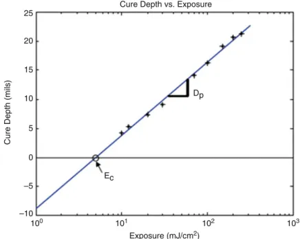
4.5.1 Irradiance and Exposure . . . 75
4.5.2 Laser–Resin Interaction . . . 78
4.5.3 Photospeed . . . 80
4.5.4 Time Scales . . . 81
4.6 Vector Scan VP Machines . . . 82
4.7 Scan Patterns . . . 84
4.7.1 Layer-Based Build Phenomena and Errors . . . 84
4.7.2 WEAVE . . . 86
4.7.3 STAR-WEAVE . . . 88
4.7.4 ACES Scan Pattern . . . 90
4.8 Vector Scan Micro-Vat Photopolymerization . . . 94
4.9 Mask Projection VP Technologies and Processes . . . 95
4.9.1 Mask Projection VP Technology . . . 95
4.9.2 Commercial MPVP Systems . . . 96
4.9.3 MPVP Modeling . . . 98
4.10 Two-Photon Vat Photopolymerization . . . 99
4.11 Process Benefits and Drawbacks . . . 101
4.12 Summary . . . 102
4.13 Exercises . . . 102
References . . . 103
5 Powder Bed Fusion Processes. . . 107
5.1 Introduction . . . 107
5.2 Materials . . . 109
5.2.1 Polymers and Composites . . . 109
5.2.2 Metals and Composites . . . 110
5.2.3 Ceramics and Ceramic Composites . . . 112
5.3 Powder Fusion Mechanisms . . . 112
5.3.1 Solid-State Sintering . . . 112
5.3.2 Chemically Induced Sintering . . . 115
5.3.3 LPS and Partial Melting . . . 116
5.3.4 Full Melting . . . 120
5.3.5 Part Fabrication . . . 121
5.4 Process Parameters and Modeling . . . 122
5.4.1 Process Parameters . . . 123
5.4.2 Applied Energy Correlations and Scan Patterns . . . . 125
5.5 Powder Handling . . . 127
5.5.1 Powder Handling Challenges . . . 127
5.5.2 Powder Handling Systems . . . 128
5.5.3 Powder Recycling . . . 129
5.6 PBF Process Variants and Commercial Machines . . . 131
5.6.1 Polymer Laser Sintering . . . 131
5.6.2 Laser-Based Systems for Metals and Ceramics . . . 134
5.6.3 Electron Beam Melting . . . 136
5.6.4 Line-Wise and Layer-Wise PBF Processes for Polymers . . . 140
5.7 Process Benefits and Drawbacks . . . 143
5.8 Conclusions . . . 144
5.9 Exercises . . . 144
References . . . 145
xiv Contents
6 Extrusion-Based Systems. . . 147
6.1 Introduction . . . 147
6.2 Basic Principles . . . 148
6.2.1 Material Loading . . . 149
6.2.2 Liquification . . . 149
6.2.3 Extrusion . . . 149
6.2.4 Solidification . . . 153
6.2.5 Positional Control . . . 154
6.2.6 Bonding . . . 155
6.2.7 Support Generation . . . 156
6.3 Plotting and Path Control . . . 157
6.4 Fused Deposition Modeling from Stratasys . . . 160
6.4.1 FDM Machine Types . . . 161
6.5 Materials . . . 163
6.6 Limitations of FDM . . . 164
6.7 Bioextrusion . . . 166
6.7.1 Gel Formation . . . 166
6.7.2 Melt Extrusion . . . 166
6.7.3 Scaffold Architectures . . . 168
6.8 Other Systems . . . 168
6.8.1 Contour Crafting . . . 169
6.8.2 Nonplanar Systems . . . 169
6.8.3 FDM of Ceramics . . . 171
6.8.4 Reprap and Fab@home . . . 171
6.9 Exercises . . . 172
References . . . 173
7 Material Jetting. . . 175
7.1 Evolution of Printing as an Additive Manufacturing Process . . . 175
7.2 Materials for Material Jetting . . . 176
7.2.1 Polymers . . . 177
7.2.2 Ceramics . . . 180
7.2.3 Metals . . . 181
7.2.4 Solution- and Dispersion-Based Deposition . . . 183
7.3 Material Processing Fundamentals . . . 184
7.3.1 Technical Challenges of MJ . . . 184
7.3.2 Droplet Formation Technologies . . . 186
7.3.3 Continuous Mode . . . 187
7.3.4 DOD Mode . . . 188
7.3.5 Other Droplet Formation Methods . . . 190
7.4 MJ Process Modeling . . . 191
7.5 Material Jetting Machines . . . 195
7.6 Process Benefits and Drawbacks . . . 198
7.7 Summary . . . 198
7.8 Exercises . . . 199
References . . . 200
8 Binder Jetting. . . 205
8.1 Introduction . . . 205
8.2 Materials . . . 207
8.2.1 Commercially Available Materials . . . 207
8.2.2 Ceramic Materials in Research . . . 208
8.3 Process Variations . . . 210
8.4 BJ Machines . . . 212
8.5 Process Benefits and Drawbacks . . . 216
8.6 Summary . . . 217
8.7 Exercises . . . 217
References . . . 218
9 Sheet Lamination Processes. . . 219
9.1 Introduction . . . 219
9.1.1 Gluing or Adhesive Bonding . . . 219
9.1.2 Bond-Then-Form Processes . . . 220
9.1.3 Form-Then-Bond Processes . . . 222
9.2 Materials . . . 224
9.3 Material Processing Fundamentals . . . 225
9.3.1 Thermal Bonding . . . 226
9.3.2 Sheet Metal Clamping . . . 227
9.4 Ultrasonic Additive Manufacturing . . . 228
9.4.1 UAM Bond Quality . . . 229
9.4.2 Ultrasonic Metal Welding Process Fundamentals . . . 230
9.4.3 UAM Process Parameters and Process Optimization . . . 233
9.4.4 Microstructures and Mechanical Properties of UAM Parts . . . 235
9.4.5 UAM Applications . . . 239
9.5 Conclusions . . . 242
9.6 Exercises . . . 243
References . . . 243
10 Directed Energy Deposition Processes. . . 245
10.1 Introduction . . . 245
10.2 General DED Process Description . . . 247
10.3 Material Delivery . . . 249
10.3.1 Powder Feeding . . . 249
10.3.2 Wire Feeding . . . 251
10.4 DED Systems . . . 252
10.4.1 Laser Based Metal Deposition Processes . . . 252
10.4.2 Electron Beam Based Metal Deposition Processes . . . 256
10.4.3 Other DED Processes . . . 257
10.5 Process Parameters . . . 257
10.6 Typical Materials and Microstructure . . . 258
xvi Contents
10.7 Processing–Structure–Properties Relationships . . . 261
10.8 DED Benefits and Drawbacks . . . 266
10.9 Exercises . . . 267
References . . . 268
11 Direct Write Technologies. . . 269
11.1 Direct Write Technologies . . . 269
11.2 Background . . . 269
11.3 Ink-Based DW . . . 270
11.3.1 Nozzle Dispensing Processes . . . 271
11.3.2 Quill-Type Processes . . . 273
11.3.3 Inkjet Printing Processes . . . 275
11.3.4 Aerosol DW . . . 276
11.4 Laser Transfer DW . . . 277
11.5 Thermal Spray DW . . . 280
11.6 Beam Deposition DW . . . 282
11.6.1 Laser CVD . . . 282
11.6.2 Focused Ion Beam CVD . . . 284
11.6.3 Electron Beam CVD . . . 284
11.7 Liquid-Phase Direct Deposition . . . 285
11.8 Beam Tracing Approaches to Additive/Subtractive DW . . . 286
11.8.1 Electron Beam Tracing . . . 286
11.8.2 Focused Ion Beam Tracing . . . 287
11.8.3 Laser Beam Tracing . . . 287
11.9 Hybrid Technologies . . . 287
11.10 Applications of Direct Write Technologies . . . 288
11.10.1 Exercises . . . 290
References . . . 290
12 The Impact of Low-Cost AM Systems. . . 293
12.1 Introduction . . . 293
12.2 Intellectual Property . . . 294
12.3 Disruptive Innovation . . . 296
12.3.1 Disruptive Business Opportunities . . . 296
12.3.2 Media Attention . . . 297
12.4 The Maker Movement . . . 299
12.5 The Future of Low-Cost AM . . . 301
12.6 Exercises . . . 301
References . . . 301
13 Guidelines for Process Selection. . . 303
13.1 Introduction . . . 303
13.2 Selection Methods for a Part . . . 304
13.2.1 Decision Theory . . . 304
13.2.2 Approaches to Determining Feasibility . . . 305
13.2.3 Approaches to Selection . . . 307
13.2.4 Selection Example . . . 310
13.3 Challenges of Selection . . . 312
13.4 Example System for Preliminary Selection . . . 316
13.5 Production Planning and Control . . . 321
13.5.1 Production Planning . . . 322
13.5.2 Pre-processing . . . 323
13.5.3 Part Build . . . 323
13.5.4 Post-processing . . . 324
13.5.5 Summary . . . 324
13.6 Open Problems . . . 325
13.7 Exercises . . . 326
References . . . 326
14 Post-processing. . . 329
14.1 Introduction . . . 329
14.2 Support Material Removal . . . 329
14.2.1 Natural Support Post-processing . . . 330
14.2.2 Synthetic Support Removal . . . 331
14.3 Surface Texture Improvements . . . 334
14.4 Accuracy Improvements . . . 334
14.4.1 Sources of Inaccuracy . . . 335
14.4.2 Model Pre-processing to Compensate for Inaccuracy . . . 335
14.4.3 Machining Strategy . . . 337
14.5 Aesthetic Improvements . . . 341
14.6 Preparation for Use as a Pattern . . . 342
14.6.1 Investment Casting Patterns . . . 342
14.6.2 Sand Casting Patterns . . . 343
14.6.3 Other Pattern Replication Methods . . . 344
14.7 Property Enhancements Using Non-thermal Techniques . . . 345
14.8 Property Enhancements Using Thermal Techniques . . . 346
14.9 Conclusions . . . 349
14.10 Exercises . . . 349
References . . . 350
15 Software Issues for Additive Manufacturing. . . 351
15.1 Introduction . . . 351
15.2 Preparation of CAD Models: The STL File . . . 352
15.2.1 STL File Format, Binary/ASCII . . . 352
15.2.2 Creating STL Files from a CAD System . . . 354
15.2.3 Calculation of Each Slice Profile . . . 355
15.2.4 Technology-Specific Elements . . . 359
15.3 Problems with STL Files . . . 361
15.4 STL File Manipulation . . . 364
15.4.1 Viewers . . . 365
15.4.2 STL Manipulation on the AM Machine . . . 365
xviii Contents
15.5 Beyond the STL File . . . 367
15.5.1 Direct Slicing of the CAD Model . . . 367
15.5.2 Color Models . . . 368
15.5.3 Multiple Materials . . . 368
15.5.4 Use of STL for Machining . . . 368
15.6 Additional Software to Assist AM . . . 369
15.6.1 Survey of Software Functions . . . 370
15.6.2 AM Process Simulations Using Finite Element Analysis . . . 371
15.7 The Additive Manufacturing File Format . . . 372
15.8 Exercises . . . 373
References . . . 374
16 Direct Digital Manufacturing. . . 375
16.1 Align Technology . . . 375
16.2 Siemens and Phonak . . . 377
16.3 Custom Footwear and Other DDM Examples . . . 380
16.4 DDM Drivers . . . 383
16.5 Manufacturing Versus Prototyping . . . 385
16.6 Cost Estimation . . . 387
16.6.1 Cost Model . . . 387
16.6.2 Build Time Model . . . 389
16.6.3 Laser Scanning Vat Photopolymerization Example . . . 392
16.7 Life-Cycle Costing . . . 393
16.8 Future of DDM . . . 395
16.9 Exercises . . . 396
References . . . 397
17 Design for Additive Manufacturing. . . 399
17.1 Motivation . . . 400
17.2 Design for Manufacturing and Assembly . . . 401
17.3 AM Unique Capabilities . . . 404
17.3.1 Shape Complexity . . . 404
17.3.2 Hierarchical Complexity . . . 405
17.3.3 Functional Complexity . . . 407
17.3.4 Material Complexity . . . 409
17.4 Core DFAM Concepts and Objectives . . . 411
17.4.1 Complex Geometry . . . 411
17.4.2 Integrated Assemblies . . . 412
17.4.3 Customized Geometry . . . 412
17.4.4 Multifunctional Designs . . . 412
17.4.5 Elimination of Conventional DFM Constraints . . . 413
17.5 Exploring Design Freedoms . . . 413
17.5.1 Part Consolidation and Redesign . . . 414
17.5.2 Hierarchical Structures . . . 415
17.5.3 Industrial Design Applications . . . 417
17.6 CAD Tools for AM . . . 418
17.6.1 Challenges for CAD . . . 418
17.6.2 Solid-Modeling CAD Systems . . . 420
17.6.3 Promising CAD Technologies . . . 422
17.7 Synthesis Methods . . . 426
17.7.1 Theoretically Optimal Lightweight Structures . . . 426
17.7.2 Optimization Methods . . . 427
17.7.3 Topology Optimization . . . 428
17.8 Summary . . . 433
17.9 Exercises . . . 434
References . . . 434
18 Rapid Tooling. . . 437
18.1 Introduction . . . 437
18.2 Direct AM Production of Injection Molding Inserts . . . 439
18.3 EDM Electrodes . . . 443
18.4 Investment Casting . . . 444
18.5 Other Systems . . . 445
18.5.1 Vacuum Forming Tools . . . 445
18.5.2 Paper Pulp Molding Tools . . . 446
18.5.3 Formwork for Composite Manufacture . . . 446
18.5.4 Assembly Tools and Metrology Registration Rigs . . . 446
18.6 Exercises . . . 448
References . . . 448
19 Applications for Additive Manufacture. . . 451
19.1 Introduction . . . 451
19.2 Historical Developments . . . 452
19.2.1 Value of Physical Models . . . 453
19.2.2 Functional Testing . . . 453
19.2.3 Rapid Tooling . . . 454
19.3 The Use of AM to Support Medical Applications . . . 455
19.3.1 Surgical and Diagnostic Aids . . . 457
19.3.2 Prosthetics Development . . . 458
19.3.3 Manufacturing . . . 460
19.3.4 Tissue Engineering and Organ Printing . . . 460
19.4 Software Support for Medical Applications . . . 461
xx Contents
19.5 Limitations of AM for Medical Applications . . . 463
19.5.1 Speed . . . 464
19.5.2 Cost . . . 464
19.5.3 Accuracy . . . 465
19.5.4 Materials . . . 465
19.5.5 Ease of Use . . . 466
19.6 Further Development of Medical AM Applications . . . 466
19.6.1 Approvals . . . 466
19.6.2 Insurance . . . 467
19.6.3 Engineering Training . . . 467
19.6.4 Location of the Technology . . . 468
19.6.5 Service Bureaus . . . 468
19.7 Aerospace Applications . . . 468
19.7.1 Characteristics Favoring AM . . . 469
19.7.2 Production Manufacture . . . 469
19.8 Automotive Applications . . . 472
19.9 Exercises . . . 473
References . . . 474
20 Business Opportunities and Future Directions. . . 475
20.1 Introduction . . . 475
20.2 What Could Be New? . . . 477
20.2.1 New Types of Products . . . 477
20.2.2 New Types of Organizations . . . 479
20.2.3 New Types of Employment . . . 480
20.3 Digiproneurship . . . 481
20.4 Exercises . . . 485
References . . . 486
Erratum. . . E1 Index. . . 487
Introduction and Basic Principles
1
Abstract
The technology described in this book was originally referred to as rapid prototyping. The term rapid prototyping (RP) is used in a variety of industries to describe a process for rapidly creating a system or part representation before final release or commercialization. In other words, the emphasis is on creating something quickly and that the output is a prototype or basis model from which further models and eventually the final product will be derived. Management consultants and software engineers both use the term rapid prototyping to describe a process of developing business and software solutions in a piecewise fashion that allows clients and other stakeholders to test ideas and provide feedback during the development process. In a product development context, the term rapid prototyping was used widely to describe technologies which created physical prototypes directly from digital data. This text is about these latter technologies, first developed for prototyping, but now used for many more purposes.
1.1 What Is Additive Manufacturing?
Additive manufacturing is the formalized term for what used to be called rapid prototyping and what is popularly called 3D Printing. The term rapid prototyping (RP) is used in a variety of industries to describe a process for rapidly creating a system or part representation before final release or commercialization. In other words, the emphasis is on creating something quickly and that the output is a prototype or basis model from which further models and eventually the final product will be derived. Management consultants and software engineers both also use the term rapid prototyping to describe a process of developing business and software solutions in a piecewise fashion that allows clients and other stakeholders to test ideas and provide feedback during the development process.
In a product development context, the term rapid prototyping was used widely to
#Springer Science+Business Media New York 2015 I. Gibson et al.,Additive Manufacturing Technologies, DOI 10.1007/978-1-4939-2113-3_1
1
describe technologies which created physical prototypes directly from digital model data. This text is about these latter technologies, first developed for prototyping, but now used for many more purposes.
Users of RP technology have come to realize that this term is inadequate and in particular does not effectively describe more recent applications of the technology.
Improvements in the quality of the output from these machines have meant that there is often a much closer link to the final product. Many parts are in fact now directly manufactured in these machines, so it is not possible for us to label them as
“prototypes.” The term rapid prototyping also overlooks the basic principle of these technologies in that they all fabricate parts using an additive approach. A recently formed Technical Committee within ASTM International agreed that new termi- nology should be adopted. While this is still under debate, recently adopted ASTM consensus standards now use the term additive manufacturing [1].
Referred to in short as AM, the basic principle of this technology is that a model, initially generated using a three-dimensional Computer-Aided Design (3D CAD) system, can be fabricated directly without the need for process planning. Although this is not in reality as simple as it first sounds, AM technology certainly signifi- cantly simplifies the process of producing complex 3D objects directly from CAD data. Other manufacturing processes require a careful and detailed analysis of the part geometry to determine things like the order in which different features can be fabricated, what tools and processes must be used, and what additional fixtures may be required to complete the part. In contrast, AM needs only some basic dimen- sional details and a small amount of understanding as to how the AM machine works and the materials that are used to build the part.
The key to how AM works is that parts are made by adding material in layers;
each layer is a thin cross-section of the part derived from the original CAD data.
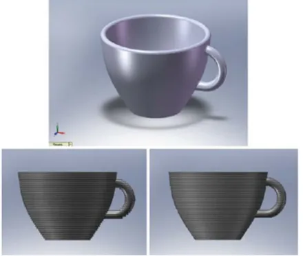
Obviously in the physical world, each layer must have a finite thickness to it and so the resulting part will be an approximation of the original data, as illustrated by Fig.1.1. The thinner each layer is, the closer the final part will be to the original. All commercialized AM machines to date use a layer-based approach, and the major ways that they differ are in the materials that can be used, how the layers are created, and how the layers are bonded to each other. Such differences will determine factors like the accuracy of the final part plus its material properties and mechanical properties. They will also determine factors like how quickly the part can be made, how much post-processing is required, the size of the AM machine used, and the overall cost of the machine and process.
This chapter will introduce the basic concepts of additive manufacturing and describe a generic AM process from design to application. It will go on to discuss the implications of AM on design and manufacturing and attempt to help in understanding how it has changed the entire product development process. Since AM is an increasingly important tool for product development, the chapter ends with a discussion of some related tools in the product development process.
1.2 What Are AM Parts Used for?
Throughout this book you will find a wide variety of applications for AM. You will also realize that the number of applications is increasing as the processes develop and improve. Initially, AM was used specifically to create visualization models for products as they were being developed. It is widely known that models can be much more helpful than drawings or renderings in fully understanding the intent of the designer when presenting the conceptual design. While drawings are quicker and easier to create, models are nearly always required in the end to fully validate the design.
Following this initial purpose of simple model making, AM technology has developed over time as materials, accuracy, and the overall quality of the output improved. Models were quickly employed to supply information about what is known as the “3 Fs” of Form, Fit, and Function. The initial models were used to help fully appreciate the shape and general purpose of a design (Form). Improved accuracy in the process meant that components were capable of being built to the tolerances required for assembly purposes (Fit). Improved material properties meant that parts could be properly handled so that they could be assessed according to how they would eventually work (Function).
Fig. 1.1 CAD image of a teacup with further images showing the effects of building using different layer thicknesses
1.2 What Are AM Parts Used for? 3
To say that AM technology is only useful for making models, though, would be inaccurate and undervaluing the technology. AM, when used in conjunction with other technologies to form process chains, can be used to significantly shorten product development times and costs. More recently, some of these technologies have been developed to the extent that the output is suitable for end use. This explains why the terminology has essentially evolved from rapid prototyping to additive manufacturing. Furthermore, use of high-power laser technology has meant that parts can now also be directly made in a variety of metals, thus extending the application range even further.
1.3 The Generic AM Process
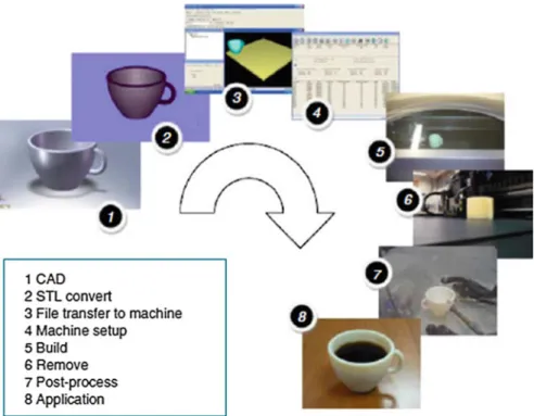
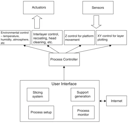
AM involves a number of steps that move from the virtual CAD description to the physical resultant part. Different products will involve AM in different ways and to different degrees. Small, relatively simple products may only make use of AM for visualization models, while larger, more complex products with greater engineering content may involve AM during numerous stages and iterations throughout the development process. Furthermore, early stages of the product development pro- cess may only require rough parts, with AM being used because of the speed at which they can be fabricated. At later stages of the process, parts may require careful cleaning and post-processing (including sanding, surface preparation, and painting) before they are used, with AM being useful here because of the complex- ity of form that can be created without having to consider tooling. Later on, we will investigate thoroughly the different stages of the AM process, but to summarize, most AM processes involve, to some degree at least, the following eight steps (as illustrated in Fig.1.2).
1.3.1 Step 1: CAD
All AM parts must start from a software model that fully describes the external geometry. This can involve the use of almost any professional CAD solid modeling software, but the output must be a 3D solid or surface representation. Reverse engineering equipment (e.g., laser and optical scanning) can also be used to create this representation.
1.3.2 Step 2: Conversion to STL
Nearly every AM machine accepts the STL file format, which has become a de facto standard, and nowadays nearly every CAD system can output such a file format. This file describes the external closed surfaces of the original CAD model and forms the basis for calculation of the slices.
1.3.3 Step 3: Transfer to AM Machine and STL File Manipulation
The STL file describing the part must be transferred to the AM machine. Here, there may be some general manipulation of the file so that it is the correct size, position, and orientation for building.
1.3.4 Step 4: Machine Setup
The AM machine must be properly set up prior to the build process. Such settings would relate to the build parameters like the material constraints, energy source, layer thickness, timings, etc.
1.3.5 Step 5: Build
Building the part is mainly an automated process and the machine can largely carry on without supervision. Only superficial monitoring of the machine needs to take place at this time to ensure no errors have taken place like running out of material, power or software glitches, etc.
Fig. 1.2 Generic process of CAD to part, showing all eight stages
1.3 The Generic AM Process 5
1.3.6 Step 6: Removal
Once the AM machine has completed the build, the parts must be removed. This may require interaction with the machine, which may have safety interlocks to ensure for example that the operating temperatures are sufficiently low or that there are no actively moving parts.
1.3.7 Step 7: Post-processing
Once removed from the machine, parts may require an amount of additional cleaning up before they are ready for use. Parts may be weak at this stage or they may have supporting features that must be removed. This therefore often requires time and careful, experienced manual manipulation.
1.3.8 Step 8: Application
Parts may now be ready to be used. However, they may also require additional treatment before they are acceptable for use. For example, they may require priming and painting to give an acceptable surface texture and finish. Treatments may be laborious and lengthy if the finishing requirements are very demanding.
They may also be required to be assembled together with other mechanical or electronic components to form a final model or product.
While the numerous stages in the AM process have now been discussed, it is important to realize that many AM machines require careful maintenance. Many AM machines use fragile laser or printer technology that must be carefully moni- tored and that should preferably not be used in a dirty or noisy environment. While machines are generally designed to operate unattended, it is important to include regular checks in the maintenance schedule, and that different technologies require different levels of maintenance. It is also important to note that AM processes fall outside of most materials and process standards; explaining the recent interest in the ASTM F42 Technical Committee on Additive Manufacturing Technologies, which is working to address and overcome this problem [1]. However, many machine vendors recommend and provide test patterns that can be used periodically to confirm that the machines are operating within acceptable limits.
In addition to the machinery, materials may also require careful handling. The raw materials used in some AM processes have limited shelf-life and may also be required to be kept in conditions that prevent them from unwanted chemical reactions. Exposure to moisture, excess light, and other contaminants should also be avoided. Most processes use materials that can be reused for more than one build. However, it may be that reuse could degrade the properties if performed many times over, and therefore a procedure for maintaining consistent material quality through recycling should also be observed.
1.4 Why Use the Term Additive Manufacturing?
By now, you should realize that the technology we are referring to is primarily the use of additive processes, combining materials layer by layer. The term additive manufacturing, or AM, seems to describe this quite well, but there are many other terms which are in use. This section discusses other terms that have been used to describe this technology as a way of explaining the overall purpose and benefits of the technology for product development.
1.4.1 Automated Fabrication (Autofab)
This term was popularized by Marshall Burns in his book of the same name, which was one of the first texts to cover this technology in the early 1990s [2]. The emphasis here is on the use of automation to manufacture products, thus implying the simplification or removal of manual tasks from the process. Computers and microcontrollers are used to control the actuators and to monitor the system variables. This term can also be used to describe other forms of Computer Numeri- cal Controlled (CNC) machining centers since there is no direct reference as to how parts are built or the number of stages it would take to build them, although Burns does primarily focus on the technologies also covered by this book. Some key technologies are however omitted since they arose after the book was written.
1.4.2 Freeform Fabrication or Solid Freeform Fabrication
The emphasis here is in the capability of the processes to fabricate complex geometric shapes. Sometimes the advantage of these technologies is described in terms of providing “complexity for free,” implying that it doesn’t particularly matter what the shape of the input object actually is. A simple cube or cylinder would take almost as much time and effort to fabricate within the machine as a complex anatomical structure with the same enclosing volume. The reference to
“Freeform” relates to the independence of form from the manufacturing process.
This is very different from most conventional manufacturing processes that become much more involved as the geometric complexity increases.
1.4.3 Additive Manufacturing or Layer-Based Manufacturing
These descriptions relate to the way the processes fabricate parts by adding material in layers. This is in contrast to machining technology that removes, or subtracts material from a block of raw material. It should be noted that some of the processes are not purely additive, in that they may add material at one point but also use subtractive processes at some stage as well. Currently, every commercial process works in a layer-wise fashion. However, there is nothing to suggest that this is an
1.4 Why Use the Term Additive Manufacturing? 7
essential approach to use and that future systems may add material in other ways and yet still come under a broad classification that is appropriate to this text. A slight variation on this, Additive Fabrication, is a term that was popularized by Terry Wohlers, a well-known industry consultant in this field and who compiles a widely regarded annual industry report on the state of this industry [3]. However, many professionals prefer the term “manufacturing” to “fabrication” since “fabri- cation” has some negative connotations that infer the part may still be a “prototype”
rather than a finished article. Additionally, in some regions of the world the term fabrication is associated with sheet metal bending and related processes, and thus professionals from these regions often object to the use of the word fabrication for this industry. Additive manufacturing is, therefore, starting to become widely used, and has also been adopted by Wohlers in his most recent publications and presentations.
1.4.4 Stereolithography or 3D Printing
These two terms were initially used to describe specific machines.
Stereolithography (SL) was termed by the US company 3D Systems [4, 5] and 3D Printing (3DP) was widely used by researchers at MIT [6] who invented an ink-jet printing-based technology. Both terms allude to the use of 2D processes (lithography and printing) and extending them into the third dimension. Since most people are very familiar with printing technology, the idea of printing a physical three-dimensional object should make sense. Many consider that eventually the term 3D Printing will become the most commonly used wording to describe AM technologies. Recent media interest in the technology has proven this to be true and the general public is much more likely to know the term 3D Printing than any other term mentioned in this book.
1.4.5 Rapid Prototyping
Rapid prototyping was termed because of the process this technology was designed to enhance or replace. Manufacturers and product developers used to find prototyping a complex, tedious, and expensive process that often impeded the developmental and creative phases during the introduction of a new product. RP was found to significantly speed up this process and thus the term was adopted.
However, users and developers of this technology now realize that AM technology can be used for much more than just prototyping.
Significant improvements in accuracy and material properties have seen this technology catapulted into testing, tooling, manufacturing, and other realms that are outside the “prototyping” definition. However, it can also be seen that most of the other terms described above are also flawed in some way. One possibility is that many will continue to use the term RP without specifically restricting it to the manufacture of prototypes, much in the way that IBM makes things other than
business machines and that 3M manufactures products outside of the mining industry. It will be interesting to watch how terminology develops in the future.
Where possible, we have used additive manufacturing or its abbreviation AM throughout this book as the generic term for the suite of technologies covered by this book. It should be noted that, in the literature, most of the terms introduced above are interchangeable; but different terminology may emphasize the approach used in a particular instance. Thus, both in this book and while searching for or reading other literature, the reader must consider the context to best understand what each of these terms means.
1.5 The Benefits of AM
Many people have described this technology as revolutionizing product develop- ment and manufacturing. Some have even gone on to say that manufacturing, as we know it today, may not exist if we follow AM to its ultimate conclusion and that we are experiencing a new industrial revolution. AM is now frequently referred to as one of a series of disruptive technologies that are changing the way we design products and set up new businesses. We might, therefore, like to ask “why is this the case?” What is it about AM that enthuses and inspires some to make these kinds of statements?
First, let’s consider the “rapid” character of this technology. The speed advan- tage is not just in terms of the time it takes to build parts. The speeding up of the whole product development process relies much on the fact that we are using computers throughout. Since 3D CAD is being used as the starting point and the transfer to AM is relatively seamless, there is much less concern over data conver- sion or interpretation of the design intent. Just as 3D CAD is becoming What You See Is What You Get (WYSIWYG), so it is the same with AM and we might just as easily say that What You See Is What You Build (WYSIWYB).
The seamlessness can also be seen in terms of the reduction in process steps.
Regardless of the complexity of parts to be built, building within an AM machine is generally performed in a single step. Most other manufacturing processes would require multiple and iterative stages to be carried out. As you include more features in a design, the number of these stages may increase dramatically. Even a relatively simple change in the design may result in a significant increase in the time required to build using conventional methods. AM can, therefore, be seen as a way to more effectively predict the amount of time to fabricate models, regardless of what changes may be implemented during this formative stage of the product development.
Similarly, the number of processes and resources required can be significantly reduced when using AM. If a skilled craftsman was requested to build a prototype according to a set of CAD drawings, he may find that he must manufacture the part in a number of stages. This may be because he must employ a variety of construc- tion methods, ranging from hand carving, through molding and forming techniques, to CNC machining. Hand carving and similar operations are tedious, difficult, and
1.5 The Benefits of AM 9
prone to error. Molding technology can be messy and obviously requires the building of one or more molds. CNC machining requires careful planning and a sequential approach that may also require construction of fixtures before the part itself can be made. All this of course presupposes that these technologies are within the repertoire of the craftsman and readily available.
AM can be used to remove or at least simplify many of these multistage processes. With the addition of some supporting technologies like silicone-rubber molding, drills, polishers, grinders, etc. it can be possible to manufacture a vast range of different parts with different characteristics. Workshops which adopt AM technology can be much cleaner, more streamlined, and more versatile than before.
1.6 Distinction Between AM and CNC Machining
As mentioned in the discussion on Automated Fabrication, AM shares some of its DNA with CNC machining technology. CNC is also a computer-based technology that is used to manufacture products. CNC differs mainly in that it is primarily a subtractive rather than additive process, requiring a block of material that must be at least as big as the part that is to be made. This section discusses a range of topics where comparisons between CNC machining and AM can be made. The purpose is not really to influence choice of one technology over another rather than to establish how they may be implemented for different stages in the product development process, or for different types of product.
1.6.1 Material
AM technology was originally developed around polymeric materials, waxes, and paper laminates. Subsequently, there has been introduction of composites, metals, and ceramics. CNC machining can be used for soft materials, like medium-density fiberboard (MDF), machinable foams, machinable waxes, and even some polymers.
However, use of CNC to shape softer materials is focused on preparing these parts for use in a multistage process like casting. When using CNC machining to make final products, it works particularly well for hard, relatively brittle materials like steels and other metal alloys to produce high accuracy parts with well-defined properties. Some AM parts, in contrast, may have voids or anisotropy that are a function of part orientation, process parameters or how the design was input to the machine, whereas CNC parts will normally be more homogeneous and predictable in quality.
1.6.2 Speed
High-speed CNC machining can generally remove material much faster than AM machines can add a similar volume of material. However, this is only part of the
picture, as AM technology can be used to produce a part in a single stage. CNC machines require considerable setup and process planning, particularly as parts become more complex in their geometry. Speed must therefore be considered in terms of the whole process rather than just the physical interaction of the part material. CNC is likely to be a multistage manufacturing process, requiring repositioning or relocation of parts within one machine or use of more than one machine. To make a part in an AM machine, it may only take a few hours; and in fact multiple parts are often batched together inside a single AM build. Finishing may take a few days if the requirement is for high quality. Using CNC machining, even 5-axis high-speed machining, this same process may take weeks with consid- erably more uncertainty over the completion time.
1.6.3 Complexity
As mentioned above, the higher the geometric complexity, the greater the advan- tage AM has over CNC. If CNC is being used to create a part directly in a single piece, then there may be some geometric features that cannot be fabricated. Since a machining tool must be carried in a spindle, there may be certain accessibility constraints or clashes preventing the tool from being located on the machining surface of a part. AM processes are not constrained in the same way and undercuts and internal features can be easily built without specific process planning. Certain parts cannot be fabricated by CNC unless they are broken up into components and reassembled at a later stage. Consider, for example, the possibility of machining a ship inside a bottle. How would you machine the ship while it is still inside the bottle? Most likely you would machine both elements separately and work out a way to combine them together as an assembly and/or joining process. With AM you can build the ship and the bottle all at once. An expert in machining must therefore analyze each part prior to it being built to ensure that it indeed can be built and to determine what methods need to be used. While it is still possible that some parts cannot be built with AM, the likelihood is much lower and there are generally ways in which this may be overcome without too much difficulty.
1.6.4 Accuracy
AM machines generally operate with a resolution of a few tens of microns. It is common for AM machines to also have different resolution along different orthog- onal axes. Typically, the vertical build axis corresponds to layer thickness and this would be of a lower resolution compared with the two axes in the build plane.
Accuracy in the build plane is determined by the positioning of the build mecha- nism, which will normally involve gearboxes and motors of some kind. This mechanism may also determine the minimum feature size as well. For example, SL uses a laser as part of the build mechanism that will normally be positioned using galvanometric mirror drives. The resolution of the galvanometers would
1.6 Distinction Between AM and CNC Machining 11
determine the overall dimensions of parts built, while the diameter of the laser beam would determine the minimum wall thickness. The accuracy of CNC machines on the other hand is mainly determined by a similar positioning resolution along all three orthogonal axes and by the diameter of the rotary cutting tools. There are factors that are defined by the tool geometry, like the radius of internal corners, but wall thickness can be thinner than the tool diameter since it is a subtractive process.
In both cases very fine detail will also be a function of the desired geometry and properties of the build material.
1.6.5 Geometry
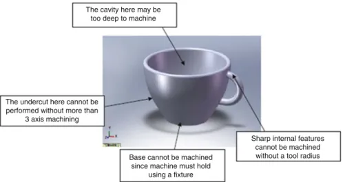
AM machines essentially break up a complex, 3D problem into a series of simple 2D cross-sections with a nominal thickness. In this way, the connection of surfaces in 3D is removed and continuity is determined by how close the proximity of one cross-section is with an adjacent one. Since this cannot be easily done in CNC, machining of surfaces must normally be generated in 3D space. With simple geometries, like cylinders, cuboids, cones, etc., this is a relatively easy process defined by joining points along a path; these points being quite far apart and the tool orientation being fixed. In cases of freeform surfaces, these points can become very close together with many changes in orientation. Such geometry can become extremely difficult to produce with CNC, even with 5-axis interpolated control or greater. Undercuts, enclosures, sharp internal corners, and other features can all fail if these features are beyond a certain limit. Consider, for example, the features represented in the part in Fig.1.3. Many of them would be very difficult to machine without manipulation of the part at various stages.
1.6.6 Programming
Determining the program sequence for a CNC machine can be very involved, including tool selection, machine speed settings, approach position and angle, etc.
Many AM machines also have options that must be selected, but the range, complexity, and implications surrounding their choice are minimal in comparison.
The worst that is likely to happen in most AM machines is that the part will not be built very well if the programming is not done properly. Incorrect programming of a CNC machine could result in severe damage to the machine and may even be a human safety risk.
1.7 Example AM Parts
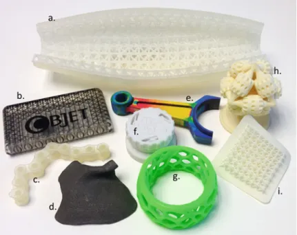
Figure1.4shows a montage of parts fabricated using some of the common AM processes. Part a. was fabricated using a stereolithography machine and depicts a simplified fuselage for an unmanned aerial vehicle where the skin is reinforced with
a conformal lattice structure (see Chap.4for more information about the process). A more complete description of this part is included in the Design for Additive Manufacturing chapter. Parts b. and c. were fabricated using material jetting (Chap. 7). Part b. demonstrates the capability of depositing multiple materials simultaneously, where one set of nozzles deposited the clear material, while another
The cavity here may be too deep to machine
The undercut here cannot be performed without more than
3 axis machining
Base cannot be machined since machine must hold
using a fixture
Sharp internal features cannot be machined without a tool radius
Fig. 1.3 Features that represent problems using CNC machining
Fig. 1.4 Montage of AM parts
1.7 Example AM Parts 13
set deposited the black material for the lines and the Objet name. Part c. is a section of chain. Both parts b. and c. have working revolute joints that were fabricated using clearances for the joints and dissolvable support structure. Part d. is a metal part that was fabricated in a metal powder bed fusion machine using an electron beam as its energy source (Chap. 5). The part is a model of a facial implant. Part e. was fabricated in an Mcor Technologies sheet lamination machine that has ink-jet printing capability for the multiple colors (Chap.9). Parts f. and g. were fabricated using material extrusion (Chap.6). Part f. is a ratchet mechanism that was fabricated in a single build in an industrial machine. Again, the working mechanism is achieved through proper joint designs and dissolvable support structure. Part g. was fabricated in a low-cost, personal machine (that one of the authors has at home). Parts h. and i. were fabricated using polymer powder bed fusion. Part h. is the well-known “brain gear” model of a three-dimensional gear train. When one gear is rotated, all other gears rotate as well. Since parts fabricated in polymer PBF do not need supports, working revolute and gear joints can be created by managing clearances and removing the loose powder from the joint regions. Part i. is another conformal lattice structure showing the shape complexity capability of AM technologies.
1.8 Other Related Technologies
The most common input method for AM technology is to accept a file converted into the STL file format originally built within a conventional 3D CAD system.
There are, however, other ways in which the STL files can be generated and other technologies that can be used in conjunction with AM technology. This section will describe a few of these.
1.8.1 Reverse Engineering Technology
More and more models are being built from data generated using reverse engineer- ing (RE) 3D imaging equipment and software. In this context, RE is the process of capturing geometric data from another object. These data are usually initially available in what is termed “point cloud” form, meaning an unconnected set of points representing the object surfaces. These points need to be connected together using RE software like Geomagic [7], which may also be used to combine point clouds from different scans and to perform other functions like hole-filling and smoothing. In many cases, the data will not be entirely complete. Samples may, for example, need to be placed in a holding fixture and thus the surfaces adjacent to this fixture may not be scanned. In addition, some surfaces may obscure others, like with deep crevices and internal features; so that the representation may not turn out exactly how the object is in reality. Recently there have been huge improvements in scanning technology. An adapted handphone using its inbuilt camera can now produce a high-quality 3D scan for just a few hundred dollars that even just a few
years ago would have required an expensive laser-scanning or stereoscopic camera system costing $100,000 or more.
Engineered objects would normally be scanned using laser-scanning or touch- probe technology. Objects that have complex internal features or anatomical models may make use of Computerized Tomography (CT), which was initially developed for medical imaging but is also available for scanning industrially produced objects. This technique essentially works in a similar way to AM, by scanning layer by layer and using software to join these layers and identify the surface boundaries. Boundaries from adjacent layers are then connected together to form surfaces. The advantage of CT technology is that internal features can also be generated. High-energy X-rays are used in industrial technology to create high- resolution images of around 1μm. Another approach that can help digitize objects is the Capture Geometry Inside [8] technology that also works very much like a reverse of AM technology, where 2D imaging is used to capture cross-sections of a part as it is machined away layer by layer. Obviously this is a destructive approach to geometry capture so it cannot be used for every type of product.
AM can be used to reproduce the articles that were scanned, which essentially would form a kind of 3D facsimile (3D Fax) process. More likely, however, the data will be modified and/or combined with other data to form complex, freeform artifacts that are taking advantage of the “complexity for free” feature of the technology. An example may be where individual patient data are combined with an engineering design to form a customized medical implant. This is something that will be discussed in much more detail later on in this book.
1.8.2 Computer-Aided Engineering
3D CAD is an extremely valuable resource for product design and development.
One major benefit to using software-based design is the ability to implement change easily and cheaply. If we are able to keep the design primarily in a software format for a larger proportion of the product development cycle, we can ensure that any design changes are performed virtually on the software description rather than physically on the product itself. The more we know about how the product is going to perform before it is built, the more effective that product is going to be. This is also the most cost-effective way to deal with product development. If problems are only noticed after parts are physically manufactured, this can be very costly. 3D CAD can make use of AM to help visualize and perform basic tests on candidate designs prior to full-scale commitment to manufacturing. However, the more complex and performance-related the design, the less likely we are to gain sufficient insight using these methods. However, 3D CAD is also commonly linked to other software packages, often using techniques like finite element method (FEM) to calculate the mechanical properties of a design, collectively known as Computer-Aided Engineering (CAE) software. Forces, dynamics, stresses, flow, and other properties can be calculated to determine how well a design will perform under certain conditions. While such software cannot easily predict the exact
1.8 Other Related Technologies 15
behavior of a part, for analysis of critical parts a combination of CAE, backed up with AM-based experimental analysis, may be a useful solution. Further, with the advent of Direct Digital Manufacture, where AM can be used to directly produce final products, there is an increasing need for CAE tools to evaluate how these parts would perform prior to AM so that we can build these products right first time as a form of Design for Additive Manufacturing (D for AM).
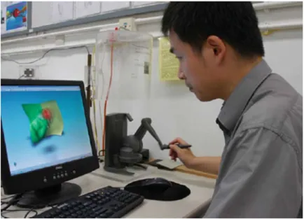
1.8.3 Haptic-Based CAD
3D CAD systems are generally built on the principle that models are constructed from basic geometric shapes that are then combined in different ways to make more complex forms. This works very well for the engineered products we are familiar with, but may not be so effective for more unusual designs. Many consumer products are developed from ideas generated by artists and designers rather than engineers. We also note that AM has provided a mechanism for greater freedom of expression. AM is in fact now becoming a popular tool for artists and sculptors, like, for example, Bathsheba Grossman [9] who takes advantage of the geometric freedom to create visually exciting sculptures. One problem we face today is that some computer-based design tools constrain or restrict the creative processes and that there is scope for a CAD system that provides greater freedom. Haptic-based CAD modeling systems like the experimental system shown in Fig.1.5[10], work in a similar way to the commercially available Freeform [11] modeling system to provide a design environment that is more intuitive than other standard CAD systems. They often use a robotic haptic feedback device called the Phantom to
Fig. 1.5 Freeform modeling system
provide force feedback relating to the virtual modeling environment. An object can be seen on-screen, but also felt in 3D space using the Phantom. The modeling environment includes what is known as Virtual Clay that deforms under force applied using the haptic cursor. This provides a mechanism for direct interaction with the mod